
Verwandte Anleitungen für Stahl 8013/3 Serie


Inhaltszusammenfassung für Stahl 8013/3 Serie
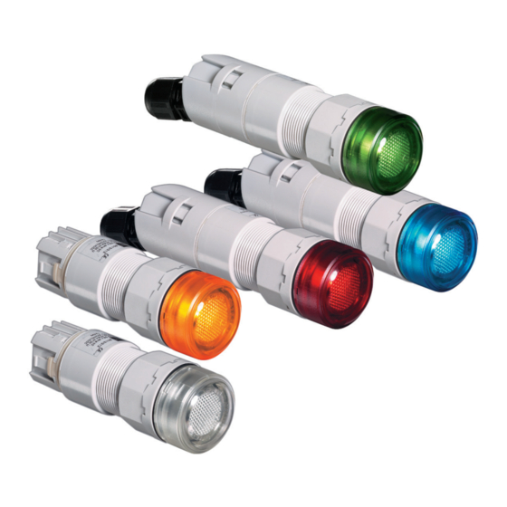
- Seite 1 Betriebsanleitung Additional languages r-stahl.com LED-Leuchtmelder für Schalttafeleinbau Reihe 8013/3...
-
Seite 2: Inhaltsverzeichnis
Inhaltsverzeichnis Inhaltsverzeichnis Allgemeine Angaben....................3 Hersteller......................3 Zu dieser Betriebsanleitung .................3 Weitere Dokumente .....................3 Konformität zu Normen und Bestimmungen ............3 Erläuterung der Symbole ..................4 Symbole in der Betriebsanleitung ................4 Symbole am Gerät ....................4 Sicherheit ......................5 Bestimmungsgemäße Verwendung..............5 Qualifikation des Personals .................5 Restrisiken ......................6 Transport und Lagerung ..................7 Montage und Installation..................8 Montage / Demontage ..................8... -
Seite 3: Allgemeine Angaben
▶ Betriebsanleitung dem Bedien- und Wartungspersonal jederzeit zugänglich machen. ▶ Betriebsanleitung an jeden folgenden Besitzer oder Benutzer des Geräts weitergeben. ▶ Betriebsanleitung bei jeder von R. STAHL erhaltenen Ergänzung aktualisieren. ID-Nr.: 129221 / 8013603300 Publikationsnummer: 2022-06-28·BA00·III·de·04 Die Originalbetriebsanleitung ist die englische Ausgabe. -
Seite 4: Erläuterung Der Symbole
Erläuterung der Symbole Erläuterung der Symbole Symbole in der Betriebsanleitung Symbol Bedeutung Hinweis zum leichteren Arbeiten Gefahrensituation, die bei Nichtbeachtung der GEFAHR! Sicherheitsmaßnahmen zum Tod oder zu schweren Verletzungen mit bleibenden Schäden führen kann. Gefahrensituation, die bei Nichtbeachtung der WARNUNG! Sicherheitsmaßnahmen zu schweren Verletzungen führen kann. -
Seite 5: Sicherheit
Normen und Bestimmungen umfasst. Für Tätigkeiten in explosionsgefährdeten Bereichen sind weitere Kenntnisse erforderlich! R. STAHL empfiehlt einen Kenntnisstand, der in folgenden Normen beschrieben wird: • IEC/EN 60079-14 (Projektierung, Auswahl und Errichtung elektrischer Anlagen) • IEC/EN 60079-17 (Prüfung und Instandhaltung elektrischer Anlagen) •... -
Seite 6: Restrisiken
Gerät nur in Originalverpackung oder gleichwertiger Verpackung transportieren. ▶ Verpackung und Gerät auf Beschädigung prüfen. Beschädigungen umgehend an R. STAHL melden. Beschädigtes Gerät nicht in Betrieb nehmen. ▶ Gerät in Originalverpackung, trocken (keine Betauung), in stabiler Lage und sicher vor Erschütterungen lagern. -
Seite 7: Verletzungsgefahr
Transport und Lagerung 3.3.2 Verletzungsgefahr Stromschlag Während des Betriebs und der Instandhaltung liegen zeitweise hohe Spannungen am Gerät an, daher muss während der Installation das Gerät spannungsfrei geschaltet sein. Durch Kontakt mit Leitungen, die Spannung führen, können Personen schwere Stromschläge und damit Verletzungen erleiden. ▶... -
Seite 8: Montage Und Installation
Montage und Installation Montage und Installation Montage / Demontage ▶ Gerät sorgfältig und unter Beachtung der Sicherheitshinweise (siehe Kapitel "Sicherheit") sowie der Projektierungsvorgaben montieren. ▶ Folgende Einbaubedingungen und Montageanweisungen genau durchlesen und exakt befolgen. 5.1.1 Gebrauchslage Die Gebrauchslage ist beliebig. 5.1.2 Einbaubedingungen Für den Netzanschluss haben die Leuchtmelder Typ 8013/3.1 und 8013/3.2 schraubenlose Klemmen. -
Seite 9: Einbau Der Geräte 8013/3.2 In Die Schalttafel
Montage und Installation Einbau der Geräte 8013/3.2 in die Schalttafel ▶ Überwurfmutter so weit wie möglich gegen den Uhrzeigersinn drehen. ▶ Betätiger von der Vorderseite durch die Öffnung der Schalttafel schieben und darauf achten, dass die Dichtung bündig an der Schalttafel anliegt, in dieser Position verriegeln. ▶... -
Seite 10: Einbau Der Geräte 8013/3.1 In Die Schalttafel
Montage und Installation Einbau der Geräte 8013/3.1 in die Schalttafel Anschlussraum öffnen ▶ 11618T00 Schraubendreher (mit Schlitz – 0,6 x 3,5 mm) an einer der Verriegelungslaschen ansetzen. ▶ Um 90° drehen. ▶ Kappe etwas zurückziehen und in dieser Position halten. ▶... - Seite 11 Montage und Installation Leiteranschluss zu den Federzugklemmen 11614T00 ▶ Ausschnitt mit Federzugklemmen (1) (Anschlussquerschnitt siehe Kapitel "Technische Daten"). ▶ Federzugklemme mit einem Schraubendreher (mit Schlitz – 0,6 x 3,5 mm) durch Einführen in die viereckige Aussparung öffnen und die Klemme offen halten (2). ▶...
-
Seite 12: Wechsel Der Farbigen Vorsatzkappen
Inbetriebnahme Wechsel der farbigen Vorsatzkappen ▶ 11354E00 Schraubendreher an die Aussparung ansetzen und drehen. ▶ Vorsatzkappe von Leuchtvorsatz abziehen. ▶ Neue Vorsatzkappe aufsetzen und einrasten. Inbetriebnahme Vor Inbetriebnahme folgende Prüfschritte durchführen: ▶ Gerät auf Schäden prüfen. ▶ Montage und Installation auf korrekte Durchführung prüfen. ▶... -
Seite 13: Wartung
▶ Rücksendung bzw. Verpackung der Geräte nur in Absprache mit R. STAHL durchführen! Dazu mit der zuständigen Vertretung von R. STAHL Kontakt aufnehmen. Für die Rücksendung im Reparatur- bzw. Servicefall steht der Kundenservice von R. STAHL zur Verfügung. ▶ Kundenservice persönlich kontaktieren. -
Seite 14: Entsorgung
Umweltgerechte Entsorgung aller Bauteile gemäß den gesetzlichen Bestimmungen sicherstellen. Zubehör und Ersatzteile HINWEIS! Fehlfunktion oder Geräteschaden durch den Einsatz nicht originaler Bauteile. Nichtbeachten kann zu Sachschäden führen. ▶ Nur Original-Zubehör und Original-Ersatzteile der R. STAHL Schaltgeräte GmbH (siehe Datenblatt) verwenden. LED-Leuchtmelder 129221 / 8013603300 für Schalttafeleinbau 2022-06-28·BA00·III·de·04... -
Seite 15: 13.1 Technische Daten
Anhang A Anhang A 13.1 Technische Daten Explosionsschutz Global (IECEx) Gas und Staub 8013/3.1 IECEx PTB 07.0010X 8013/3.2 IECEx PTB 07.0012U 8013/3.3 IECEx PTB 07.0010X Ex e 8013/311 Ex db eb mb IIC T6 Gb 8013/312 Ex db eb mb IIC Gb 8013/313 Ex db eb mb IIC T6 Gb Ex i... - Seite 16 Montage / Installation Leitungseinführung 8013/3.1 M16 x 1,5 (Ø 2 ... 9 mm) 8013/3.3 Anschlussart Leitungsquerschnitt 8013/3.1 + /3.2 0,75 ... 1,5 mm 8013/3.3 2 x 0,75 mm Weitere technische Daten, siehe r-stahl.com. LED-Leuchtmelder 129221 / 8013603300 für Schalttafeleinbau 2022-06-28·BA00·III·de·04 Reihe 8013/3...
-
Seite 17: 14.1 Maßangaben / Befestigungsmaße
Anhang B Anhang B 14.1 Maßangaben / Befestigungsmaße Maßzeichnungen (alle Maße in mm [Zoll]) – Änderungen vorbehalten Ø [ 1,50] Ø Ø [ 1,50] Ø 38,50 Ø [ 1,52] Ø 38,50 Ø [ 1,52] Ø 42 [ 1, 65] 36,50 Ø... - Seite 19 Operating instructions Additional languages r-stahl.com LED indicator lamps for panel mounting Series 8013/3...
- Seite 20 Contents Contents General Information .....................3 Manufacturer......................3 About these Operating Instructions..............3 Further Documents ....................3 Conformity with Standards and Regulations............3 Explanation of Symbols ..................4 Symbols used in these Operating Instructions.............4 Symbols on the Device ..................4 Safety........................5 Intended Use......................5 Personnel Qualification ..................5 Residual Risks .....................6 Transport and Storage ..................7 Mounting and Installation ..................8 Mounting/Dismounting ..................8...
-
Seite 21: General Information
Make the operating instructions accessible to operating and maintenance staff at all times. ▶ Pass the operating instructions on to each subsequent owner or user of the device. ▶ Update the operating instructions every time R. STAHL issues an amendment. ID no.: 129221 / 8013603300 Publication code: 2022-06-28·BA00·III·en·04... -
Seite 22: Explanation Of Symbols
Explanation of Symbols Explanation of Symbols Symbols used in these Operating Instructions Symbol Meaning Handy hint for making work easier Dangerous situation which can result in fatal or severe injuries DANGER! causing permanent damage if the safety measures are not complied with. -
Seite 23: Safety
Specialists who perform these activities must have a level of knowledge that meets applicable national standards and regulations. Additional knowledge is required for any activity in hazardous areas! R. STAHL recommends having a level of knowledge equal to that described in the following standards: •... -
Seite 24: Residual Risks
▶ Transport the device only in its original packaging or in equivalent packaging. ▶ Check the packaging and the device for damage. Report any damage to R. STAHL immediately. Do not commission a damaged device. ▶ Store the device in its original packaging in a dry place (with no condensation), and make sure that it is stable and protected against the effects of vibrations and knocks. -
Seite 25: Risk Of Injury
Transport and Storage 3.3.2 Risk of Injury Electric shock During operation and maintenance, the device has high voltage applied to it at times. Because of this, the device must be de-energised during installation. Persons coming into contact with electrical lines carrying voltage can suffer severe electric shocks and, consequently, injuries. -
Seite 26: Mounting And Installation
Mounting and Installation Mounting and Installation Mounting/Dismounting ▶ Mount the device carefully and only in accordance with the safety notes (see "Safety" chapter) and the project engineering specifications. ▶ Read through the following installation conditions and assembly instructions carefully and follow them precisely. -
Seite 27: Installation Of Devices 8013/3.2 Into The Panel
Mounting and Installation Installation of Devices 8013/3.2 into the Panel ▶ Turn the union nut counter-clockwise as far as it will go. ▶ Push the actuator from the front through the panel opening, making sure the seal is seated flat against the panel, and lock it in position. ▶... -
Seite 28: Installation Of Devices 8013/3.1 Into The Panel
Mounting and Installation Installation of Devices 8013/3.1 into the Panel Opening the connection chamber ▶ 11618T00 Position the screwdriver (blade – 0.6 x 3.5 mm) against one of the locking tabs. ▶ Turn it 90°. ▶ Pull the cap back a little and hold it in this position. ▶... - Seite 29 Mounting and Installation Conductor connection to spring clamp terminals 11614T00 ▶ Section with spring clamp terminals (1) (for connection cross-section, see the "Technical data" chapter). ▶ Open the spring clamp terminal with a screwdriver (blade – 0.6 x 3.5 mm) by inserting it into the square cut-out and hold the terminal open (2).
-
Seite 30: Changing The Colours Of The Actuator Caps
Commissioning Changing the Colours of the Actuator Caps ▶ 11354E00 Insert a screwdriver into the cut-out and turn it. ▶ Pull the lamp actuator cap out. ▶ Position the new actuator cap and snap it into place. Commissioning Before commissioning, carry out the following checks: ▶... -
Seite 31: Overhaul
Returning the Device ▶ Only return or package the devices after consulting R. STAHL! Contact the responsible representative from R. STAHL. R. STAHL's customer service is available to handle returns if repair or service is required. ▶ Contact customer service personally. ▶... -
Seite 32: Disposal
NOTICE! Malfunction or damage to the device due to the use of non-original components. Non-compliance can result in material damage. ▶ Use only original accessories and spare parts from R. STAHL Schaltgeräte GmbH (see data sheet). LED indicator lamps 129221 / 8013603300 for panel mounting 2022-06-28·BA00·III·en·04... -
Seite 33: Appendix A
Appendix A Appendix A 13.1 Technical Data Explosion protection Global (IECEx) Gas and dust 8013/3.1 IECEx PTB 07.0010X 8013/3.2 IECEx PTB 07.0012U 8013/3.3 IECEx PTB 07.0010X Ex e 8013/311 Ex db eb mb IIC T6 Gb 8013/312 Ex db eb mb IIC Gb 8013/313 Ex db eb mb IIC T6 Gb Ex i... - Seite 34 M16 x 1.5 (dia. 2 to 9 mm) 8013/3.3 Connection type Conductor cross-section 8013/3.1 + /3.2 0.75 to 1.5 mm 8013/3.3 2 x 0.75 mm For further technical data, see r-stahl.com. LED indicator lamps 129221 / 8013603300 for panel mounting 2022-06-28·BA00·III·en·04 Series 8013/3...
-
Seite 35: Appendix B
Appendix B Appendix B 14.1 Dimensions/Fastening Dimensions Dimensional drawings (all dimensions in mm [inch]) – Subject to change Ø [ 1,50] Ø Ø [ 1,50] Ø 38,50 Ø [ 1,52] Ø 38,50 Ø [ 1,52] Ø 42 [ 1, 65] 36,50 Ø...