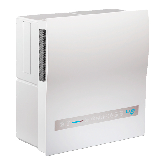
Lunos Nexxt Einbauanleitung
Dezentrales lüftungssystem mit wärmerückgewinnung
Vorschau ausblenden
Andere Handbücher für Nexxt:
- Einbauanleitung und bedienungsanleitung (54 Seiten) ,
- Einbauanleitung (16 Seiten) ,
- Bedienungsanleitung (9 Seiten)
Inhaltsverzeichnis
Werbung
Verfügbare Sprachen
Verfügbare Sprachen
Quicklinks
Werbung
Inhaltsverzeichnis

Inhaltszusammenfassung für Lunos Nexxt
- Seite 1 Einbauanleitung Dezentrales Lüftungssystem mit Wärmerückgewinnung Typ Ne Einbaugehäuse - Bitte an den Nutzer weiterleiten - Installation Manual Decentralised Ventilation System with Heat Recovery Type Ne Wall housing - Please pass on to user - Vertrieb Schweiz durch...
- Seite 2 t - Aufputz 167* t - Unterputz 167*...
- Seite 3 480 ** 15 cm 30 cm...
- Seite 5 (N) (O) (P) (Q)
- Seite 6 Ø162 mm Ø 8 mm (IW)
- Seite 7 Ø 162 mm...
- Seite 8 (Z1) (Z2) (Z3) (Z4) (Z6) (Z5)
- Seite 9 Silvento ec Silvento ec Silvento ec (Z7) (Z8)
-
Seite 10: Inhaltsverzeichnis
Einbauanleitung Inhalt Seite: Zu dieser Anleitung, Sicherheitshinweise, Technische Daten, Einsatzbereich, Entsorgen Maßbilder Wandgehäuse Ne Einbauposition, Montagebesonderheiten, Einbaubeispiele, Versandeinheiten Montage - Klappenverschluß Montage - Aufputzmontage Montage - Unterputzmontage Montage - Montage Außenblenden Elektrischer Anschluss - Anschlussbilder Zu dieser Anleitung • Diese Anleitung beschreibt die Aufputzmontage und Unterputzmontage der dezentralen Lüftungs- geräte mit Wärmerückgewinnung Typ Ne •... -
Seite 11: Maßbilder
Maßbilder (Bilder 1 und 2) Bild 1: Ne t - Aufputz Bild 2: Ne t - Unterputz (A) Adapter bzw. elektrischer Klappenverschluss * in Bezug auf Blende (alle Maße in mm) Wandgehäuse Ne t (Bild 3) Bild 3: ** Aussparung Wand min. 482 mm; *** Tiefe Ausschnitt min. 172 mm (B) Netzanschluss Aufputz (alle Maße in mm) Achtung! Der umlaufende Kragen muss im fertigestellten Unterputzeinbau mit seiner Oberkante... -
Seite 12: Montage - Klappenverschluß
Bild 12: EPP-Adapter Typ 2/AD 160 Bestell-Nr.: 39965 Außenverschlüsse (wahlweise): Bild 13: Außenblende Typ 1/EGA Bestell-Nr.: 40019 (H) Deckel; (I) Außenblende-Unterteil + Schraubenzubehör Bild 14: Wetterschutzhaube Typen: 1/HWE-2 weiß Bestell-Nr.: 40107 1/HAZ-2 anthrazit Bestell-Nr.: 40108 (J) Abdeckung; (K) Rahmen; (L) Verbindungsschrauben + Schraubenzubehör Montage - Klappenverschluß... -
Seite 13: Montage - Unterputzmontage
Montage - Unterputzmontage (Bilder 23 bis 27) Bild 23: Legen Sie mit Hilfe des Einbaugehäuses die Position der Kernbohrung für das Wanddurch- führungsrohr fest. Stellen Sie die Kernbohrung für das Wanddurchführungsrohr her. Bild 24: Montieren Sie das Wanddurchführungsrohr innen wandbündig zur Wandöffnung, außen mit leichtem Überstand zur Überbrückung der Außenputzdicke. - Seite 14 Bild 29: Manuelles Schalten der Volumenstromstufen über einen externen zweipoligen Taster: L1 = Volumenstromstufe größer; L2 = Volumenstromstufe kleiner Hinweis: DIP-Schalter 2 muss hierfür in Position OFF sein. ((Z5) Brücke; (Z6) 2-Wippentaster zweipolig) Bild 30: Manuelles Schalten der Volumenstromstufen über einen externen einpoligen Taster an L1 und gleichzeitigem Betrieb von einem oder mehreren Abluftventilatoren über Kopplung an L2 zum Ausgleich des durch die Abluftventilatoren entstehenden zusätzlichen Unterdrucks.
-
Seite 15: About This Manual, Safety Instructions, Technical Data, Range Of Application, Disposal
Installation Manual Contents Page: About this manual, Safety instructions, Technical data, Range of application, Disposal Dimension drawings Wall housing Ne Installation position, Special mounting features Installation examples, Shipping units Installation - Flap closure Installation - Surface mounting Installation - Flush mounting Installation - Outer screens Electrical connection - Connection diagrams About this manual... -
Seite 16: Dimension Drawings
Dimension drawings (Figures 1 and 2) Figure 1: Ne t - surface mounting Figure 2: Ne t - flush mounting A) Adapter or electrical flap closure * in terms of screen (All dimensions in mm) Wall housing Ne t (Figure 3) Figure 3: ** recess wall min. -
Seite 17: Installation - Flap Closure
Figure 12: EPP adapter type 2/AD 160 Order No.: 39965 External closures (optional): Figure 13: Outer screen type 1/EGA Order No.: 40019 (H) cover; (I) lower part of outer screen + screw accessories Figure 14: Weather protection hood types: 1/HWE-2 white Order No.: 40107 1/HAZ-2 anthracite Order No.: 40108 (J) cover;... -
Seite 18: Installation - Outer Screens
Installation - Flush mounting (Figures 23 and 27) Figure 23: Use the installation housing to determine the position of the core drill hole for the wall duct. Make the core bore for the wall duct. Figure 24: Mount the wall duct on the inside flush with the wall to the wall opening, on the outside with a slight projection to bridge the exterior plaster thickness. - Seite 19 Figure 29: Manual switching of the volume flow stages via an external two-pole push-button: L1 = volume flow stage higher; L2 = volume flow stage lower Note: For this purpose, DIP switch 2 must be in the OFF position. ((Z5) bridge; (Z6) double-pole 2 rocker switch) Figure 30: Manual switching of the volume flow stages via an external single-pole push-button at L1 and simultaneous operation of one or more exhaust air fans via coupling at L2 to com- pensate for the additional negative pressure created by the exhaust air fans.
- Seite 20 Notes Vertrieb Schweiz durch WESCO AG Schul-, Büro- und Wohnungslüftung Tägerhardstrasse 110 Tel. +41 (0)56 438 12 12 CH-5430 Wettingen balance@wesco.ch...


