Lunos Silvento Einbauanleitung
Vorschau ausblenden
Andere Handbücher für Silvento:
- Einbauanleitung (9 Seiten) ,
- Demontageanleitung (5 Seiten) ,
- Einbauanleitung (36 Seiten)

Verwandte Anleitungen für Lunos Silvento


Inhaltszusammenfassung für Lunos Silvento
- Seite 1 Einbauanleitung Silvento Unterputz-Gehäuse 1 und 2-Raum - Bitte an den Nutzer weiterleiten - Installation Manual Silvento Flush-Mounted Housing 1 and 2-Room - Please pass on to user -...
-
Seite 2: Inhaltsverzeichnis
Hinweise Hints Abmessungen Dimensions Einbaubeispiele Installation examples Liefereinheiten Delivery units Montage Assembly Elektrischer Anschluss Elektrical connection Filterwechsel Filter replacement Textteil / Beschreibung Text part / description... - Seite 3 2,25 m ...
- Seite 4 45 mm 3/S2 44 mm 323 mm 90,5 mm 12 mm 91 mm 52 mm 3/UP (R) 040125 260 mm 69 mm 44 mm 3/S2 323 mm 12 mm 90,5 mm 91 mm 52 mm 3/UP (A) 040125 260 mm...
- Seite 5 53 mm 68,5 mm 49,5 mm 102,5 mm 12 mm 3/UP-BR 039160 260 mm 69 mm 73 mm 102,5 mm 12 mm 3/UP-BA 039179 260 mm...
- Seite 6 68,5 mm 53 mm 49,5 mm 102,5 mm 12 mm 64 mm 3/UP-2BR 039187 260 mm 73 mm 69 mm 64 mm 102,5 mm 12 mm 3/UP-2BA 039195 260 mm...
- Seite 7 3/UP-BR 3/UP (R) 1/WE 115 3/S2 3/UP (A) 3/UP (R) DN80 DN80 3/UP (R) 8/BS...
- Seite 8 040125 3/UP 039160 039179 3/UP-BR 3/UP-BA 039187 039195 3/UP-2BR 3/UP-2BA...
- Seite 9 040078 V-EC 039209 039543 3/S2 8/B2 □ 136 mm □ 136 mm 8/BS DN 80...
- Seite 10 ...
- Seite 11 5.10 5.11 5.12 12 mm 40 mm 6 mm...
- Seite 12 5.13 5.14 5.15...
- Seite 13 5.16 3/UP 5.17 5.18 „UP“ 5.20 5.19 DN80 2/ZSKA 8/BS...
- Seite 14 5/W2...
-
Seite 15: Zu Dieser Anleitung, Sicherheitshinweise, Einsatzbereich, Entsorgen
Einbauanleitung Inhalt: Seite: Zu dieser Anleitung, Sicherheitshinweise, Einsatzbereich, Entsorgen Technische Daten, Hinweise Einbaubeispiele, Versandeinheiten Montage - Winkel und Umlenkung montieren Montage - Gehäuse und elektrischer Anschluss Montage - Ventilatoreinsatz und Designblende Montage - Zweitraumanschluss Elektrischer Anschluss Filterwechsel, Reinigung, Zusatz- und Austauschteile Zu dieser Anleitung ... -
Seite 16: Technische Daten, Hinweise
(bei aktiver Feuchteregelung „quasi“-stufenlos zwischen 15 und 60/90* m³/h) * je nach Steuerplatine Jeder Silvento ec kann mit einer Steuerplatine ohne Feuchtesensor oder mit Feuchtesensor kombi- niert werden, jede Steuerplatine ist mit jeweils einem Erweiterungsmodul kombinierbar. Daraus ergeben sich folgende Konfigurationsmöglichkeiten:... -
Seite 17: Hinweise
(„Ausblas nach hinten“) Ausblasöffnung möglich, die nach Zweckmäßigkeit wählbar ist. Bei Brandschutz muss die Schachtwand die geforderte Feuerwiderstandsdauer besitzen! 4 Versandeinheiten Überprüfen Sie die Lieferung auf Vollständigkeit und einwandfreien Zustand! Alle Wandeinbaugehäuse inklusive: Ventilatoreinsatz Silvento V-EC inklusive: Rückschlagklappe Filterrahmen mit Filter ... -
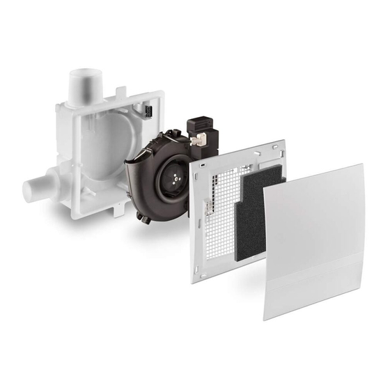
Seite 18: Montage - Ventilatoreinsatz Und Designblende
Im Kunststoffgehäuse 5. 5 Stutzen mit Rückschlagklappe durch Verdrehen ausrasten, in Korrekturlage wieder einrasten Im Brandschutzgehäuse Einsatz mit Rückschlagklappe abschrauben, verdrehen, wieder anschrauben ((F) 5.7). Nach erfolgter Korrektur, die Schalldämmung wieder einsetzen! Montagebügel mit beiliegenden Schraubenzubehör am Gehäuse montieren. Befestigen Sie das Gehäuse mit Hilfe der Montagebügel an der Schachtwand. (Schraubenzubehör nicht mitgeliefert) 5.10 Flexrohr anschließen und Verbindung von Flexrohr mit Hauptleitung und Stutzen mit Dicht-... -
Seite 19: Montage - Zweitraumanschluss
Zusätzliche Installationen und elektrische Bauelemente im Lüftungsgerät sind unzulässig! Anschlussbilder für weitere Lüfterfunktionen auf Anfrage! Hinweis: Eine Vielzahl von Lüftungsfunktionen des Silvento ec lassen sich über die in der Steuerplatine dieses Typs integrierten DIP-Schalter und über mögliche Zusatzmodule realisieren. Entnehmen Sie bitte diese Informationen der „Einbauanleitung E186 Ventilatoreinsatz Silvento ec“. -
Seite 20: Filterwechsel
Je nach Steuerplatine, DIP-Schalterstellung und Modul: Mit Zeitnachlauf (Basisplatine): Deaktivieren der Nachlauffunktionen (L2), Dauerbetrieb Grundlüftung oder AUS entsprechend DIP-Schalter 1 und 2 schaltbar auf Bedarfslüftung (L1) entsprechend DIP-Schalter 6 und 7. Mit Feuchteregelung (Komfortplatine): Deaktivierbare Feuchteregelung (L2), schaltbar auf Bedarfslüftung (L1) Hinweis: Keine Lichtkopplung bei VDE-konformer Installation möglich ((R) Brücke) Je nach Steuerplatine, DIP-Schalterstellung und Modul:... - Seite 27 Notes...
- Seite 28 Notes LUNOS Germany LUNOS Lüftungstechnik GmbH Phone +49 30 362 001-0 für Raumluftsysteme +49 30 362 001-89 Wilhelmstr. 31 info@lunos.de 13593 Berlin ∙ Germany www.lunos.de...