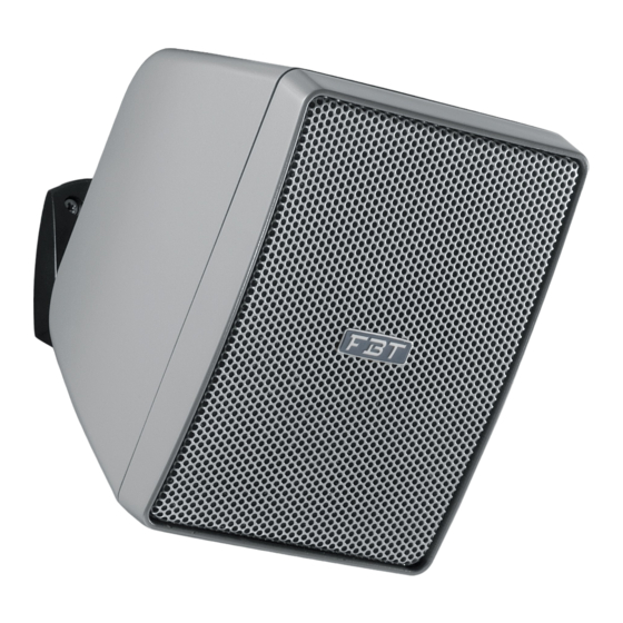
Inhaltszusammenfassung für Fbt SHADOW 105T
- Seite 1 FBT elettronica SpA Via Paolo Soprani 1 - Zona Ind.le Squartabue - 62019 RECANATI - ITALY CODE 37938 # 27/04/2022 - rev 02 Tel. 071 750591 - Fax. 071 7505920 - email: info@fbt.it - www.fbt.it...
-
Seite 3: Inhaltsverzeichnis
AVVERTENZE CARATTERISTICHE TECNICHE INSTALLAZIONE 3 - 4 DIMENSIONI COLLEGAMENTI 6 - 7 WARNING TECHNICAL FEATURES INSTALLATION 10 - 11 DIMENSIONS CONNECTIONS 13 - 14 ATTENTION CARACTÉRISTIQUES TECHNIQUES INSTALLATION 17 - 18 DIMENSIONS CONNEXIONS 20 - 21 VORSICHT TECHNISCHE DATEN INSTALLATION 24 - 25 ABMESSUNGEN ANSCHLÜSSE... -
Seite 5: Caratteristiche Tecniche
CARATTERISTICHE TECNICHE... -
Seite 6: Installazione
INSTALLAZIONE... - Seite 7 INSTALLAZIONE N.B. Per ottenere il grado di protezione IP55 è necessario che l'angolo di rotazione del diffusore sia minimo di 15° verso il basso (fig.1). fig. 1 Togliere il supporto a parete dal diffusore per mezzo dell'inserto filettato (B) Inserire il cavo di alimentazione nel foro (C). Fissare anche il cavetto di protezione (D).
-
Seite 8: Dimensioni
DIMENSIONI 200 mm 168 mm... -
Seite 9: Collegamenti
COLLEGAMENTI SISTEMI A TENSIONE COSTANTE SISTEMI A IMPEDENZA COSTANTE... - Seite 10 COLLEGAMENTI LINEA A TENSIONE COSTANTE • Collegare il conduttore NERO (com) del diffusore alla linea 100V che fa capo al morsetto dell'amplificatore contrassegnato con "-" / "0" / "com". • Scegliere un conduttore tra quelli contraddistinti dai colori GIALLO / VERDE / BLU / MARRONE, in base alla potenza desiderata e collegarlo alla linea 100V che fa capo al morsetto dell'amplificatore contrassegnato con "100V"...
-
Seite 12: Warning
WARNING... -
Seite 13: Technical Specifications
TECHNICAL SPECIFICATIONS... -
Seite 14: Installation
INSTALLATION... - Seite 15 INSTALLATION N.B. To obtain the IP55 protective degree, the rotation angle of the speaker must be less than 15° downwards (see fig. 1) fig. 1 Remove the wall support from the speaker through the threaded insert "B" Insert the cable in the hole "C" and fix the protection cable "D"...
-
Seite 16: Dimensions
DIMENSIONS 7,87 inch 6,61 inch... -
Seite 17: Connections
CONNECTIONS CONSTANT VOLTAGE SPEAKER SYSTEMS CONSTANT IMPEDANCE SPEAKER SYSTEMS... - Seite 18 CONNECTIONS CONSTANT VOLTAGE LINE • Connect the speaker's BLACK conductor (com) to the 100V line on the amplifier terminal marked with "-" / "0" / "com". • Choose a conductor among the YELLOW / GREEN / BLUE / BROWN ones according to the desired power, and connect it to the 100V line on the amplifier terminal marked with "100V"...
-
Seite 20: Attention
ATTENTION... -
Seite 21: Caractéristiques Techniques
CARACTÉRISTIQUES TECHNIQUES... -
Seite 22: Installation
INSTALLATION... - Seite 23 INSTALLATION N.B. Pour obtenir le degré de protection IP55 il faut que l'angle de rotation du diffuseur soit de 15° minimum vers le bas (voir fig.1). fig. 1 Retirer le support mural du diffuseur à travers l'insert filité (B) Faire passer le câble dans le trou (C). Fixer aussi le câble de protection (D).
-
Seite 24: Dimensions
DIMENSIONS 200 mm 168 mm... -
Seite 25: Connexions
CONNEXIONS... - Seite 26 CONNEXIONS LIGNE À TENSION CONSTANTE • Raccorder le conducteur NOIR (com) du diffuseur à la ligne 100V qui termine par la borne de l'amplificateur identifiée par "-" / "0" / "com". • Choisir un conducteur parmi ceux qui sont identifiés par les couleurs JAUNE/VERT/BLEU/MARRON suivant la puissance voulue et le raccorder à...
-
Seite 28: Vorsicht
VORSICHT... -
Seite 29: Technische Daten
TECHNISCHE DATEN... -
Seite 30: Installation
INSTALLATION... - Seite 31 INSTALLATION ANM. Um den Schutzgrad IP55 zu erhalten, genügt es, dass der Drehwinkel des Lautsprechers mindestens 15° nach unten eingestellt (sihe Abb. 1) fig. 1 Die Wandstütze vom Lautsprecher mithilfe des Gewindeeinsatzes "B" entfernen. Das Kabel in die Bohrung "C" stecken und auch das Schutzkabel "D"...
-
Seite 32: Abmessungen
ABMESSUNGEN 200 mm 168 mm... -
Seite 33: Anschlüsse
ANSCHLÜSSE SYSTEME KONSTANTER SPANNUNG VERSTÄRKER SYSTEME KONSTANTER IMPEDANZ VERSTÄRKER VERSTÄRKER... - Seite 34 ANSCHLÜSSE LEITUNG MIT KONSTANTER SPANNUNG • Die SCHWARZE Leitung (com) des Lautsprechers von der Lautsprecherklemme, die mit "-" / "0" / "com" gekennzeichnet ist, an die 100V-Linie anschließen. • E i n e L e i t u n g z w i s c h e n d e n m i t d e n F a r b e n GELB/GRÜN/BLAU/BRAUN gekennzeichneten anhand der gewünschten Leistung auswählen und an die 100V-Linie anschließen, die an der Klemme des Verstärkers endet und mit...


