Inhaltsverzeichnis
Werbung
Quicklinks
20 211-01
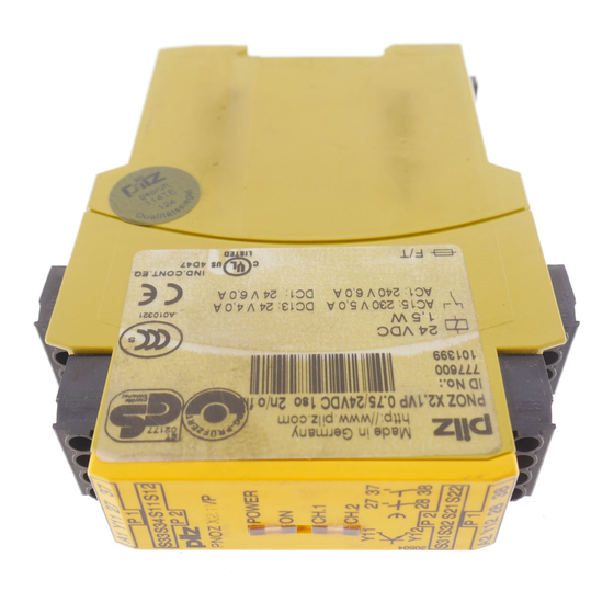
PNOZ X2.1VP
4
D
Betriebsanleitung
4
GB Operating instructions
4
F
Manuel d`utilisation
Sicherheitsbestimmungen
• Das Gerät darf nur von Personen
installiert und in Betrieb genommen
werden, die mit dieser Betriebsanleitung
und den geltenden Vorschriften über
Arbeitssicherheit und Unfallverhütung
vertraut sind. Beachten Sie die VDE-
sowie die örtlichen Vorschriften, insbe-
sondere hinsichtlich Schutzmaßnahmen.
• Beim Transport, der Lagerung und im
Betrieb die Bedingungen nach EN 60068-
2-6 einhalten (s. technische Daten).
• Durch Öffnen des Gehäuses oder eigen-
mächtige Umbauten erlischt jegliche Ge-
währleistung.
• Montieren Sie das Gerät in einen Schalt-
schrank; Staub und Feuchtigkeit können
sonst zu Beeinträchtigungen der Funktio-
nen führen.
• Sorgen Sie an allen Ausgangskontakten
bei kapazitiven und induktiven Lasten für
eine ausreichende Schutzbeschaltung.
• Die Sicherheitsfunktion muß mindestens
einmal im Monat ausgelöst werden.
Bestimmungsgemäße Verwen-
dung
Das Sicherheitsschaltgerät PNOZ X2.1VP ist
bestimmt für den Einsatz in
• NOT-AUS-Einrichtungen
• Sicherheitsstromkreisen nach VDE 0113
Teil 1 und EN 60204-1
(z. B. bei beweglichen Verdeckungen)
Das Gerät ist nicht für die Absicherung von
berührungslosen Verdeckungen geeignet, da
• kein dynamischer Start möglich ist.
• Gerät während dem Ablauf der Rückfall-
verzögerung gestartet werden kann.
Beachten Sie unbedingt die Sicherheitsab-
stände nach EN 294 und die Mindestabstän-
de nach EN 349.
Gerätebeschreibung
Das Sicherheitsschaltgerät PNOZ X2.1VP
ist in einem S-99-Gehäuse untergebracht.
Die Versorgungsspannung beträgt 24 V DC.
Merkmale:
• Relaisausgänge: 2 Sicherheitskontakte
(Schließer), zwangsgeführt, rückfall-
verzögert
• Anschlußmöglichkeit für NOT-AUS-Taster,
Schutztürgrenztaster und Starttaster
• Statusanzeigen
• Halbleiterausgang für Reglersteuerung
• Start während Ablauf der Rückfall-
verzögerung möglich
• Überwachung externer Schütze möglich
• keine galvanische Trennung
Das Schaltgerät erfüllt folgende Sicherheits-
anforderungen:
• Schaltung ist redundant mit Selbstüberwa-
chung aufgebaut.
• Sicherheitseinrichtung bleibt auch bei
Ausfall eines Bauteils wirksam.
AUDIN
Composants & systèmes d'automatisme
7 bis rue de Tinqueux - 51100 Reims - France
Tel. +33(0)326042021 • Fax +33(0)326042820
http://www.audin.fr • e-mail info@audin.fr
Safety Regulations
• The unit may only be installed and operated
by personnel who are familiar with both
these instructions and the current regulat-
ions for safety at work and accident
prevention. Follow VDE and local
regulations especially as regards
preventative measures.
• Transport, storage and operating
conditions should all conform to EN
60068-2-6.
• Any guarantee is void following opening of
the housing or unauthorised modifications.
• The unit should be panel mounted,
otherwise dampness or dust could lead to
function impairment.
• Adequate protection must be provided on
all output contacts especially with
capacitive and inductive loads.
• The safety function must be triggered at
least once a month.
Authorised Applications
The Safety Relay PNOZ X2.1VP is for use
in:
• Emergency Stop circuits
• Safety Circuits according to VDE 0113
part 1 and EN 60204-1
(e.g. with movable guards)
The unit is not suitable for use with non-
contact guards, e.g. ESPE as
• a dynamic start is not possible.
• the unit can be reset during delay-on de-
energisation.
Safety distances in accordance with EN 294
and minimum distances in accordance with
EN 349 must be observed.
Description
The Safety Relay PNOZ X2.1VP is enclosed
in a S-99 housing. The version available is
for 24 V DC operation only.
Features:
• Relay outputs: 2 safety contacts (N/O),
positive-guided, delay-on de-energised
• Connections for Emergency Stop Button,
Safety Gate Limit Switch and Reset
button
• Status Indicators
• Semiconductor output for variable
frequency inverter
• reset during delay-on de-energisation
possible
• Feedback Control Loop for monitoring of
external contactors/relays possible
• No galvanic separation
The relay complies with the following safety
requirements:
• The circuit is redundant with built-in self-
monitoring.
• The safety function remains effective in the
case of a component failure.
- 1 -
Conseils préliminaires
• La mise en oeuvre de l'appareil doit être
effectuée par une personne spécialisée en
installations électriques, en tenant compte
des prescriptions des différentes normes
applicables (NF, EN, VDE...) notamment
au niveau des risques encourus en cas de
défaillance de l'équipement électrique.
• Respecter les exigences de la norme
EN 60068-2-6 lors du transport, du
stockage et de l'utilisation de l'appareil.
• L'ouverture de l'appareil ou sa modification
annule automatiquement la garantie.
• L'appareil doit être monté dans une ar-
moire; l'humidité et la poussière pouvant
entraîner des aléas de fonctionnement.
• Vérifiez que le pouvoir de coupure des
contacts de sortie est suffisant en cas de
circuits capacitifs ou inductifs.
• La fonction de sécurité doit être activée au
moins une fois par mois.
Domaines d'utilisation
Le bloc logique de sécurité PNOZ X2.1VP est
adapté pour :
• les circuits d'arrêt d'urgence
• les circuits de sécurité selon les normes
NF 79-130 et EN 60-204/1 (ex. protecteurs
mobiles).
Le relais n'est pas adapté pour la
surveillance de barrages immatériels car
• un réarmement dynamique n'est pas
possible.
• le réarmement du relais est possible
pendant l'écoulement de la temporisation
à la retombée.
Veuillez respecter impérativement les
distances de sécurité d'après la
norme EN 294 et les distances minimales
d'après la norme EN 349.
Description de l'appareil
Inséré dans un boîtier S-99, le bloc logique
de sécurité PNOZ X2.1VP est alimenté en
24 V DC.
Particularités :
• Sorties disponibles : 2 contacts à
fermeture de sécurité, temporisés à la
retombée
• Bornes de raccordement pour poussoirs
AU, détecteurs de position et poussoir de
validation
• LEDs de visualisation
• Sortie statique pour variateur
• Le réarmement du relais est possible
pendant l'écoulement de la temporisation
à la retombée.
• Auto-contrôle des contacteurs externes
possible
• pas d'isolation galvanique
Le relais PNOZ X2.1VP répond aux
exigences suivantes :
• conception redondante avec auto-
surveillance
Werbung
Inhaltsverzeichnis

Verwandte Anleitungen für Pilz PNOZ X2.1VP


Inhaltszusammenfassung für Pilz PNOZ X2.1VP
- Seite 1 • Die Sicherheitsfunktion muß mindestens einmal im Monat ausgelöst werden. Bestimmungsgemäße Verwen- Authorised Applications Domaines d’utilisation The Safety Relay PNOZ X2.1VP is for use Le bloc logique de sécurité PNOZ X2.1VP est dung adapté pour : Das Sicherheitsschaltgerät PNOZ X2.1VP ist •...
- Seite 2 Funktionsbeschreibung Description du fonctionnement Function Description Das Schaltgerät PNOZ X2.1VP dient dem Le relais PNOZ X2.1VP assure de façon The relay PNOZ X2.1VP provides a safety- sicherheitsgerichteten Unterbrechen eines oriented interruption of a safety circuit. sure, l’ouverture d’un circuit de sécurité. A Sicherheitsstromkreises.
-
Seite 3: Mise En Oeuvre
• As the function for detecting shorts across • La fonction de détection de court-circuit est • Da die Funktion Querschlußerkennung the inputs is not failsafe, it is tested by Pilz testé par Pilz lors du contrôle final. Un test nicht einfehlersicher ist, wird sie von Pilz during the final control check. -
Seite 4: Anwendung
Emergency Stop wiring, safety gate control, différents cablages possibles du rungen, Reglersteuerung Kontakt- variable frequency inverter, contact expansion PNOZ X2.1VP : poussoirs AU, interrupteur de vervielfachung durch externe Schütze, sowie via external contactors as well as position, variateur, augmentation du nombre den Halbleiterausgang. -
Seite 5: Fehler - Störungen
Fehler - Störungen Faults Erreurs - Défaillances • Erdschluß • Earth fault • Défaut de masse Die Versorgungsspannung bricht zusam- The supply voltage fails and the safety La tension d’alimentation s’effondre et les men und die Sicherheitskontakte werden contacts are opened. An electronic fuse contacts de sortie s’ouvrent. -
Seite 6: Abmessungen In Mm /Dimensions In Mm /Dimensions En Mm
Schutzart/Protection/Indice de protection Einbauraum (z. B. Schaltschrank)/Mounting (eg. panel)/Lieu d'implantation (ex. armoire) IP54 Gehäuse/Housing/Boîtier IP40 Klemmenbereich/Terminals/Bornes IP20 Gehäusematerial/housing material/matériau du boîtier Gehäuse/Housing/Boîtier PPO UL 94 V0 Front/front panel/face avant ABS UL 94 V0 Max.Querschnitt des Außenleiters (Schraubklemmen)/Max. cable cross section (screw terminals)/Capacité... -
Seite 7: Steckbare Klemmen Abziehen
Lebensdauer der Ausgangsrelais/Service Life of Output relays/Durée de vie des relais de sortie AC1: 230 V DC13: 24 V DC1: 24 V AC15: 230 V 1000 10000 Schaltspielzahl x 10 3 Cycles x 10 3 Nombre de manœvres x 10 3 Steckbare Klemmen abziehen Remove plug-in terminals Démonter les borniers... - Seite 8 0224 2360180, Fax: 0224 2360184, E-Mail: pilz.tr@pilz.de Pilz Automation Safety L.P., 734 354-0272, Fax: 734 354-3355, E-Mail: info@pilzusa.com www.pilz.com ✆ Pilz GmbH & Co. KG, Sichere Automation, Felix-Wankel-Straße 2, 73760 Ostfildern, Deutschland, +49 711 3409-0, Fax: +49 711 3409-133, E-Mail: pilz.gmbh@pilz.de - 8 -...