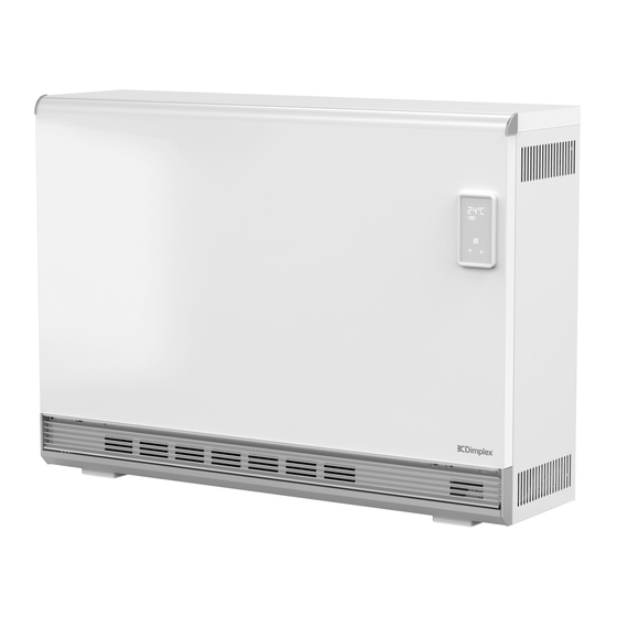
Dimplex VFE 20 Montage- Und Gebrauchsanweisungen
Wärmespeicher
Vorschau ausblenden
Andere Handbücher für VFE 20:
- Installations- und bedienungsanleitung (28 Seiten)

Verwandte Anleitungen für Dimplex VFE 20


Inhaltszusammenfassung für Dimplex VFE 20
- Seite 1 VFE 20 - VFE 70 Montage- und Gebrauchsanweisung Installation and Operating Instructions Wärmespeicher Storage heater X- 08/83039/0 Issue 3...
- Seite 2 Deutsch DE-2 2202/D www.dimplex.eu...
-
Seite 3: Inhaltsverzeichnis
Deutsch Inhalt Warnhinweise Funktion des Wärmespeichers Bedienfeld Lieferumfang Installationsort Montage Elektrischer Anschluss Inbetriebnahme Bedienung Wartung Störungen Garantie, Service Technische Daten www.dimplex.eu 2202/D DE-3... -
Seite 4: Warnhinweise
Ventilator! ACHTUNG! Wenn die Netzanschlussleitung dieses Gerä- tes beschädigt wird, muss sie durch eine qualifizierte Fachkraft ersetzt werden, um Gefährdungen zu vermeiden. Alle Angaben in mm ACHTUNG! Das Speicherheizgerät darf nicht unmittelbar unter einer Steckdose aufgestellt werden. DE-4 2202/D www.dimplex.eu... - Seite 5 Oberflächentemperatur 80 °C ACHTUNG! überschreiten. Besondere Aufmerksamkeit Reinigung und Benutzerwartung dürfen muss der Anwesenheit von Kindern und nicht von Kindern ohne Beaufsichtigung schutzbedürftigen Personen gewidmet wer- durchgeführt werden. den. HINWEIS Verwenden Sie keine Dampfgeräte zur Reinigung des Speicherheizgerätes. www.dimplex.eu 2202/D DE-5...
-
Seite 6: Funktion Des Wärmespeichers
GB2487781, GB2500736, GB2511538, GB2526552 Raumabhängige Aufladung (Auto Mode) International: EP2830832,EP2831688, EP2965166, Wenn dieser Modus aktiviert ist, berechnet die Lade- EP3132324, WO2011154521, WO2013144170, elektronik die Lademenge basierend auf den Raum- WO2014135667, WO2015181136 temperaturbedingungen, um den Wärmebedarf des Benutzers bestmöglich zu erfüllen. DE-6 2202/D www.dimplex.eu... -
Seite 7: Bedienfeld
Optionale Einstellungen wie: Uhrzeit/Datum Fensterüberwachung, Tastenton, 3.1. Tastenfunktionen Bluetooth® (drahtlose Verbindung für den Installa- MENÜ teur bei Verwendung der Dimplex ConfigR App), Zusatzheizung Ein/Aus Rücksetzen auf Werkseinstellung. Timer (Wochenprogramm) Frostschutztemperatur 7° C Installateur-Menü ... -
Seite 8: Lieferumfang
Gegenstände aller Art müssen mindestens 30 stellt werden, im Falle von Vinyl- oder Parkettböden cm vom Luftaustrittsgitter entfernt sein. Gleiches gilt oder Böden mit hellen Teppichen kann aber die Bo- auch für Langflorteppiche. denfarbe im Bereich der Standfüße durch Druck- oder DE-8 2202/D www.dimplex.eu... -
Seite 9: Montage
6.2 Die beiden seitlichen Wandanschlussleisten an der Rückseite des Gerätes befestigen. Obere Wand- anschlussleiste an den beiden seitlichen Wandan- schlussleisten festschrauben. 6.4 Verbindungsleitung ausstecken. HINWEIS Legen Sie die Vorderwand und die Seitenwände auf eine weiche, saubere Oberfläche, um Lackschäden zu vermeiden. www.dimplex.eu 2202/D DE-9... - Seite 10 Keine Gegenstände auf das Heizgerät stellen. 6.8 Erste Reihe der Speichersteine unterhalb des Heizelements in den Kernraum schieben, beginnend von rechts. Darauf achten, dass die Vertiefungen in den Speicher- steinen zur Aufnahme des Heizkörpers immer nach oben zeigen. DE-10 2202/D www.dimplex.eu...
- Seite 11 Zwischenwand aufliegen. Seitliche Kante (B) hinter den Umbug der Zwischenwand schie- ben. Rechts: Seitliche Kante der Kernraumabdeckung (C) zwischen Wärmedämmung und Zwischenwand ein- führen. Auf Führungsschlitze achten. Kernraumabdeckung fest andrücken und mit den drei Schrauben befestigen. www.dimplex.eu 2202/D DE-11...
-
Seite 12: Elektrischer Anschluss
Gehäuseteile wieder anbringen, umgekehrter Vor- gang der Demontage. HINWEIS Ziehen Sie die Schrauben mit dem geeigneten Dreh- moment (max. 1,2 Nm) an. 7.1 Sicherungsschraube (A) herausdrehen und Hauptelektronik nach unten klappen (B), um Zugang zu den Anschlussklemmen zu erhalten. DE-12 2202/D www.dimplex.eu... - Seite 13 Das Gerät muss geerdet werden. In der elektrischen Installation ist eine Trennvorrich- tung vorzusehen mit mindestens 3 mm Kontaktöff- HINWEIS nung an jedem Pol (z.B. Sicherungsautomat). An den Klemmen N-R und L-R muss eine Dauerspan- nung 230 V ~ anliegen. www.dimplex.eu 2202/D DE-13...
-
Seite 14: Inbetriebnahme
22:00 Uhr 22:00 Uhr Taste MENÜ, ENTER und ZURÜCK ca. drei Sekun- den lang gedrückt halten. PIN-Code 0000 blinkt. PIN-Code vier mal mit Taste ENTER bestätigen. Anzeige P9 blinkt. Anzeige P9 auswählen. P9 blinkt. DE-14 2202/D www.dimplex.eu... - Seite 15 Taste ENTER drücken. Anzeige WSG erscheint. OFF blinkt. HINWEIS Nur bei Betrieb an Zentralsteuergerät ZWU 06E: Wurde der Einsatzbereich „WSG Intelligent“ gewählt (siehe Standardanzeige) muss auf WSG ON gestellt werden (ON blinkt). Taste ENTER drücken. Einstellung abgeschlossen. www.dimplex.eu 2202/D DE-15...
- Seite 16 Je nach Version wird dieser Menüpunkt angezeigt A2 ON auf 14:00 und A2 OFF auf 16:00 stellen. oder nicht. Einstellwerte nicht verändern! A3 ON auf 22:00 und A3 OFF auf 23:59 stellen. A4 ON und A4 OFF bleiben auf 23:59. DE-16 2202/D www.dimplex.eu...
- Seite 17 Mit den Tasten Anpassung vornehmen (Be- Taste ENTER drücken. ON blinkt. reich -50% bis +50%). Wert blinkt. Mit Tasten OFF auswählen. OFF blinkt. Taste ENTER drücken. Einstellung abgeschlossen. Taste ENTER drücken. Einstellung abgeschlossen. www.dimplex.eu 2202/D DE-17...
-
Seite 18: Bedienung
Wärme über den Lüfter abgeben kann. Taste MENÜ drücken. P0 wird angezeigt, an- schließend blinkt der eingestellte Prozentwert (100 = maximale Aufladung) Taste betätigen bis Anzeige AUTO blinkt. Raumabhängige Aufladung ist aktiviert. DE-18 2202/D www.dimplex.eu... -
Seite 19: Hauptmenü
Symbol ZUSATZHEIZUNG blinkt. Taste ENTER drücken. ON blinkt. Taste drücken. OFF blinkt. Taste ENTER drücken. Einstellung abgeschlossen. HINWEIS Wird die Zusatzheizung über ein wandmontiertes Raumthermostat angesteuert, muss das Umbau-Set Artikelnummer: 459270.28.61 eingebaut werden. www.dimplex.eu 2202/D DE-19... - Seite 20 Taste ENTER betätigen. P1 (Programm 1) blinkt. Die Anzeige wechselt zum Hauptmenü. Taste ENTER drücken. Einschaltzeit blinkt. Taste MENÜ drücken. Mit Tasten Stunden einstellen. Symbol ZUSATZHEIZUNG blinkt. Taste ENTER betätigen. Minutenanzeige blinkt. DE-20 2202/D www.dimplex.eu...
-
Seite 21: Erweitertes Menü
HINWEIS Taste ENTER drücken. Symbol OFF blinkt. Wird kein automatischer Wechsel Sommer/Winterzeit Taste drücken. ON blinkt. gewünscht, bei Anzeige dSt mit den Tasten Taste ENTER drücken. Einstellung abgeschlossen. Position OFF einstellen. www.dimplex.eu 2202/D DE-21... - Seite 22 Sekunden lang gedrückt halten. Mit Tasten Anzeige P7 auswählen. P7 blinkt. Taste ENTER drücken. 0 °C blinkt. Mit Tasten Korrekturwert einstellen. Taste ENTER drücken. Einstellung abgeschlossen. DE-22 2202/D www.dimplex.eu...
-
Seite 23: Tastensperre
Taste ENTER drücken. Programm wird auf Werks- einstellung zurückgesetzt. HINWEIS Im Anschluss muss die aktuelle Zeit, das Datum und die Funktion Sommer/Winterzeit neu eingestellt wer- den, siehe „Zeit und Datum einstellen“ auf Seite 21. www.dimplex.eu 2202/D DE-23... -
Seite 24: Wartung
Riegel (A) nach innen schieben, gleichzeitig kleine Münze in Aufnahme (Unterseite Bedienfeld) ein- setzen und verdrehen. Batteriefach herausziehen (B). Knopfzelle herausziehen und wechseln (C). Auf Polarität achten (+ Pol wie dargestellt). Zusammenbau in umgekehrter Reihenfolge. DE-24 2202/D www.dimplex.eu... -
Seite 25: Störungen
Hausmüll entsorgt werden, sondern müs- Seitenwand öffnen, Siehe „Montage“ auf Seite 9. sen einer örtlichen Entsorgungsstelle zuge- führt werden. Ausgebaute Speichersteine bitte während der gesam- ten Entsorgungskette trocken lagern, da sonst Spu- renelemente ins Grundwasser gelangen können. www.dimplex.eu 2202/D DE-25... -
Seite 26: Garantie, Service
Service Kontakt Die Robert Bosch Hausgeräte GmbH führt in unserem Glen Dimplex Deutschland GmbH Auftrag den Service für Dimplex Geräte durch. Am Goldenen Feld 18 95326 Kulmbach Bitte halten Sie vor der Kontaktierung unseres Kun- Telefon: +49 9221 709 700... -
Seite 27: Technische Daten
B x H x T 6 x Kolli 400 V, 3 N~ 622 x 664 x 250 VFE 20 K HFR 220 2000 W 16 kWh 127 kg 38 kg 50 Hz 9 x Kolli 400 V, 3 N~... - Seite 28 Deutsch Technische Daten 13.3. Energierelevante Daten DE-28 2202/D www.dimplex.eu...
- Seite 29 Deutsch Glen Dimplex Deutschland GmbH Telefon: +49 9221 709 700 Am Goldenen Feld 18 Telefax: +49 9221 709 701 E-Mail: elektroheizung@dimplex.de 95326 Kulmbach www.dimplex.eu 2202/D DE-29...
- Seite 30 English EN-2 2202/D www.dimplex.eu...
- Seite 56 English Glen Dimplex Deutschland GmbH Phone: +49 9221 709 700 Am Goldenen Feld 18 Fax: +49 9221 709 701 E-mail: elektroheizung@dimplex.de 95326 Kulmbach EN-28 2202/D www.dimplex.eu...