Herunterladen Inhalt Inhalt Diese Seite drucken
JUMO dTRANS p33 Betriebsanleitung
Vorschau ausblenden Andere Handbücher für dTRANS p33:
Inhaltsverzeichnis

Werbung

Verfügbare Sprachen

Verfügbare Sprachen

JUMO dTRANS p33
Betriebsanleitung
Operating Manual
Notice de mise en service
40475300T90Z000K000
V5.00/DE-EN-FR/00089504/2021-12-09

Werbung

Inhaltsverzeichnis
loading

Inhaltszusammenfassung für JUMO dTRANS p33

  • Seite 1 JUMO dTRANS p33 Betriebsanleitung Operating Manual Notice de mise en service 40475300T90Z000K000 V5.00/DE-EN-FR/00089504/2021-12-09...
  • Seite 3 JUMO dTRANS p33 Druckmessumformer oder Pegelsonde für den Einsatz im Ex-Bereich II 1/2G Ex ia IIC T6 ... T4 Ga/Gb (ohne Typenzusatz 406, 407) II 1/2D Ex ia IIIC T60 °C ... T100 ° C Da/Db (ohne Typenzusatz 406, 407) II 2G Ex ia IIC T6 ...
  • Seite 4 Weitere Informationen und Downloads qr-404753-de.jumo.info...
  • Seite 5 Inhalt Inhalt Sicherheitshinweise ......... . 5 Warnende Zeichen .
  • Seite 6 Inhalt Elektrische Daten ............29 Mechanische Eigenschaften .
  • Seite 7: Sicherheitshinweise

    Sicherheitshinweise 1 Sicherheitshinweise Warnende Zeichen GEFAHR! Dieses Zeichen weist darauf hin, dass ein Personenschaden durch Stromschlag eintreten kann, wenn die entsprechenden Vorsichtsmaßnahmen nicht getroffen werden. VORSICHT! Dieses Zeichen in Verbindung mit dem Signalwort weist darauf hin, dass ein Sachschaden oder ein Datenverlust auftritt, wenn die entsprechenden Vorsichtsmaßnahmen nicht getroffen werden.
  • Seite 8: Einleitung

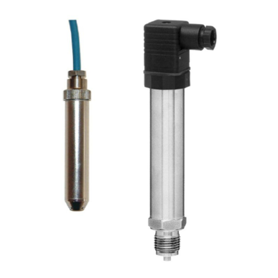
    Einleitung 2 Einleitung Der Druckmessumformer misst den Druck nichtaggressiver und aggressiver Gase, Dämpfe, Flüssigkei- ten und Stäube. Er arbeitet nach dem piezoresistiven Messprinzip. Das Ausgangssignal ist ein einge- prägter Gleichstrom, der dem Eingangsdruck linear proportional ist. Der Druckmessumformer erfüllt folgende Anforderungen der Explosionsgruppe II: •...
  • Seite 9: Geräteausführung Identifizieren

    Geräteausführung identifizieren 3 Geräteausführung identifizieren Typenschild Beispiele Abb. 3-1 Grundgerät mit Typenzusatz EAC Ex Abb. 3-2 Grundgerät mit Typenzusatz 240 und 406 Abb. 3-3 Grundgerät mit Typenzusatz 240 und 407...
  • Seite 10 3 Geräteausführung identifizieren Abb. 3-4 Rückansicht Grundgerät mit Typenzusatz EAC Ex HINWEIS! Weitere Angaben zu zulässigen Temperaturen und höchstzulässige zugeführte Leistung siehe „zulässi- ge Temperaturen Gas“, Seite 32.
  • Seite 11 3 Geräteausführung identifizieren Bestellangaben Grundtyp 404753/000 JUMO dTRANS p33 – Druckmessumformer oder Pegelsonde für den Einsatz im Ex-Bereich 404753/004 JUMO dTRANS p33 – Druckmessumformer oder Pegelsonde für den Einsatz im Ex-Bereich, für erhöhte Messstofftemperaturen bis 200 °C Eingang 0 bis 0,25 bar Relativdruck...
  • Seite 12 3 Geräteausführung identifizieren Prozessanschluss G 1/4 DIN EN 837 G 1/2 DIN EN 837 1/4-18 NPT DIN EN 837 1/2-14 NPT DIN EN 837 G 1/2 DIN 3852-11 Pegelsonde: G 1/4 innen G 3/4 frontbündig DIN EN ISO 228-1 G 1/2 frontbündig mit 2-fach-Dichtung G 3/4 frontbündig mit 2-fach-Dichtung G 1 frontbündig mit 2-fach-Dichtung Kegelstutzen mit Überwurfmutter DN 20 DIN 11851 (Milchrohrverschraubung)
  • Seite 13: Lieferumfang

    3 Geräteausführung identifizieren Bestellschlüssel Bestellbeispiel 404753/000 - 504 - - 61 - Lieferumfang 1 Gerät in bestellter Ausführung 1 Betriebsanleitung Zubehör Bezeichnung Teile-Nr. Leitungsdose, 4-polig, M12 × 1, gerade, 2 m 00404585 Leitungsdose, 4-polig, M12 × 1, gewinkelt, 2 m 00409334 Klemmgehäuse mit Druckausgleichselement 00061206...
  • Seite 14: Abmessungen

    Montage 4 Montage Abmessungen 4.1.1 Elektrischer Anschluss festes Anschlusskabel Rundstecker M12 × 1 Leitungsdose Anschlusskopf...
  • Seite 15: Prozessanschlüsse, Nicht Frontbündig

    4 Montage Typenzusatz 406 Typenzusatz 407 Grundtypergänzung 004 Pegelsonde: Schutzart IP68, Pegelsonde: Schutzart IP68, für erhöhte Mediumstemperatur festes Anschlusskabel, festes Anschlusskabel, Kategorie 2G, Zone 1 Kategorie 1G, Zone 0 festes Anschlusskabel kundenseitiges Schutzrohr, siehe Betriebsanleitung 4.1.2 Prozessanschlüsse, nicht frontbündig G 1/4 G 1/2 1/4-18 NPT 1/2-14 NPT...
  • Seite 16 4 Montage 4.1.3 Prozessanschlüsse, frontbündig G 3/4 G 1/2 mit 2-fach Dichtung G 3/4 mit 2-fach Dichtung Profildichtring DN G 1/2 O-Ring 14 × 1.78 Profildichtring DN G 3/4 O-Ring 20.35 × 1.78 603 bis 607 612, 613, 616 Kegelstutzen Klemmstutzen Tankanschluss mit Nut- VARIVENT-Anschluss...
  • Seite 17: Prozessanschlüsse Pegelsonden

    4 Montage 4.1.4 Prozessanschlüsse Pegelsonden (Typenzusätze 406, 407) Anschluss unten geschlossen Anschluss unten offen G 1/4 innen Schutzkappe...
  • Seite 18 Zugentlastung. Die Verwendung des Kabelhalters stellt sicher, dass das Kabel nicht unzulässig deformiert wird. Der Kabelhalter ist kompatibel zu allen JUMO-Pegelsonden. Der Spannbereich ist 4,8 bis 10 mm. Die Zugfestigkeit beträgt maximal 390 N. Der Kabelhalter besteht aus UV-beständigem, korrosionsfreiem und glasfaserverstärktem Polyamid. Die mittigen Langlöcher sind zur optionalen, anwendungsabhängigen Fixierung des Kabels vorgesehen, um...
  • Seite 19: Klemmgehäuse Mit Druckausgleichselement

    4 Montage 4.2.3 Klemmgehäuse mit Druckausgleichselement Das Klemmgehäuse, Teile-Nr. 00061206, dient zur sicheren Installation des Pegelsondenkabels. Das Ende des Druckausgleichsschlauches wird stets vor Niederschlag und Kondensat geschützt (IP65). Die weitere Verteilung kann mit einem standardisierten Kabel ohne Druckausgleichsschlauch ausgeführt werden. Das Klemmgehäuse sollte zur optimalen und kostengünstigen Realisierung des Systems so nah wie möglich zur Messstoffoberfläche außerhalb des Messstoffes montiert werden.
  • Seite 20: Ex-I Speise- Und Eingangstrennverstärker

    4 Montage 4.2.5 Ex-i Speise- und Eingangstrennverstärker Der Ex-i Speise- und Eingangstrennverstärker, Teile-Nr. 00577948, ist für den Betrieb von im Ex-Bereich installierten eigensicheren (Ex-i) Messumformern und mA-Stromquellen ausgelegt. Zweileiter-Messum- former werden mit Energie versorgt und analoge 0/4 bis 20 mA-Messwerte aus dem Ex-Bereich in den Nicht-Ex-Bereich übertragen.
  • Seite 21: Montageort Und Umgebungsbedingungen

    4 Montage Montageort und Umgebungsbedingungen GEFAHR! Der Druckmessumformer entspricht nicht den Anforderungen „Ausrüstungsteil mit Sicherheits- funktion“ gemäß Druckgeräte-Richtlinie 2014/68/EU.  Bei gefährlichen Messstoffen, z. B. Sauerstoff, Acetylen, brennbaren und giftigen Stoffen, sowie bei Kälteanlagen, Druckbehältern usw. sind die bestehenden einschlägigen Vorschriften zu beachten! Die nationalen und internationalen Sicherheits- und Unfallverhütungsvorschriften müssen beachtet werden! Nichtbeachten dieser Vorschriften kann Personen- oder Sachschäden verursachen!
  • Seite 22 4 Montage Montagebeispiel 1 Montagebeispiel 2 Messstofftemperatur max. 200 °C Gehäusetemperatur max. 95 °C Isolierung...
  • Seite 23: Leitungsanschluss Im Anschlusskopf

    4 Montage Druckanschluss Dichtungen GEFAHR! Bei der Zündschutzart Eigensicherheit muss bei entsprechendem Prozessanschluss eine Flach- dichtung, z. B. nach DIN EN 837, verwendet werden!  Nach Herstellen des Druckanschlusses muss dieser auf Dichtheit geprüft werden! Wenn der Druckmessumformer in eine Gewindebohrung eingeschraubt wird, muss die volle Länge des Gewindes des Druckmessumformers im Einsatz sein! HINWEIS! Das richtige Anzugsmoment ist abhängig von Größe, Werkstoff und Form der verwendeten Dichtung so-...
  • Seite 24: Montage Der Anschlussdose

    4 Montage Montage der Anschlussdose Leitungsdose nach DIN 43650, Bauform AF mit Pg9-Verschraubung für Leitungsdurchmesser von 4,5 bis 7 mm; Leitungsquerschnitt bis maximal 1,5 mm , Schutzart IP65 nach DIN EN 60529 Innenteil Außenteil Schraube 1. Zum Öffnen des Steckers die Schraube (C) herausdrehen. 2.
  • Seite 25: Montagehinweise Für Die Pegelsonde

    4 Montage Montagehinweise für die Pegelsonde (Typenzusatz 407) Besondere Bedingungen Die besonderen Bedingungen beziehen sich nur auf den Typenzusatz 407 für den Einsatz in Zone 0. Das Gesamtsystem seitens des Betreibers ist so zu wählen, dass eine anwendungsgerechte Zonentren- nung gewährleistet ist. Dieses muss durch Einbeziehung eines Schutzrohres und Verschraubungen ge- mäß...
  • Seite 26 4 Montage Montage am Schutzrohr 1. Das Gewinde und den Konus des Verschraubungsstutzens sowie das Gewinde der Überwurfmutter der Geraden Verschraubung (zweiseitige Schneidringverschraubung) schmieren. Die Schmierpaste ist anwendungsgerecht zu wählen. 2. Ersten Rohrabschnitt über das Kabel in Richtung elektrischen Anschluss des Messinstrumentes schieben.
  • Seite 27 4 Montage Die Verschraubungen müssen gemäß DIN EN 60079-1 • mindestens 5 befindliche Gewindegänge im Eingriff • eine Gewindesteigung ≥ 0,7 mm • sowie eine Einschraubtiefe von ≥ 0,8 mm bei einem Gehäusevolumen mehr als 100 cm aufweisen und sollen folgende Eigenschaften besitzen: •...
  • Seite 28 4 Montage Hinweise zum Einsatz nach EHEDG Folgende Prozessanschlüsse sind für den Einsatz nach EHEDG geeignet: • 613 und 616 (Clamp DN25/32/40/50 mit Tri-Clamp-Dichtungen Combifit International B.V.) • 685 (VARIVENT in-line flange connection Typ B, F und N mit O-Ring aus EPDM) Das Gerät ist bei entsprechender Installation für CIP (cleaning in place) geeignet, Temperatur- und Werkstoffbeständigkeit siehe Kapitel 6 „Technische Daten“, Seite 29.
  • Seite 29: Elektrischer Anschluss

    Elektrischer Anschluss 5 Elektrischer Anschluss HINWEIS! Stellen Sie einen äußeren Defekt – auch mechanischer Art – fest, ist das Gerät zur Reparatur an den Hersteller zu senden. Installationshinweise GEFAHR! Beim elektrischen Anschluss sind die einschlägigen Bestimmungen zu beachten: - Verordnung über elektrische Anlagen in explosionsgefährdeten Räumen (Elex V) - Bestimmung für das Errichten elektrischer Anlagen in explosionsgefährdeten Bereichen - EG-Baumusterprüfbescheinigung ...
  • Seite 30 5 Elektrischer Anschluss Allgemeine Hinweise • maximale Leitungslänge 50 m • minimaler Biegeradius 120 mm (bei fester Verlegung) • die Leitung darf nicht zusammengedrückt werden • das Leitungsende vor Feuchtigkeitseintritt schützen • bei der Verlängerung der Leitung auf Druckausgleich achten •...
  • Seite 31: Allgemein

    Technische Daten 6 Technische Daten Allgemein Referenzbedingungen gemäß DIN 16086 und DIN IEC 770/5.3 Nennlage beliebig Eingang Umgebungstemperatureinfluss für Messbereiche 0,25 und 0,4 bar Nullpunkt ≤ 0,03 %/K typisch, ≤ 0,05 %/K max. Messspanne (MSP) ≤ 0,02 %/K typisch, ≤ 0,04 %/K max. für Messbereiche ab 0,6 bar Nullpunkt ≤...
  • Seite 32: Mechanische Eigenschaften

    6 Technische Daten Mechanische Eigenschaften Werkstoff Gehäuse Edelstahl 304 druckmittelberührte Teile Standard Edelstahl 316 L, 316 Ti bei Messbereich ≥ 60 bar Edelstahl 316 Ti, 630 bei Typenzusatz 406 Kabelmaterial PE (Polyethylen), Standard Gewicht 350 g bei Prozessanschluss G 1/2 Umwelteinflüsse Umgebungstemperatur -40 bis +85 °C...
  • Seite 33: Zulassungen Und Prüfzeichen

    6 Technische Daten Zulassungen und Prüfzeichen ATEX Prüfstelle Eurofins Electrosuisse Product Testing AG Zertifikat/Prüf-Nr. SEV 09 ATEX 0140 X Prüfgrundlage EN 60079-0, EN 60079-11, EN 60079-26 gilt für Typ 404753 EHEDG Prüfstelle Research Center Weihenstephan for Brewing and Food Quality Zertifikat/Prüf-Nr.
  • Seite 34: Auszug Aus Der Baumusterprüfbescheinigung

    6 Technische Daten 6.6.1 Auszug aus der Baumusterprüfbescheinigung zulässige Medien Das Gerät mit Typenzusatz 407 darf in folgenden Medien eingesetzt werden: Diesel (blaugefärbt) Pflanzenöl Biodiesel Diesel mit 5 bis 20 % Biodieselbei- Diesel Heizöl extra leicht, leicht, mittel mengung Heizöl schwefelarm bleifreies Benzin Heizöl additiviert Methylalkohol (rein, für motorische...
  • Seite 35: Wartung, Reinigung Und Rücksendung

    Wartung, Reinigung und Rücksendung 7 Wartung, Reinigung und Rücksendung Wartung Das Gerät ist wartungsfrei. Im Reparaturfall das Gerät bitte sauber und vollständig zurücksenden. Für die Rücksendung die Origi- nalverpackung verwenden. HINWEIS! Wenn der Druckmessumformer im staubexplosionsgefährdeten Bereich in Zone 20, 21 oder 22 einge- setzt wird, muss er, bei ungünstiger Einbaulage oder ungünstigem Einbauort, regelmäßig vom Staub be- freit werden.
  • Seite 36: Eu-Konformitätserklärung

    EU-Konformitätserklärung EU declaration of conformity / Déclaration UE de conformité Dokument-Nr. CE 696 Document No. / Document n°. Hersteller JUMO GmbH & Co. KG Manufacturer / Etabli par Anschrift Moritz-Juchheim-Straße 1, 36039 Fulda, Germany Address / Adresse Produkt Product / Produit Name Typenblatt-Nr.
  • Seite 37: Konformitätserklärung

    8 Konformitätserklärung Angewendete Normen/Spezifikationen Standards/Specifications applied / Normes/Spécifications appliquées Fundstelle Ausgabe Bemerkung Reference / Référence Edition / Édition Comment / Remarque EN 61326-1 2013 EN 61326-2-3 2013 Gültig für Typ Valid for Type / Valable pour le type 404753/... Richtlinie 2 Directive / Directive Name ATEX...
  • Seite 38 8 Konformitätserklärung EU-Baumusterprüfbescheinigung 2.1 EU type examination certificate / Certificat d'examen de type UE Fundstelle SEV 09 ATEX 0140 X Reference / Référence Benannte Stelle Eurofins Electrosuisse Product Testing AG Notified Body / Organisme notifié Kennnummer 1258 Identification no. / N° d'identification Anerkannte Qualitätssicherungssysteme der Produktion Recognized quality assurance systems of production / Systèmes de qualité...
  • Seite 39 8 Konformitätserklärung Gültig für Typ Valid for Type / Valable pour le type 404753/... Aussteller JUMO GmbH & Co. KG Issued by / Etabli par Ort, Datum Fulda, 2018-01-03 Place, date / Lieu, date Rechtsverbindliche Unterschrift Bereichsleiter Verkauf Legally binding signature / Signature juridiquement valable ppa.
  • Seite 40 Baumusterprüfbescheinigung 9 Baumusterprüfbescheinigung...
  • Seite 41: Baumusterprüfbescheinigung

    9 Baumusterprüfbescheinigung...
  • Seite 42 9 Baumusterprüfbescheinigung...
  • Seite 43 9 Baumusterprüfbescheinigung...
  • Seite 44: China Rohs

    China RoHS 10 China RoHS...
  • Seite 46 JUMO GmbH & Co. KG Moritz-Juchheim-Straße 1 Technischer Support Deutschland: 36039 Fulda, Germany Telefon: +49 661 6003-715 Telefon: +49 661 6003-9135 Telefax: +49 661 6003-606 Telefax: +49 661 6003-881899 E-Mail: mail@jumo.net E-Mail: support@jumo.net Internet: www.jumo.net Lieferadresse: Mackenrodtstraße 14 36039 Fulda, Germany...
  • Seite 47 JUMO dTRANS p33 Pressure Transmitter or Level Probe for use in hazardous areas Operating Manual 40475300T90Z000K000 EN/00089504/2021-12-09...
  • Seite 48 Further information and downloads qr-404753-en.jumo.info...
  • Seite 49 Contents Contents Safety information..........5 Warning symbols.
  • Seite 50 Contents Electrical data ............29 Mechanical features .
  • Seite 51: Safety Information

    Safety information 1 Safety information Warning symbols DANGER! This symbol indicates that personal injury from electrocution may occur if the appropriate precaution- ary measures are not taken. CAUTION! This symbol in connection with the signal word indicates that material damage or data loss will occur if the respective precautionary measures are not taken.
  • Seite 52 Introduction 2 Introduction The pressure transmitter measures the pressure in both corrosive and non-corrosive gases, vapors, liq- uids and dusts. It operates on the piezoresistive measuring principle. The output signal is a DC current that is proportional to the input pressure. The pressure transmitter fulfills the following requirements for equipment group II: •...
  • Seite 53: Identifying The Device Version

    Identifying the device version 3 Identifying the device version Nameplate Example Fig. 3-1 Basic device with extra code EAC Ex Fig. 3-2 Basic device with extra code 240 and 406 Fig. 3-3 Basic device with extra code 240 and 407...
  • Seite 54 3 Identifying the device version Fig. 3-4 Rear view basic device with extra code EAC Ex NOTE! For further details reated to permissible temperature and „maximum permissible supplied power, see "Permissible temperatures gas", Page 32.
  • Seite 55: Order Details

    Order details Basic type 404753/000 JUMO dTRANS p33 – Pressure transmitter or level probe for use in hazardous areas 404753/004 JUMO dTRANS p33 – Pressure transmitter or level probe for use in hazardous areas, for elevated medium temperatures up to 200 °C Input 0 to 0.25 bar relative pressure...
  • Seite 56 3 Identifying the device version Process connection G 1/4 to DIN EN 837 G 1/2 to DIN EN 837 1/4-18 NPT to DIN EN 837 1/2-14 NPT to DIN EN 837 G 1/2 to DIN 3852-11 Level probe: G 1/4 internal G 3/4 front-flush to DIN EN ISO 228-1 G 1/2 front-flush with 2×...
  • Seite 57 3 Identifying the device version Order code Order example 404753/000 - 504 - - 61 - Scope of delivery 1 Pressure Transmitter and Level Probe in ordered version 1 Operating Instructions Accessories Designation Part no. Line socket, 4-pole, M12 × 1, straight, 2 m 00404585 Line socket, 4-pole, M12 ×...
  • Seite 58 Mounting 4 Mounting Dimensions 4.1.1 Electrical connection Attached cable Round plug M12 × 1 Cable socket Terminal head...
  • Seite 59 4 Mounting Extra code 406 Extra code 407 Basic type extension 004 Level probe: IP68 protection, Level probe: IP68 protection, for elevated temperature of medium attached cable, attached cable, class 2G, zone 1 class 1G, zone 0 Attached connecting cable Customer-supplied protection tube, see Operating Instructions 4.1.2 Process connections, not front-flush...
  • Seite 60 4 Mounting 4.1.3 Process connections, front-flush G 3/4 G 1/2 with 2× seal G 3/4 with 2× seal Profile seal DN G 1/2 O-ring 14 × 1.78 Profile seal DN G 3/4 O-ring 20.35 × 1.78 603 to 607 612 bis 616 Taper socket Clamping socket Tank connection with union...
  • Seite 61 4 Mounting 4.1.4 Process connection for level probes (extra codes 406, 407) Connection closed underneath Connection open underneath G 1/4 internal Protective cap...
  • Seite 62: Accessories

    Use of the wire holder ensures that the cable is not deformed in an unacceptable manner. The wire holder is compatible with all JUMO level probes. The clamping range is 4.8 to 10 mm. The maximum tensile strength is 390 N.
  • Seite 63 4 Mounting 4.2.3 Terminal case with pressure compensation element The terminal case, part no. 00061206, is used for secure installation of the level probe cable. The end of the pressure equalization hose is always protected from deposits and condensation (IP65). The re- maining distribution can be performed with a standard cable without a pressure equalization hose.
  • Seite 64 4 Mounting 4.2.5 Ex-i repeater power supply / input isolating amplifier The Ex-i repeater power supply / input isolating amplifier, part no. 00577948, is designed for operating intrinsically safe transmitters (Ex-i) and mA current sources installed in potentially explosive (Ex) areas. Two-wire transmitters are supplied with energy and analog 0/4 to 20 mA measured values are transmit- ted from the Ex-area to the non-Ex-area.
  • Seite 65 4 Mounting Mounting site and environmental conditions DANGER! The pressure transmitter does not meet the "Equipment with safety function" requirements ac- cording to the Pressure Equipment Directive 2014/68/EU.  The current relevant regulations must be observed for dangerous media, e.g. oxygen, acetylene, flammable, and poisonous substances, as well as for cooling systems and pressure tanks etc.
  • Seite 66 4 Mounting Mounting example 1 Mounting example 2 Temperature of medium 200 °C max. Housing temperature 95 °C max. Insulation...
  • Seite 67: Pressure Connection

    4 Mounting Pressure connection Seals DANGER! A flat seal, e.g. according to DIN EN 837, must be used for the appropriate process connection for the ignition protection type intrinsic safety!  The pressure connection must be checked for seal tightness once established! If the pressure transmitter is screwed into a threaded hole, the full length of the thread of the pres- sure transmitter must be used! NOTE!
  • Seite 68 4 Mounting Assembly of the terminal box Terminal box to DIN 43650, Form AF with Pg9 gland for cable diameters from 4.5 to 7 mm; maximum conductor cross-section 1.5 mm , IP65 protection to EN 60529 Inner part Outer part Screw 1.
  • Seite 69: Special Conditions

    4 Mounting Mounting instructions for pressure transmitters (extra code 407) Special conditions The special conditions refer only to extra code 407 for use in zone 0. The entire system must be selected by the operator in such a way as to ensure that zones are separated properly for the application.
  • Seite 70 4 Mounting Mounting on the protection tube 1. Lubricate the thread and taper of the screw connection adapter and the thread of the union nut of the straight screw connection (two-sided cutting ring connection). Select an appropriate lubrication paste for the application. 2.
  • Seite 71 4 Mounting The screw connections must be in accordance with DIN EN 60079-1 • At least 5 threads engaged • Pitch of one thread ≥ 0.7 mm • A screw-in depth of ≥ 0.8 mm with an enclosure volume of more than 100 cm The screw connection should have the following characteristics: •...
  • Seite 72 4 Mounting Important information for usage according to EHEDG The following process connections are suitable for use according to EHEDG: • 613 and 616 (Clamp DN 25/32/40/50 with Tri-Clamp seals Combifit International B.V.) • 685 (VARIVENT in-line flange connection type B, F, and N with O-ring made of EPDM) The device is suitable for CIP (cleaning in place) if installed appropriately, for temperature and material resistance see chapter 6 "Technical data", Page 29.
  • Seite 73: Electrical Connection

    Electrical connection 5 Electrical connection NOTE! If you determine an external defect – also a mechanical way – the differential pressure transmitter has to be sent for repair to the manufacturer. Installation notes DANGER! When making the electrical connection, the relevant regulations must be observed: - Regulations concerning electrical apparatus in hazardous areas (Elex V) - Regulations on the installation of electrical apparatus in hazardous areas - EC-type-examination certificate...
  • Seite 74: Connection Diagram

    5 Electrical connection General notes • Maximum cable length 50 m • Minimum bending radius 120 mm (fixed installation) • The cable must not be compressed • Protect the cable ends against ingress of moisture • When lengthening the cable, ensure pressure equilibration •...
  • Seite 75: General Information

    Technical data 6 Technical data General Information Reference conditions According to DIN 16086 and DIN IEC 770/5.3 Rated position Input Ambient temperature influence for measuring range 0.25 and 0.4 bar Zero point ≤ 0.03 %/K typical, ≤ 0.05 %/K max. Measuring span (MSP) ≤...
  • Seite 76: Mechanical Features

    6 Technical data Mechanical features Material Housing Stainless steel 304 Parts in contact with medium Standard Stainless steel 316 L, 316 Ti For range ≥ 60 bar Stainless steel 316 Ti, 630 With extra code 406 Cable material PE (polyethylene), standard Weight 350 g with process connection G 1/2 Environmental influences...
  • Seite 77 6 Technical data Approvals and approval marks ATEX Testing agency Eurofins Electrosuisse Product Testing AG Certificates/certification numbers SEV 09 ATEX 0140 X Inspection basis EN 60079-0, EN 60079-11, EN 60079-26 Valid for Type 404753 EHEDG Testing agency Research Center Weihenstephan for Brewing and Food Quality Certificates/certification numbers EL Class 1/EHEDG-C2000058 Inspection basis EHEDG design specifications (Doc.
  • Seite 78 6 Technical data 6.6.1 Extract from the type examination certificate Permissible media The device with extra code may be used in the following media: Diesel (blue-colored) Vegetable oil Biodiesel Diesel with 5 to 20 % Biodiesel ad- Diesel Heating oil extra light, light, extra mixture medium Low-sulfur heating oil...
  • Seite 79 Maintenance, cleaning and returns 7 Maintenance, cleaning and returns Maintenance The pressure transmitter does not require any maintenance. In the event of a fault, please return the unit to the manufacturer with full details of the fault. NOTE! If the pressure transmitter is used in areas with an explosion hazard caused by dust in zone 20, 21 or 22, and if the mounting position or location is unfavorable, it must be freed from dust at regular intervals.
  • Seite 80: Eu-Konformitätserklärung

    EU-Konformitätserklärung EU declaration of conformity / Déclaration UE de conformité Dokument-Nr. CE 696 Document No. / Document n°. Hersteller JUMO GmbH & Co. KG Manufacturer / Etabli par Anschrift Moritz-Juchheim-Straße 1, 36039 Fulda, Germany Address / Adresse Produkt Product / Produit Name Typenblatt-Nr.
  • Seite 81: Declaration Of Conformity

    8 Declaration of conformity Angewendete Normen/Spezifikationen Standards/Specifications applied / Normes/Spécifications appliquées Fundstelle Ausgabe Bemerkung Reference / Référence Edition / Édition Comment / Remarque EN 61326-1 2013 EN 61326-2-3 2013 Gültig für Typ Valid for Type / Valable pour le type 404753/...
  • Seite 82 8 Declaration of conformity EU-Baumusterprüfbescheinigung 2.1 EU type examination certificate / Certificat d'examen de type UE Fundstelle SEV 09 ATEX 0140 X Reference / Référence Benannte Stelle Eurofins Electrosuisse Product Testing AG Notified Body / Organisme notifié Kennnummer 1258 Identification no. / N° d'identification Anerkannte Qualitätssicherungssysteme der Produktion Recognized quality assurance systems of production / Systèmes de qualité...
  • Seite 83 8 Declaration of conformity Gültig für Typ Valid for Type / Valable pour le type 404753/... Aussteller JUMO GmbH & Co. KG Issued by / Etabli par Ort, Datum Fulda, 2018-01-03 Place, date / Lieu, date Rechtsverbindliche Unterschrift Bereichsleiter Verkauf Legally binding signature / Signature juridiquement valable ppa.
  • Seite 84 Examination certificate 9 Examination certificate...
  • Seite 85 9 Examination certificate...
  • Seite 86 9 Examination certificate...
  • Seite 87 9 Examination certificate...
  • Seite 88: China Rohs

    China RoHS 10 China RoHS...
  • Seite 90 JUMO GmbH & Co. KG JUMO Instrument Co. Ltd. JUMO Process Control, Inc. Street address: JUMO House 6733 Myers Road Moritz-Juchheim-Straße 1 Temple Bank, Riverway East Syracuse, NY 13057, USA 36039 Fulda, Germany Harlow, Essex, CM20 2DY, UK Delivery address:...
  • Seite 91 JUMO dTRANS p33 Convertisseur de pression ou sonde de niveau pour utilisation en zone Ex Notice de mise en service 40475300T90Z000K000 FR/00089504/2021-12-09...
  • Seite 92 Informations complémentaires et téléchargements qr-404753-fr.jumo.info...
  • Seite 93 Sommaire Sommaire Instructions relatives à la sécurité ......5 Symboles d’avertissement ..........5 Symboles indiquant une remarque .
  • Seite 94 Sommaire Caractéristiques électriques ..........29 Propriétés mécaniques .
  • Seite 95: Instructions Relatives À La Sécurité

    Instructions relatives à la sécurité 1 Instructions relatives à la sécurité Symboles d’avertissement DANGER! Ce pictogramme signale que la non-observation des mesures de précaution peut provoquer des dom- mages corporels par électrocution. ATTENTION! Ce pictogramme associé à un mot clé signale que si l’on ne prend pas des mesures adéquates, cela provoque des dégâts matériels ou des pertes de données.
  • Seite 96 Introduction 2 Introduction Le convertisseur de pression mesure la pression de gaz, de vapeurs, de liquides et de poussières, cor- rosifs et non corrosifs. L'appareil travaille selon le principe de mesure piézorésistif. Le signal de sortie est un courant continu contraint et proportionnel (de façon linéaire) à la pression d’entrée. Le convertisseur de pression satisfait les exigences du groupe d’explosionII : •...
  • Seite 97: Identification De L'exécution De L'appareil

    Identification de l'exécution de l'appareil 3 Identification de l'exécution de l'appareil Plaque signalétique Exemple Fig. 3-1 Appareil de base avec option EAC Ex Fig. 3-2 Appareil de base avec option 240 et 406 Fig. 3-3 Appareil de base avec option 240 et 407...
  • Seite 98 3 Identification de l'exécution de l'appareil Fig. 3-4 Vue arrière du appareil de base avec option EAC Ex REMARQUE ! Pour des informations complémentaires concernant les températures admissibles et puissance maxi- male fournie, voir "Température admissibles gaz", Page 32.
  • Seite 99: Références De Commande

    Références de commande Type de base 404753/000 JUMO dTRANS p33 – Convertisseur de pression ou sonde de niveau pour utilisation en zone 404753/004 JUMO dTRANS p33 – Convertisseur de pression ou sonde de niveau pour utilisation en zone Ex, pour les températures élevées du milieu jusqu'à 200 °C Entrée...
  • Seite 100 3 Identification de l'exécution de l'appareil Sortie 4 à 20 mA, 2 fils Raccord de process G 1/4 suivant DIN EN 837 G 1/2 suivant DIN EN 837 1/4-18 NPT suivant DIN EN 837 1/2-14 NPT suivant DIN EN 837 G 1/2 suivant DIN 3852-11 Sonde de niveau : G 1/4 femelle G 3/4 affleurants suivant DIN EN ISO 228-1...
  • Seite 101 3 Identification de l'exécution de l'appareil Sonde de niveau : indice de protection IP68, câble de raccordement fixe, catégorie 2G, zone 1 Sonde de niveau : indice de protection IP68, câble de raccordement fixe, catégorie 1G, zone 0 Pièces en contact avec le milieu de mesure électropolies Numéro d‘identification Passeport technique Code de commande...
  • Seite 102 Montage 4 Montage Dimensions 4.1.1 Raccordement électrique Câble fixe Connecteur coaxiale M12 × 1 Prise Tête de raccordement...
  • Seite 103 4 Montage Option 406 Option 407 Extension du type de base 004 Sonde de niveau: indice de protec- Sonde de niveau: indice de protec- pour température du milieu élevée tion IP68, câble de raccordement tion IP68, câble de raccordement fixe, catégorie 2G, zone 1 fixe, catégorie 1G, zone 0 Câble fixe Gaine de protection fournie par le client, voir notice de mise en service...
  • Seite 104 4 Montage 4.1.3 Raccords de process, affleurants G 3/4 G 1/2 joint devant G 3/4 joint devant Joint profilé DN 1/2“ G Joint torique 14 × 1,78 Joint profilé DN 3/4“ G Joint torique 20,35 × 1,78 603 à 607 612 à...
  • Seite 105 4 Montage 4.1.4 Raccordements de process des sondes de niveau (options 406, 407) Fermée Ouverte G 1/4 femelle Capuchon protecteur...
  • Seite 106 L’utilisation de la support pour câble garantit que le câble ne soit pas déformé de manière inad- missible. Le support pour câble est compatible avec toutes les sondes de niveau JUMO. La plage de serrage est comprise entre 4,8 à 10 mm. La résistance à la traction maximale est égale à...
  • Seite 107 4 Montage 4.2.3 Boîtier de raccordement avec compensation de pression Le boîtier de raccordement, référence article 00061206 permet une installation sûre du câble de la sonde.L’extrémité du tuyau decompensation de la pression est constamment protégée contre lesdépôts et les produits de condensation (IP65). Le reste de la distribution peut être réalisée avec un câble sans tuyau de compensation de la pression.
  • Seite 108 4 Montage 4.2.5 Amplificateur séparateur d'entrée et alimentation à séparation galvanique Ex-i L'ampli-séparateur d’alimentation Ex "i" et l'ampli-séparateur d’entrée, référence article 00577948 sont conçus pour utilisation de convertisseurs de pression à sécurité intrinsèque (Ex-i) et sources de courant mA en zone Ex. Les convertisseurs de mesure, 2 fils sont alimentés et les valeurs mesurées 0/4 à 20 mA sont transmises de la zone Ex vers la zone non Ex.
  • Seite 109 4 Montage Lieu de montage et conditions ambiantes DANGER! Le convertisseur de pression n'est pas conforme aux exigences „Equipement avec fonction de sécurité“ suivant la directive relative aux équipements sous pression 2014/68/UE.  En présence de matières dangereuses, par ex. oxygène, acétylène, matières combustibles et toxiques, ainsi que des installations frigorifiques, réservoirs sous pression etc.
  • Seite 110 4 Montage Exemple de montage 1 Exemple de montage 2 Température max. du milieu 200 °C Température max. du boîtier 95 °C Isolant...
  • Seite 111: Raccord De Pression

    4 Montage Raccord de pression Joints DANGER! Pour le mode de protection à sécurité intrinsèque, il faut utiliser une garniture plate pour le rac- cord de process s'y rapportant, par ex. suivant EN 837 !  Après la mise en place du raccordement au process, il faut vérifier son étanchéité ! Si le convertisseur de pression est vissé...
  • Seite 112 4 Montage Montage du connecteur Connecteur suivant DIN 43650, Forme AF avec presse-étoupe Pg9 pour du câble de diamètre compris entre 4,5 et 7 mm; section maximale du câble :1,5 mm ; indice de protection IP65 suivant EN 60529 Partie intérieure Partie extérieure 1.
  • Seite 113: Conditions Spéciales

    4 Montage Instructions de montage pour la sonde de niveau (option 407) Conditions spéciales Les conditions spéciales se rapportent uniquement à l’option 407 pour l’utilisation en zone 0. L’exploitant doit sélectionner l’ensemble du système de telle sorte que la séparation des zones soit assurée.
  • Seite 114 4 Montage Montage sur le doigt de gant 1. Graisser le filetage et le cône des raccords doubles olives ainsi que le filetage de l’écrou du raccord fileté droit. Veuillez utiliser le lubrifiant adapté. 2. Coulisser la première section de tube sur le câble vers le raccordement électrique de l’instrument de mesure.
  • Seite 115 4 Montage Les filetages doivent comporter selon EN 60079-1 • au moins 5 filets • un pas de filetage ≥ 0,7 mm • ainsi qu’une profondeur filetée ≥ 0,8 mm pour un volume de boîtier supérieur à 100 cm et doivent posséder les caractéristiques suivantes : •...
  • Seite 116 4 Montage Conseils importants pour l'utilisation suivant EHEDG Les raccords de process suivants peuvent être utilisés conformément à l'EHEDG : • 613 et 616 (Clamp DN 25/32/40/50 avec joints Tri-Clamp Combifit International B.V.) • 685 (raccordement VARIVENT à bride en ligne type B, F et N avec joint torique EPDM) L'appareil est adapté...
  • Seite 117: Raccordement Électrique

    Raccordement électrique 5 Raccordement électrique REMARQUE ! Si vous constatez un défaut externe – même de type mécanique – veuillez retourner le convertisseur de pression différentielle pour réparation à votre fournisseur. Instructions relatives à l’installation DANGER! Pour le raccordement électrique, il faut respecter les dispositions applicables : - Décret sur les installations électriques dans les zones à...
  • Seite 118: Schéma De Raccordement

    5 Raccordement électrique Remarques générales • Longueur maximale du câble : 50 m • Rayon de courbure minimal : 120 mm (pour la pose fixe) • Ne pas comprimer le câble • Empêcher la pénétration d’humidité dans l’extrémité du câble •...
  • Seite 119: Généralités

    Caractéristiques techniques 6 Caractéristiques techniques Généralités Normes de référence suivant DIN 16086 et DIN IEC 770/5.3 Position nominale Quelconque Entrée Influence de la température am- biante pour étendues de mesure 0,25 et 0,4 bar Point zéro ≤ 0,03 %/K typique, ≤ 0,05 %/K max. Intervalle de mesure (MSP) ≤...
  • Seite 120: Propriétés Mécaniques

    6 Caractéristiques techniques Propriétés mécaniques Matériau Boîtier Acier inoxydable 304 Pièces en contact avec le milieu sous pression Standard Acier inoxydable 316 L, 316 Ti Si étendue de mesure ≥ 60 bar Acier inoxydable 316 Ti, 630 Avec option 406 Matière du câble PE (polyéthylèn), standard Poids 350 g pour raccord de process 1/2"G...
  • Seite 121 6 Caractéristiques techniques Homologations et marques de contrôle ATEX Organisme d’essai Eurofins Electrosuisse Product Testing AG Certificats/Numéros d'essai SEV 09 ATEX 0140 X Base d'essai EN 60079-0, EN 60079-11, EN 60079-26 s'applique à Type 404753 EHEDG Organisme d’essai Research Center Weihenstephan for Brewing and Food Quality Certificats/Numéros d'essai EL Class 1/EHEDG-C2000058 Base d'essai...
  • Seite 122 6 Caractéristiques techniques 6.6.1 Extrait du certificat d'examen de type Milieux admissibles L'appareil avec option 407 peut être utilisé dans le milieux suivants : diesel (coloration bleue) huile végétale biodiesel diesel avec ajout de 5 à 20 % de diesel mazout très léger, léger, moyen biodiesel mazout avec faible teneur en soufre...
  • Seite 123 Entretien, nettoyage et retour 7 Entretien, nettoyage et retour Entretien L'appareil ne nécessite aucun entretien. En cas de dysfonctionnement, veuillez retourner l'appareil à votre fournisseur en indiquant précisément la panne. REMARQUE ! Si le convertisseur de pression est utilisé dans une zone explosible pouvant contenir des poussières en zones 20, 21 ou 22, il doit être dépoussiéré...
  • Seite 124 EU-Konformitätserklärung EU declaration of conformity / Déclaration UE de conformité Dokument-Nr. CE 696 Document No. / Document n°. Hersteller JUMO GmbH & Co. KG Manufacturer / Etabli par Anschrift Moritz-Juchheim-Straße 1, 36039 Fulda, Germany Address / Adresse Produkt Product / Produit Name Typenblatt-Nr.
  • Seite 125: Déclaration De Conformité

    8 Déclaration de conformité Angewendete Normen/Spezifikationen Standards/Specifications applied / Normes/Spécifications appliquées Fundstelle Ausgabe Bemerkung Reference / Référence Edition / Édition Comment / Remarque EN 61326-1 2013 EN 61326-2-3 2013 Gültig für Typ Valid for Type / Valable pour le type 404753/...
  • Seite 126 8 Déclaration de conformité EU-Baumusterprüfbescheinigung 2.1 EU type examination certificate / Certificat d'examen de type UE Fundstelle SEV 09 ATEX 0140 X Reference / Référence Benannte Stelle Eurofins Electrosuisse Product Testing AG Notified Body / Organisme notifié Kennnummer 1258 Identification no. / N° d'identification Anerkannte Qualitätssicherungssysteme der Produktion Recognized quality assurance systems of production / Systèmes de qualité...
  • Seite 127 8 Déclaration de conformité Gültig für Typ Valid for Type / Valable pour le type 404753/... Aussteller JUMO GmbH & Co. KG Issued by / Etabli par Ort, Datum Fulda, 2018-01-03 Place, date / Lieu, date Rechtsverbindliche Unterschrift Bereichsleiter Verkauf Legally binding signature / Signature juridiquement valable ppa.
  • Seite 128 Certificat d'examen de type CE 9 Certificat d'examen de type CE...
  • Seite 129 9 Certificat d'examen de type CE...
  • Seite 130 9 Certificat d'examen de type CE...
  • Seite 131 9 Certificat d'examen de type CE...
  • Seite 132 China RoHS 10 China RoHS...
  • Seite 134 JUMO GmbH & Co. KG Adresse : Moritz-Juchheim-Straße 1 36039 Fulda, Allemagne Adresse de livraison : Mackenrodtstraße 14 36039 Fulda, Allemagne Adresse postale : 36035 Fulda, Allemagne Téléphone : +49 661 6003-0 Télécopieur : +49 661 6003-607 E-Mail: mail@jumo.net Internet: www.jumo.net...

Inhaltsverzeichnis