Inhaltsverzeichnis
Werbung
Verfügbare Sprachen
Verfügbare Sprachen
LOCALISATEUR DE CÂBLES ET DE
DÉFAUTS SUR TOUTE INSTALLATION
SOUS TENSION
CIRCUIT TRACERS AND FAULT FINDERS
ON ANY LIVE INSTALLATION
KABEL- UND FEHLERSUCHGERÄTE AN
ELEKTRISCHEN ANLAGEN WÄHREND
DES BETRIEBS
FRANCAIS
Mode d'emploi
E N G L I S H
User's Manual
DEUTSCH
Bedienungsanleitung
1
LOCAT 110
LOCAT 220
Werbung
Kapitel
Inhaltsverzeichnis

Verwandte Anleitungen für Chauvin Arnoux Locat 110


Inhaltszusammenfassung für Chauvin Arnoux Locat 110
- Seite 1 LOCALISATEUR DE CÂBLES ET DE LOCAT 110 DÉFAUTS SUR TOUTE INSTALLATION SOUS TENSION LOCAT 220 CIRCUIT TRACERS AND FAULT FINDERS ON ANY LIVE INSTALLATION KABEL- UND FEHLERSUCHGERÄTE AN ELEKTRISCHEN ANLAGEN WÄHREND DES BETRIEBS FRANCAIS Mode d'emploi E N G L I S H...
- Seite 2 Signification du symbole Attention ! Consulter le mode d’emploi avant d’utiliser l’appareil. Dans le présent mode d’emploi, les instructions précédées de ce sym- bole, si elles ne sont pas bien respectées ou réalisées, peuvent occasion- ner un accident corporel ou endommager l’appareil et les installations. Signification du symbole Cet appareil est protégé...
-
Seite 3: Inhaltsverzeichnis
ENGLISH ................P 26 DEUTSCH ................P 50 SOMMAIRE Page PRINCIPE ..................4 Rappels d'électromagnétisme ............4 L'émetteur ..................4 Le récepteur ................. 4 Les avantages ................4 PRÉSENTATION ................6 Déboîtage des éléments ............... 6 Les émetteurs LOCAT E 110 et E 220 ......... 6 Le Récepteur LOCAT R ............... -
Seite 4: Principe
PRINCIPE Rappels d'électromagnétisme Un courant électrique d'intensité (i) parcourant un conducteur crée, tout autour et tout au long de ce conducteur un champ magnétique (H). La grandeur (H) de ce champ magnétique est proportionnelle à la valeur de ce courant (i). Une bobine captant ce champ magnétique (H) délivrera donc un signal d'autant plus fort que: - le courant (i) sera fort... - Seite 5 Principe du LOCAT ÉMETTEUR RÉCEPTEUR Source de tension L’ÉMETTEUR consomme un courant pulsé (i) : environ 5 mA avec une fréquence Fe = 3500 Hz (voir p. 20). Champ magnétique spécifique (H) avec même fréquence Fe. Le RÉCEPTEUR signale la présence de ce courant pulsé. Le signal est maximum ou faible suivant le positionnement...
-
Seite 6: Présentation
PRESENTATION Déboîtage des éléments RÉCEPTEUR L'Émetteur s'emboîte sur le Récepteur. Pour les désolidariser, il suffit de glisser le doigt entre les deux éléments. L'Émetteur s'extrait ensuite aisément. Pour l'emboîter à nouveau, l'insérer dans son logement en poussant bien à fond jusqu'au déclic. ÉMETTEUR Les émetteurs Deux modèles sont disponibles suivant... -
Seite 7: Le Récepteur Locat R
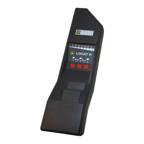
Le Récepteur Le Récepteur LOCAT R, modèle unique, est alimenté par une pile 9V. Il s'associe indifféremment à l'un des deux modèles d'Émetteur. Sensible au champ magnétique créé par le courant pulsé et à lui seul, le Récepteur réagit par l'émission d'un double signal sonore et visuel, proportionnel à l'intensité... -
Seite 8: Utilisation De L'émetteur
UTILISATION DE L'EMETTEUR ATTENTION : Avant de brancher l'Émetteur, toujours s'assurer que la tension du secteur est compatible avec la tension maxi indiquée sur l'émetteur : 140 V~ pour le LOCAT E 110 440 V~ pour le LOCAT E 220 Branchement En branchant l'Émetteur on sélectionne le circuit, le câble sur lequel on veut travailler. -
Seite 9: Montage Grande Boucle
Montage Grande Boucle Si l'Émetteur est directement branché dans une prise électrique, l'aller du courant pulsé se fait par l'un des câbles (phase) et le retour par l'autre (neutre). Dans ce cas les câbles conducteurs se trouvent en parallèle et les champs magnétiques émis sont égaux mais de sens contraires. -
Seite 10: Méthode De Pontage
Méthode du pontage Cette méthode du pontage est employée dans le cas du court-circuit phase/terre ou phase/neutre et permet de faire circuler le courant pulsé tout en maintenant le disjoncteur ouvert. On peut donc, avec l'Émetteur réaliser un pontage pour réalimenter une ligne en court-circuit (disjoncteur ouvert), par exemple pour un court-circuit phase/terre. -
Seite 11: Utilisation Du Récepteur
UTILISATION DU RECEPTEUR Après avoir raccordé l'Émetteur selon une des méthodes préconisées, adaptée au type de recherche, le courant pulsé va circuler dans un câble masqué à la vue (sous plinthe, encastré), ou visible, mais au milieu de dizaines d'autres, (dans une armoire). Avec le Récepteur il s'agit maintenant de suivre à... -
Seite 12: Méthode Du Maximum
Méthode du maximum Mise en oeuvre (voir schéma) : 1/ Partir de l'endroit où est branché l'Émetteur pour remonter vers la source de tension (voir A). 2/ Sélectionner la sensibilité Maxi et déplacer le Récepteur autour de l'Émetteur pour trouver la direction du câble (voir B et C). 3/ Procéder ainsi de suite en diminuant progressivement la sensibilité... -
Seite 13: Orientation Du Récepteur
NB: La méthode du maximum offre une précision d'autant meilleure que l'on peut approcher le Récepteur du câble recherché. On peut obtenir une précision meilleure que le centimètre. Cependant, si le câble est inaccessible (à 20 cm dans un mur par exemple), la localisation ne pourra se faire qu'à... -
Seite 14: Méthode Du Minimum
Méthode du minimum La méthode du minimum est utilisée lorsqu'on ne peut pas s'approcher suffisamment du circuit. Dans ce cas elle complète la méthode du maximum (voir ci-avant) pour obtenir une meilleure précision. Il faut pour cette méthode du minimum positionner le Récepteur parallè- lement au conducteur. -
Seite 15: Applications
APPLICATIONS Rappel : - toujours travailler entre l'Émetteur et la source de tension. - toujours éloigner l'aller du retour quand cela est possible (montage grande boucle) ATTENTION En triphasé, si la charge de l'une des phases est très capacitive, le courant pulsé à la fréquence de 3500 Hz peut dans certains cas traverser le condensateur équivalent de la charge et conti- nuer son parcours sur l'autre phase au lieu de revenir par le neutre. -
Seite 16: Suivi Et Identification D'un Conducteur
Suivi et identification d'un conducteur Il s'agit de suivre un conducteur tout au long de son parcours jusqu'à sa source et ceci même à travers des parois (jusqu'à 50 cm d'épaisseur). - Brancher l'Émetteur entre la phase de la prise dont on veut suivre le cheminement et une terre non adjacente au circuit de manière à... -
Seite 17: Court-Circuit Phase/Terre
Court-circuit phase/terre Dans le cas d'un défaut phase/terre suffisament important pour faire sauter les protections (disjoncteur différentiel), on utilise la méthode du pontage pour retrouver ce défaut. - Brancher l'Émetteur coté phase tel qu'indiqué sur le schéma. - Le courant circulera à travers le court-circuit et se refermera par la terre. - Présenter le Récepteur face au tableau des coupe-circuits ;... -
Seite 18: Court-Circuit Phase/Neutre
Court-circuit phase/neutre Même raisonnement que ci-dessus, mais cette fois le retour se faisant par le neutre, il faut court-circuiter le neutre comme indiqué sur le schéma. NB: Dans le cas d'un court-circuit phase/neutre il ne s'agit pas d'un montage grande boucle car le courant revient dans le même cable par le court-circuit. -
Seite 19: Court-Circuit Neutre/Terre
Court-circuit neutre/terre Dans le cas d'un court-circuit neutre/terre, on utilise la méthode du pontage pour retrouver ce défaut. - Brancher l'Émetteur comme indiqué sur le schéma. - Même raisonnement que court-circuit phase/terre. -
Seite 20: Repérage D'un Tuyau Bouché
Repérage d'un tuyau bouché NB : Le matériau de ce tuyau doit être non magnétique pour que le repérage soit possible. Cette méthode consiste à glisser un câble dans le tuyau jusqu'à l'endroit où il est bouché, cassé (dans un plancher, un sol...). 1ère solution Cette 1ère solution consiste à... - Seite 21 2ème solution Cette 2ème solution consiste à utiliser un cable blindé magnétiquement. D'un côté l'âme du câble est reliée à l'Émetteur et la tresse (en fer, acier) est reliée à la pile alimentant l'Émetteur. De l'autre côté, âme et tresse sont raccordées.
-
Seite 22: Pièges À Éviter
PIÈGES A ÉVITER Le LOCAT a la possibilité de détecter la présence d'une résistance de fuite phase/terre; cette résistance de fuite ne déclenchant pas nécessairement le disjoncteur différentiel. Attention donc aux erreurs d'interprétation ! Pour une installation sous 220 V, une résistance de fuite de 100 kW provoquera un courant de fuite de 2,2 mA (non détectable par le disjonc- teur différentiel). -
Seite 23: Caractéristiques Générales Et Conformité Aux Normes
CARACTÉRISTIQUES GÉNÉRALES ET CONFORMITÉ AUX NORMES COMPATIBILITÉ ÉLECTROMAGNÉTIQUE (selon NF EN 55 081 - 1 et NF EN 55 082 - 1) Émission : classe B (selon NF EN 55 014 et NF EN 55 022) Immunité - Décharges électrostatiques (selon CEI 801 - 2): Niveau 3 (8kV - aptitude B) - Champs électriques (selon CEI 801 - 3) : Niveau 2 (3 V/m - aptitude A) -
Seite 24: Maintenance
Fax : 02 31 64 51 09 RÉPARATION Réparation sous garantie et hors garantie. Adressez vos appareils à l’une des agences régionales MANUMESURE, agréées CHAUVIN ARNOUX Renseignements et coordonnées sur demande : Tél. : 02 31 64 51 43 Fax : 02 31 64 51 09 Réparation hors de France métropolitaine. -
Seite 25: Pour Commander
POUR COMMANDER Réf LOCAT 110 ..............P01.1416.21Z Ensemble complet comprenant : un Récepteur LOCAT R, un Emetteur E 110, un jeu de cordons n° 250B/249A (1), une pince crocodile verte, une pile 9 V alcaline et ce mode d'emploi. LOCAT 220 ..............P01.1416.22Z Ensemble complet comprenant : un Récepteur LOCAT R, un Emetteur E... - Seite 26 ENGLISH Meaning of the symbol Warning ! Please refer to the User’s Manual before using the instrument. In this User’s Manual, the instructions preceded by the above symbol, should they not be carried out as shown, can result in a physical accident or damage the instrument and the installations.
- Seite 27 SUMMARY Page PRINCIPLE ..................28 Notes on electromagnetism ............ 28 The Emitter ................28 The Receiver ................28 The advantages ..............28 PRESENTATION ................30 Unpacking the parts ............... 30 The Emitters LOCAT E 110 and E 220 ........30 The Receiver LOCAT R ............
-
Seite 28: Principle
PRINCIPLE Notes on electromagnetism An electrical current of intensity (i) passing through a conductor creates a magnetic field (H) surrounding this conductor throughout its length. The magnitude (H) of this magnetic field is proportional to the value of this current (i). A coil picking up this magnetic field (H) will therefore supply a strong signal if: - The current (i) is strong... - Seite 29 Princeple of the LOCAT EMITTER RECEIVER Voltage source THE EMITTER consumes a pulsed current (i): approx. 5 mA with frequency Fe = 3500 Hz (See p. 46) Specific magnetic field (H) with same frequency Fe THE RECEIVER signals the presence of this pulsed current. The signal is max.
-
Seite 30: Presentation
PRESENTATION Unpacking the parts RECEIVER The Emitter fits on to the Receiver. To separate them, simply slip a finger between the two elements. The Emitter is then easily extracted. To fit it back in again, insert it in its housing, pushing it well in until it clicks. -
Seite 31: The Receiver Locat R
The Receiver The Receiver LOCAT R, the only model of Receiver, is powered by a standard 9 V battery. It can be used with either of the two models of Emitter. Sensitive to the magnetic field created by the pulsed current, the Receiver reacts by the emission of a dual audio and visual signal, proportional to the intensity of the signal picked up and thus to the distance from the wire carrying the pulsed current. -
Seite 32: Using The Emitter
USING THE EMITTER WARNING: Before connecting the Emitter to the auxiliary power supply, always check that the network voltage is compatible with the maximum voltage indicated on the Emitter : 140 V AC for the LOCAT E 110 440 V AC for the LOCAT E 220 Connection When connecting the Emitter the user selects the circuit, the cable he wants to work on. - Seite 33 Connecting to a large loop If the Emitter is directly connected to an electrical socket, the outward pulsed current is carried by one of the wires (live) and the return by the other (neutral). In this case the conducting wires being in parallel the emitted magnetic fields are equal but in opposite directions.
-
Seite 34: Bridging Method
Bridging method Reminder : the Emitter is a load for the voltage circuit the same as any other. Because of its low consumption (I average < 5 mA) it doesn’t set- off upstream circuit breakers). This is the bridging method. A large loop connection can be easily connected in this way. -
Seite 35: Using The Receiver
USING THE RECEIVER After having connected the Emitter following one of the methods described, according to the type of trace to be done, the pulsed current will run in a cable which may be out of sight under skirting boards, in partitions,... or may be in a cupboard, but amongst tens of other wires. -
Seite 36: Method Of Maximum
Method of maximum Operation (see diagram) : 1/ Start from the point where the Emitter injection lead is connected (See A). 2/ Select max. sensitivity and move the Receiver around the Emitter to find the direction of the cable. (see B and C). 3/ Continue in this way progressively reducing the sensitivity until obtaining max. -
Seite 37: Pointing The Receiver
Pointing the Receiver NB : The position of the Receiver in relation to the cable carrying the pulsed current is important. It affects the detection. You will note when manipulating the Receiver, that when pivoting it by 90° through its longitudinal axis (line of sight) that the detection goes from Max. -
Seite 38: Method Of Minimum
Method of minimum The method of minimum is used when the circuit cannot be approached. In this case it completes the method of maximum (see above) to obtain greater accuracy. For this method of minimum, position the Receiver parallel to the conductor. Now move the Receiver one way or the other (see B and C) to find the minimum deviation of the visual display (see A). -
Seite 39: Applications
APPLICATIONS Reminder : - Always work between the emitter and the voltage source. - Always separate the outward and the return when possible (big loop connection). WARNING : In 3-phase, if the load on one of the phases is very capacitative, the pulsed current with a 3500 Hz frequency can in certain cases cross the condenser equivalent to the load and continue its run on the other phase instead of returning through the neutral. -
Seite 40: Following And Identifying A Circuit
Following and identifying a conductor How to follow a conductor throughout its run as far as its source even through walls (up to 50 cm thick). - Connect the Emitter between the live side of a socket which has a short circuit and a non-adjacent earth of the circuit so that a big loop is created. -
Seite 41: Live/Earth Short Circuit
Live/earth short circuit If the live/earth fault is sufficiently high to blow the protection (circuit breakers), the bridging method is used to find the fault. - Connect the Emitter to the live side as shown on the diagram. - The current crosses the short circuit and returns by the earth. - Hold the Receiver in front of the fuse board;... -
Seite 42: Live/Neutral Short Circuit
Live/Neutral short circuit The same reasoning as above, but this time the return is done through the neutral, the neutral return must be short circuited at the fuse board, as shown in the diagram. -
Seite 43: Neutral/Earth Short Circuit
In the case of a live/neutral short circuit it is not a big loop connection because the current comes back along the same cable to the short circuit. The signal therefore being quite weak, the probe must be placed quite close to the circuit so as to follow it to the point where it disappears at the short circuit. - Seite 44 1st solution This first solution consists of using a two wire lead connected to one side of the Emitter and to its battery power supply. On the other side the two wires are joined, making a loop. Along the lead, as the magnetic fields tend to cancel each other, the detection will be almost zero.
- Seite 45 2nd solution This second solution consists of using a magnetically screened cable. On one side the core of the cable is joined to the Emitter and the weave (iron, steel) is connected to the battery powering the Emitter. On the other side, core and weave are connected.
-
Seite 46: Traps To Avoid
TRAPS TO AVOID The LOCAT is able to detect the presence of a Live/Earth leak resistance: this leak resistance not necessarily setting off the circuit breaker. Care must be taken to avoid problems of interpretation! For an installation on 220V, a leak resistance of 100 kW will cause a leakage current of 2.2 mA (not detectable by the circuit breaker). -
Seite 47: General Specifications And Conformity With Standards
GENERAL SPECIFICATIONS AND CONFORMITY WITH STANDARDS ELECTROMAGNETIC COMPATIBILITY (To NF EN 55 081-1 and NF EN 55 082-1) Emission : class B (To NF EN 55 014 and NF EN 55 022) Immunity - Electrostatic discharges (To IEC 801-2) : level 3 (8kV - aptitude B) - Electric fields (To IEC 801-3) : level 2 (3V/m - aptitude A) - Rapid electrical transients (To IEC-4) : level 2 (1kV - aptitude B) EMITTERS LOCAT E110 and E220... -
Seite 48: Maintenance
CALIBRATION It is essential that all measuring instruments are regularly calibrated. For checking and calibration of your instrument, please contact our accredited laboratories (list on request) or the Chauvin Arnoux subsidiary or Agent in your country. REPAIRS Repairs under or out of guarantee: please return the product to your distributor. -
Seite 49: To Order
TO ORDER LOCAT 110 ................P01.1416.21Z Complete assembly comprising a LOCAT R Receiver, an E 110 Emitter, a set of leads n° 250B/249A , a green crocodile clip, a 9 V alcaline battery and this User’s Manual LOCAT 220 ................P01.1416.22Z Complete assembly comprising a LOCAT R Receiver, an E 220 Emitter, a set of leads n°250B/249A... -
Seite 50: Einleitung
DEUTSCH Bedeutung des Zeichens Achtung ! Beachten Sie vor Benutzung des Gerätes die Hinweise in der Bedienungs-anleitung. Falls die Anweisungen die in vorliegender Bedienungsanleitung nach diesem Zeichen erscheinen nicht beachtet bzw. nicht ausgeführt werden, können körperliche Verletzungen verursacht bzw. das Gerät und die Anlagen beschädigt werden. - Seite 51 INHALTSÜBERSICHT Seite FUNKTIONSPRINZIP .................. 52 - Elektromagnetische Grundlagen ............52 - LOCAT-Sender ..................52 - LOCAT-Empfänger ................. 52 - Die Vorteile ..................... 52 GERÄTEVORSTELLUNG ................54 - Trennen der Geräteteile ................. 54 - Die LOCAT-Sender E 110 und E 220 ............ 54 - Der LOCAT-Empfänger R ..............
-
Seite 52: Funktionsprinzip
FUNKTIONSPRINZIP Elektromagnetische Grundlagen Jeder in einem Leiter fließende elektrische Strom (i) erzeugt rund um den Leiter und auf dessen gesamterb Länge ein magnetisches Feld (H). Die Stärke (H) dieses magnetischen Feldes ist direkt zur Stromstärke (i) proportional. Eine Spule, die dieses Magnetfeld (H) empfängt, gibt ein Signal ab, das um so größer ist - je höher die Stromstärke (i) im Leiter ist, und/oder - je näher sich die Spule beim Leiter befindet. - Seite 53 FUNKTIONSPRINZIP LOCAT 220 SENDER EMPFÄNGER Spannungsquelle Der SENDER speist in den Leiter einen gepulsten Strom (i) von 5 mA mit der spezifischen Frequenz Fe = 3500 Hz ein (siehe S. 20). Erzeugtes Magnetfeld (H) mit derselben Frequenz Fe. Der EMPFÄNGER reagiert auf dieses Magnetfeld und zeigt dessen Stärke an: maximale Feldstärke in Position , geringere Feldstärken in Positionen...
-
Seite 54: Gerätevorstellung
GERÄTEVORSTELLUNG Trennen der Geräteteile EMPFÄNGER Der Sender läßt sich in den Empfänger einclip- sen. Zum Trennen der beiden Geräte einfach die Fingerspitze am Gehäuserand des Senders einschieben und Geräte auseinander drücken. Der Sender läßt sich nun bequem entnehmen. Zum Zusam-menfügen der beiden Geräteteile den Sender auf den Empfänger auflegen und SENDER fest einclipsen. -
Seite 55: Der Locat-Empfänger R
LOCAT-Empfänger Der LOCAT-Empfänger R ist für beide Sender identisch und wird durch eine eingebaute 9V-Blockbatterie mit Spannung versorgt. Empfängt er das typische von einem LOCAT-Sender erzeugte Magnetfeld, zeigt er dessen Feldstärke optisch und akustisch an. Die Stärke der Anzeige hängt direkt ab von der Nähe des Empfängers zum gesuchten Leiter. Symbol für akustisches Signal Die Stärke des Summtons ist direkt proportional zur Nähe des gesuchten Leiters. -
Seite 56: Benutzung Des Senders
BENUTZUNG DES SENDERS ACHTUNG: Vor Anschluß des Senders immer darauf achten, daß die jeweilige Anlagenspannung die maximal zulässige Spannung des LOCAT- Sendermodells nicht übersteigt: 140 V ~ beim LOCAT E 110 440 V ~ beim LOCAT E 220 Anschluß des Senders Vor Anschluß... -
Seite 57: Anschluß Mit Überbrückung
Anschluß mit “großer Stromschleife” Schließt man den Sender direkt an eine Steckdose an, so verläuft das gepulste Stromsignal zum einen über den Phasenleiter, gleichzeitig jedoch auch über den Nulleiter wieder zurück. Da diese beiden Leiter meist direkt nebeneinander verlegt sind, würden sich die Magnetfelder der beiden Kabel gegenseitig aufheben und der Empfänger könnte nur eine schwache Signalstärke feststellen. - Seite 58 Anschluß mit Überbrückung Zur Erinnerung: Der LOCAT-Sender ist für die Stromversorgung ein ganz normaler “Stromverbraucher”. Da er allerdings sehr wenig Strom aufnimmt (im Mittel weniger als 5 mA) lösen ein FI-Schutzschalter oder andere Sicherheitseinrichtungen nicht aus. Beim Anschluß mit Überbrückung wird im Falle von defekten Stromkreisen mit Kurzschlüssen zwischen Phase/Erde oder Phase/Nulleiter eine “große Stromschleife”...
-
Seite 59: Benutzung Des Empfängers
BENUTZUNG DES EMPFÄNGERS Nach Anschluß des LOCAT-Senders nach einem der obigen Schaubilder (je nachdem ob man ein Kabel identifizieren oder einen Defekt suchen will) fließt der gepulste Strom auf dem Leiter. Dieser Leiter kann unter Putz liegen, hinter Wänden verlaufen oder in einem Bündel anderer Kabel verborgen sein (z.B. in Kabelkanälen oder Schaltschränken). -
Seite 60: Maximum-Verfahren
Maximum-Methode Inbetriebnahme (siehe Abb.): 1) Dort beginnen, wo der Sender an den zu prüfenden Stromkreis angeschlossen ist und den Leiter bis zur Stromquelle zurückverfolgen (siehe A). 2) Maximale Empfindlichkeit einstellen (Taste “5”) und den Empfänger um den Sender bewegen bis die Abgangsrichtung des Kabels feststeht (siehe B, C). -
Seite 61: Ausrichtung Des Empfängers
Hinweis: Die Fehlersuche mit der “Maximum-Methode” ist um so präziser, je näher man mit dem Empfänger am gesuchten Leiter entlangfahren kann. Die erreichbare Genauigkeit liegt bei weniger als 1 cm. Ist der Leiter allerdings verborgen (z.B. 20 cm tief in einer Mauer verlegt) kann er auch nur auf ca. 20 cm genau lokalisiert werden. -
Seite 62: Minimum-Verfahren
Minimum-Methode Diese Methode wird sinnvollerweise dann angewandt, wenn man nicht sehr nahe an den Leiter herankommt. Als Ergänzung zum Maximum-Verfahren (siehe oben) läßt sich dann mit dem Minimum-Verfahren eine höhere Genauigkeit erreichen. Der Empfänger wird dazu parallel zum signalführenden Leiter ausgerichtet. Bei Bewegung nach rechts und links vom Leiter erhält man eine höhere Feldstärkeanzeige (siehe Positionen B und C in der Abb.) als wenn der Empfänger direkt über dem Leiter liegt (Position A) und die Spulenachse genau... -
Seite 63: Anwendungsbeispiele
ANWENDUNGSBEISPIELE Zur Erinnerung: - Der Suchbereich muß immer zwischen Stromversorgung der Anlage und Anschlußpunkt des LOCAT-Senders liegen. - Immer darauf achten, daß der Leiter zur Einspeisung des Signals getrennt von der Rückführung liegt (Anschluß mit großer Stromschleife). ACHTUNG Wenn in einer Phase eines Drehstromnetzes eine stark kapazitiv wirkende Last vorliegt, kann das vom LOCAT-Sender eingespeiste 3500 Hz-Signal unter Umständen über diese Kapazität in eine andere Phase übertragen werden, anstatt vollständig über den Nulleiter zurückzufließen. - Seite 64 Leitung auffinden und verfolgen Eine unter Putz oder bis zu 50 cm tief in einer Mauer verlegte Leitung soll gefunden und über ihre gesamte Länge verfolgt werden. - LOCAT-Sender an die Phase der Steckdose anschließen, deren Leitung verfolgt werden soll. Zweite Meßleitung an eine möglichst entfernte Erde anschließen (Anschluß...
-
Seite 65: Phase/Erde-Kurzschlub Suchen
Phase/Erde-Kurzschluß suchen Wenn ein Phase/Erde-Kurzschluß oder ein Fehlerstrom vorliegt, der z.B. die Sicherung oder den FI-Schutzschalter auslöst, läßt sich die Fehlerstelle durch Überbrücken des Trennschalters mit dem LOCAT-Sender leicht finden. - Mit dem LOCAT-Sender wie in der Abb. gezeigt den Phasen-Trennschalter überbrücken. -
Seite 66: Nulleiter/Erde-Kurzschlub Suchen
Phase/Nulleiter-Kurzschluß suchen Der Anschluß des LOCAT-Senders erfolgt wie oben. Da hier das Signal allerdings über den Nulleiter zurückfließt, muß der entsprechende Kontakt des Trennschalters ebenfalls überbrückt werden (siehe Abb.). Hinweis: Bei einem Kurzschluß Phase/Nulleiter läßt sich keine große Stromschleife realisieren, da der Strom über den meist parallel zur Phase verlegten Nulleiter zurückfließt. - Seite 67 Nulleiter/Erde-Kurzschluß suchen Wenn ein Nulleiter/Erde-Kurzschluß gesucht werden soll, benutzt man ebenfalls das Verfahren mit Überbrückung des Trennschalters. - Den LOCAT-Sender wie in der Abb. gezeigt anschließen. - Ansonsten verfährt man wie bei der Suche nach einem Phase/Erde-Kurzschluß (siehe oben).
-
Seite 68: Auffinden Von Rohrverstopfungen
Auffinden von Rohrverstopfungen Hinweis: Die Ortung der verstopften Stelle ist nur an Rohren aus nicht magnetischem Material möglich. Hierbei wird ein Kabel in das Rohr bis zu der Stelle eingeschoben, an der es verstopft ist. 1. Möglichkeit Bei diesem Verfahren wird eine Buchse des LOCAT E 110-Senders über eine externe 9 V-Batterie mit Spannung versorgt. - Seite 69 2. Möglichkeit Beim zweiten Verfahren wird ein geschirmtes Kabel, z.B. Koax-Antennenkabel, in das Rohr eingeschoben. Schirmung und Mittelleiter des Kabels werden an die 9 V-Batterie, bzw. den LOCAT E 110-Sender angeschlossen, am Kabelende ist die Schirmung mit dem Mittelleiter verbunden. Durch die Abschirmung heben sich die gegenläufigen Magnetfelder nicht auf und man kann den Verlauf des Rohres mit dem LOCAT-Empfänger gut verfolgen.
-
Seite 70: Problemfälle
PROBLEMFÄLLE Mit dem LOCAT-System können auch Fehlerströme zwischen Phase und Erde erkannt werden. Wenn ein solcher Fehlerstrom über einen hohen Widerstand abfließt, löst er den Fehlerstromschutzschalter nicht notwendigerweise aus. Allerdings sind Falschinterpretationen möglich! Bei einer 220 V-Elektroinstallation fließt über einen 100 kW -Widerstand ein Fehlerstrom von 2,2 mA, der vom FI-Schutzschalter nicht erkannt wird. -
Seite 71: Empfänger Locat R
ALLGEMEINE TECHNISCHE DATEN SENDER LOCAT E 110 und E 220 Stromversorgung - LOCAT E 110: von 9 V bis 140 V und ~ - LOCAT E 220 : von 180 V bis 300 V von 180 V bis 440 V ~ Der LOCAT-Sender E 110 läßt sich nicht nur durch das Netz, sondern auch mit einer externen 9V-Blockbatterie betreiben (die Anlage darf dabei nicht unter Spannung stehen!). -
Seite 72: Ersetzen Der Batterie
Niederlassung Ihres Landes. REPARATUREN Reparaturen während oder auberhalb des Garantiezeitraumes : senden Sie die Geräte zu Ihrem Wiederverkäufer. BESTELLANGABEN ..............LOCAT 110 1416.17Z Komplettsystem mit Empfänger LOCAT R, Sender E 110, Kabelsatz 208B/229 , 9V-Alkali-Batterie und Bedienungsanleitung ..............LOCAT 220 1416.15Z... - Seite 73 07-99 Code 906 120 319 - Ed. 3 Deutschland : CA GmbH - Strabburger Str. 34 - 77694 Kehl / Rhein - Tel : (07851) 99 26-0 - Fax : (07851) 99 26-0 España : CA Iberica - C/Roger de Flor N° 293 - 08025 Barcelona - Tel : (93) 459 08 11 - Fax : (93) 459 14 43 Italia : AMRA CA SpA - via Torricelli, 22 - 20035 Lissone (MI) - Tel : (039) 2 45 75 45 - Fax : (039) 48 15 61 Österreich : CA Ges.m.b.H - Slamastrasse 29 / 3 - 1230 Wien - Tel : (1) 61 61 9 61 - Fax : (1) 61 61 9 61 61 Schweiz : CA AG - Einsiedlerstrasse 535 - 8810 Horgen - Tel : (01) 727 75 55 - Fax : (01) 727 75 56...