Inhaltsverzeichnis

Verwandte Anleitungen für Wamsler W3-50


Inhaltszusammenfassung für Wamsler W3-50
- Seite 1 Aufstell- und Bedienungsanleitung Instructions for Installation and Use Instructions de montage et d’utilisation Istruzioni per l’installazione e l’uso Kezelési és beállítási útmutató W3-50...
-
Seite 2: Vorwort
Vorwort Sehr verehrter Kunde, Wir beglückwünschen Sie zum Erwerb unseres Festbrennstoffherdes. Sie haben die richtige Wahl getroffen. Denn mit diesem Produkte haben Sie die Garantie für Hohe Qualität durch Verwendung bester und bewährter Materialien. Funktionssicherheit durch ausgereifte Technik, die streng nach deutschen bzw. europäischen Normen geprüft ist. -
Seite 3: Inhaltsverzeichnis
Inhaltsverzeichnis Vorwort ........................... 2 Inhaltsverzeichnis ......................3 1. Installation ........................4 1.1 Sicherheitshinweise ....................4 1.2 Geräteaufbau ......................6 1.3 Vorschriften ......................8 1.4 Aufstellungsraum ..................... 8 1.5 Verbrennungsluft ..................... 9 1.6 Sicherheitsabstände ....................11 1.7 Schornsteinanschluss .................... 12 1.8 Wahl der Abgasanschlussrichtung ................ 12 1.8.1 Obenanschluss .................... -
Seite 4: Installation
1. Installation 1.1 Sicherheitshinweise 1. Die Geräte sind nach DIN EN 12815 geprüft (Typenschild). 2. Bei der Aufstellung und dem abgasseitigen Anschluss sind die anwendbaren nationalen und europäischen Normen, örtliche und baurechtliche Vorschriften/Normen (z.B. DIN 18896, DIN 4705, DIN EN 13384, DIN 18160, DIN EN 1856-2, DIN EN 15287 u.a.) sowie feuerpolizeiliche Bestimmungen (z.B. - Seite 5 22. Wenn Ausbesserungen oder Erneuerungen vorgenommen werden müssen, wenden Sie sich bitte rechtzeitig unter Angabe der genauen Art.Nr. und Fert.Nr. an Ihren Fachhändler. Es sind nur Original Wamsler - Ersatzteile zu verwenden. 23. Arbeiten, wie insbesondere Installation, Montage, Erstinbetriebnahme und Servicearbeiten sowie Reparaturen, dürfen nur durch einen ausgebildeten Fachbetrieb (Heizungs- oder...
-
Seite 6: Geräteaufbau
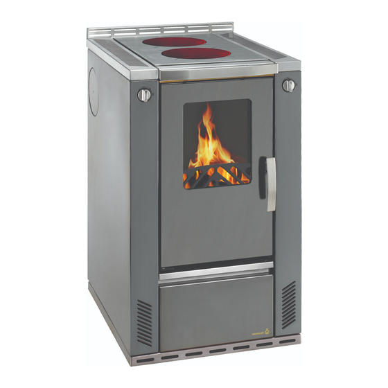
______________________________________________________________________ 1.2 Geräteaufbau W3-50 Legende Primärluftregler Kochplatte Abgasanschlüsse Anheizklappe Schamotteverkleidung im Feuerraum Rost Holzfang (Reling) Seitenwand Aschekasten 10. Sekundärluftregler 11. Brennstoffwagen 12. Sockelrahmen 13. Heiztür Serienzubehör Deckelheber Russkratzer Schürhacken Blinddeckelset Schutzhandschuh Sonderzubehör ISO Panel Anschlussset oben (nicht bei Voll-Ceranplatten möglich) Saugknopf (zu Glaskeramik Einsatz Hot Spots) Das Typschild befindet sich auf dem Brennstoffwagen Nr. - Seite 7 Demontage/Montage der W3-50 Sockel -Blende Demontage Sockelblende zuerst leicht (ca. 1cm) noch vorne ziehen Sockelblende hinten rechts und links aushängen und leicht nach außen ziehen (schlüsselförmige Öffnung „A”) Sockelblende nach vorne abnehmen Montage Sockelblende von vorne montieren Sockelblende hinten beidseitig leicht auseinander ziehen und den Bolzen in die Öffnung einhängen...
-
Seite 8: Vorschriften
Höhenverstellung: Sockelblende entfernen durch das herausnehmen des Brennstoffwagens, sind die höheverstellbaren Füße zugänglich Mit Hilfe eines Imbus-Schlüssels (Grösse 5) oder einem Gabelschlüssels (Grösse 17mm), kann der Herd auf die gewünschte Höhe/ ins Wasser nachgestellt werden Die passende Blende wird je nach Höhenbestellung (850 / 900 / 920 mm) mitgeliefert 1.3 Vorschriften Für die Aufstellung und dem abgasseitigen Anschluss sind die anwendbaren nationalen... -
Seite 9: Verbrennungsluft
Leistungsverhältnis von 4 m je kW Nennwärmeleistung gewährleistet ist. Ist das Volumen geringer, muss über Lüftungsöffnungen ein Verbrennungsluftverbund mit anderen Räumen hergestellt werden (Verbundöffnungen mind. 150 cm²). 1.5 Verbrennungsluft Für den Verbrennungsvorgang wird permanent Sauerstoff bzw. Luft benötigt. In der Regel reicht die vorhandene Luft im Aufstellraum aus. - Seite 10 Bitte beachten immer – Absprache Ihrem zuständigen Bezirksschornsteinfegermeister – die jeweils gültigen örtlichen Vorschriften und Regeln. Für Änderungen nach Drucklegung dieser Anleitung können wir keine Haftung übernehmen. Änderungen behalten wir uns vor. W3-50 Ansicht von unten Ansicht von der Seite...
-
Seite 11: Sicherheitsabstände
1.6 Sicherheitsabstände Die Sicherheitsabstände von brennbaren Gegenständen und von tragenden Wänden aus Stahlbeton, sowie Stellwänden die aus brennbaren Baustoffen hergestellt, oder mit brennbaren Baustoffen verkleidet sind einzuhalten: Unterhalb der Herdplatte (von Oberkante Herd bis Fußboden) A ≥ 800 mm B ≥ 3 mm* C ≥... -
Seite 12: Schornsteinanschluss
1.7 Schornsteinanschluss Der für den Anschluss vorgesehene Schornstein muss bis mind. 400 C belastbar sein. ACHTUNG: Anschluss Gerätes jedem Fall zuständige Bezirksschornsteinfegermeister / Bezirksbeauftragte zu Rate zu ziehen! Verbindungsstücke müssen am Gerät und untereinander fest und dicht verbunden sein. dürfen nicht freien Schornsteinquerschnitt... -
Seite 13: Seitenanschluss
1.8.2 Seitenanschluss hinteren Abgasstutzen (1) durch lockern der Schrauben entfernen Herdplatte (2) und Durchbrandplatten (3) heraus nehmen Sturzzugschale (4) vom Rauchgasweg heraus ziehen Abgasanschluss hinten mit Blinddeckel (5) von Außen verschließen und fest verschrauben Blinddeckel Innen (6) mit Blinddeckel Außen durch das Schraubenloch und der Schraube (7) verschrauben ... -
Seite 14: Maßnahmen Bei Schornsteinbrand
______________________________________________________________________ Richtig Falsch mind. 50 cm Querschnittverengung im Kamin durch zu weit eingeschobene Abgasrohre Stau durch sich ge- genseitig behin- mind. 30 cm dernde Abgasströ- Falschluft durch offene Türen an nicht benutzten Feuerstätten Falschluft durch of- fenen Rohranschluß Falschluft durch undichten Rohr- anschluß... -
Seite 15: Brennstoffe / Einstellungen
Nennwärmeleistung heizen. Sollte beim ersten Heizvorgang die max. Temperatur nicht erreicht werden, so können diese Erscheinungen auch später noch auftreten. Maximale Aufgabemengen pro Brennstofffüllung W3-50 3,1 kg (5 - 6 Briketts) bei Nennwärmeleistung Braunkohlebriketts und bei Dauerbrand (andere Einstellung, siehe Tabelle 2) -
Seite 16: Verbrennungslufteinstellung
2.2 Verbrennungslufteinstellung Die Einstellungen müssen immer in der Mitte der Bezeichnungen liegen. Sekundärluft Primärluft Anheizklappe Zeit Brennstoff Stellung Stellung Stellung ca. h Anheizen Scheitholz Braunkohlebriketts Braunkohlebriketts Dauerbrand Außerbetriebnahme keinen Brennstoff mehr nachlegen Tabelle 2 3. Bedienung 3.1 Bedienungselemente und Einstellungen 3.1.1 Primärluftregulierung Die Verbrennungsgeschwindigkeit und damit die Heizleistung des Herdes werden durch die unter dem Rost einströmende Verbrennungsluft bestimmt. -
Seite 17: Anheizklappe
3.1.3 Anheizklappe Zum Anzünden muss die Anheizklappe geöffnet und zum Kochen und Heizen geschlossen sein. Geschlossen (Kochen, Heizen) Offen ACHTUNG Eine offen stehende Anheizklappe während des Heizbetriebes führt zur Überhitzung des Herdes und damit zur Beschädigung von Herdteilen. Außerdem hat eine geöffnete Anheizklappe einen erhöhnten Brennstoffverbrauch zur Folge. 3.1.4 Aschekasten ... -
Seite 18: Anzünden
3.2 Anzünden Die Leistungsregulierung wird unter Beachtung der Brennstoffart je nach Zugstärke und gewünschter Heizleistung eingestellt. Mit Scheitholz insbesondere mit Weichholz, ist nur ein eingeschränkter Dauerbrand möglich. Braunkohlebriketts sind für den Dauerbrand über Nacht besonders geeignet, wenn sie auf eine satte Grundglut aufgelegt werden. Erstes Anheizen ... -
Seite 19: Kochen Und Heizen
3.3 Kochen und Heizen Wenn der Herd zum Kochen oder Heizen benutzt wird, ist die Anheizklappe zu schließen. Für ein optimales Kochen auf der Herdplatte empfiehlt es sich, nur Töpfe mit flachem Boden zu benützen. Die wärmste Zone befindet sich in der Mitte der Platte, die zugleich auch die beste Zone ist, um einen Topf rasch aufzuwärmen. -
Seite 20: Lackierte- Und Emailoberflächen
Mit richtigem Betrieb/Bedienung und guter Pflege/Wartung erhöhen Sie die Wertstabilität und Lebensdauer Ihres Gerätes. Sie sparen wertvollen Ressourcen und schonen unsere Umwelt und Ihren Geldbeutel. Zur Reinigung, ist die Herdplatte (2) abzunehmen, die Durchbrandplatten (3) und die Sturzzugschale (4) auszubauen und vom Russ zu befreien. -
Seite 21: Seitliches Schutzgitter
Stahlplatten neigen durch die Wärme (Feuer) mit der Zeit eine brünierte Farbe anzunehmen. Möchte man diesen allmählichen Prozess vorgreifen, braucht man nur die Platte häufig mit ein wenig säurefreiem Stahlplatten-Putzpflegemittel einreiben. Eine Verfärbung der Stahlplatten ist immer gegeben und liegt in der Natur des Stahles. Dies ist kein Grund für eine Reklamation. -
Seite 22: Störungsursachen, Behebung
3.7 Störungsursachen, Behebung Ihr Herd ist nach den neuesten technischen Erkenntnissen gebaut. Dennoch können Störungen auftreten, die meist ihre Ursache im Schornstein, im Brennstoff oder im Abgasrohrsystem haben. Eine kurzzeitige Geruchs- und Rauchentwicklung bei der ersten Inbetriebnahme ist normal. Auf eine ausreichende Belüftung des Raumes ist zu achten. -
Seite 23: Technische Daten
OGC (bezogen auf 13% O ≤ 120 mg/Nm NOx (bezogen auf 13% O ≤ 150 mg/Nm Wirkungsgrad ≥ 77 % 4.2 Maßzeichnungen W3-50 850 (+20) 695 (+20) 900 (+20) 745 (+20) 920 (+20) 765 (+20) Stellfüße herausschrauben, Herdhöhe von +20 mm möglich Die angeführten Abmessungsangaben sind nur zur Information! Wir behalten uns das Recht... -
Seite 24: Entsorgung Des Gerätes
Wamsler Haus- und Küchentechnik GmbH • Adalperostr. 86 • • D-85737 Ismaning • Tel. +49 (0)89 / 320 84-0 • Fax +49 (0)89 / 320 84-238 info@wamsler.eu • www.wamsler.eu © Wamsler Haus- und Küchentechnik GmbH, 85737 Ismaning. Alle Rechte und Änderungen vorbehalten. Stand 04.2020... -
Seite 25: Preface
Preface Dear Customer, Congratulations on your purchase of our solid fuel stove. You have made a good choice. Because this product guarantees you: High Quality by using proved materials with top quality. Safe function thanks to mature technology which has been tested for strict adherence to German and European standards. -
Seite 26: Inhaltsverzeichnis
Table of Contents Preface .......................... 25 Table of Contents ......................26 Installation ......................27 Safety measures ....................27 Parts ........................29 Instructions ......................30 Surrounding space .................... 31 Air supply ......................32 Safe distances....................34 Chimney attachment ..................35 Choice of flue gas connection placement ............35 1.8.1 Top connection (Fig. -
Seite 27: Installation
______________________________________________________________________ Installation Safety measures The stoves are tested to DIN EN 12815 (see identification plate). For installation and for flue gas connections, the requirements of the Fire Regulations (FeuVO in Germany) apply, as well as local building regulations such as the following technical standards DIN 4705, DIN EN 13384, DIN 18160, DIN EN 1856-2 and DIN EN 15287. - Seite 28 18. If repairs or replacements are necessary, please contact your supplier with the necessary article numbers and serial numbers in good time. Only original WAMSLER replacement parts may be used. 19. Work such as installation, setup, commissioning and services, as well as repairs, must only be carried out by qualified personnel (heating system or space heating technicians).
-
Seite 29: Parts
______________________________________________________________________ Parts W3-50 Key: Standard accessories: 1. Primary air control - Flue cover 2. Steel plate - Protective gloves 3. Flue gas connections - Lever to lift covers 4. Start damper - Soot scraper 5. Refractory clay layer in fire chamber - Fire iron 6. - Seite 30 ______________________________________________________________________ Disassembly / assembly of the W3-50 base cover Dismantling 1. First pull the plinth cover slightly (approx. 1 cm) in front 2. Unhook the base panel at the rear on the right and the left side and pull it slightly outwards (key-shaped opening "A")
-
Seite 31: Instructions
Height adjustment: 1. Remove the base cover 2. The height-adjustable feet are accessible by removing the fuel truck 3. With the help of an Allen key (size 5) or a fork key (size 17mm), the stove can be adjusted to the desired height / into the water 4. -
Seite 32: Air Supply
Air supply A constant supply of oxygen or air is required for the combustion process. Normally the air available in the room where the stove is installed will be sufficient. If the windows and doors are well insulated, if mechanical air extraction mechanisms are present ( e.g. - Seite 33 You must always comply – in consultation with the local authority responsible for approving heating systems – with the local rules and regulations. We cannot accept any responsibility for changes subsequent to the publication of this instruction manual. We reserve the right to make changes. W3-50 View from below Side view ______________________________________________________________________...
-
Seite 34: Safe Distances
______________________________________________________________________ Safe distances The following distances must be respected as safety margins from flammable objects and bearing walls made of reinforced concrete and partition walls made from flammable materials or covered in flammable materials: Beneath the hob plate (from the top of the stove to the floor) A ≥... -
Seite 35: Chimney Attachment
Chimney attachment The connection for attaching to the chimney must be able to withstand at least 400°C. PLEASE NOTE: Before connecting the stove the local authority responsible for approving heating systems must be consulted! Connection pieces must be firmly connected to the stove and to each other and must not leak. -
Seite 36: Side Connection (Fig. 1)
1.8.2 Side connection (Fig. 1) Remove the rear flue outlet (1) by loosening the screws. Remove the cooking plate (2) and the fire bricks (3) Remove the steel plate (4) in the exhaust Bolt tight the cover (6) at the inside with the outside cover (7). ... - Seite 37 Wrong Action in case of chimney fire! If a chimney is not cleaned often enough, or if the wrong type of fuel is used (e.g. damp wood) or the air flow is maladjusted the chimney may catch fire. In this case close the air supply to the fire chamber and call the fire brigade.
-
Seite 38: Fuels / Settings
Maximum fuel quantities per load W3-50 3.1 kg (5 - 6 briquettes) at nominal heat load Lignite briquettes 3.1 kg (5 - 6 briquettes) for long term load... -
Seite 39: Combustion Airflow Settings
Combustion airflow settings The settings must always be as shown. Primary Combustio Start damper Secondary Fuel airflow n duration setting airflow setting setting in hrs Lighting Nominal Firewood approx. 1 heat load Nominal Lignite briquettes approx. 2 heat load Long-term Lignite briquettes approx. -
Seite 40: Start Damper
3.1.3 Start damper For lighting the stove the start damper must be open and when cooking or heating it must be closed. 1 - Closed (cooking, heating) 2 - Open PLEASE NOTE: Leaving the start damper open when heating will cause the stove to overheat which will damage the stove and its parts. -
Seite 41: Cooking And Heating
the fire is burning strongly and there is a sufficient base of embers, add more fuel and shut the start damper off. The first time the stove is lit it should be done “gently”, with a small amount of fuel, to allow the stove parts to get used to the heat. -
Seite 42: Care And Cleaning
PLEASE NOTE: In the interests of clean air and safe functioning of the stove do not exceed the maximum quantities of fuel. Otherwise there is a risk of overheating, which can damage the stove. Damage of this kind is not covered by the guarantee. Reduced heating should only be achieved by reducing the quantity of fuel, never by reducing the primary airflow. -
Seite 43: Side Panel Top
remaining water to evaporate and so prevents rust forming. Take care that you do not use water to clean the stove when it is cold. Expansion joints in the steel hob plate must always be cleaned free of adhesions, to avoid deforming the steel hob plate and the side panels. -
Seite 44: Troubleshooting
Fig. 5 Troubleshooting Your stove has been built using modern technology. Even so, problems can arise, which may derive from the chimney, the fuel or the flue pipe system. There may briefly be smoke and an unpleasant smell the first time you use the stove: this is normal. -
Seite 45: Technical Data
Particles / dust (based on 13% O2) ≤ 40 mg/m³ CO ( based on 13% O2) ≤ 0,10 % Efficiency ≥ 77 % Dimensions W3-50 850 (+20) 695 (+20) 900 (+20) 745 (+20) 920 (+20) 765 (+20) screw feet can raise stove height by +20 mm... - Seite 46 Préface Cher client, Nous vous félicitons d’avoir fait l’acquisition de notre cuisinière à combustible solide. Vous avez fait le bon choix. Ce produit vous donne en effet la garantie d’une qualité élevée obtenue grâce à l’utilisation des matériaux les meilleurs et les mieux éprouvés, ...
- Seite 47 Sommaire 1. Installation ......................48 1.1 Consignes de sécurité ..................48 1.2 Structure de l’appareil ..................50 1.3 Règlements ...................... 51 1.4 Pièce d’emplacement ..................52 1.5 Air de combustion ..................... 53 1.6 Distances de sécurité ..................55 1.7 Raccordement à...
-
Seite 48: Installation
Installation Consignes de sécurité 1. Les appareils ont été contrôlés selon les normes DIN EN 12815 (Plaque signalétique). 2. Pour la mise en place des appareils et le raccordement aux cheminées d’évacuation des gaz, on devra observer les exigences énoncées par les directives concernant les appareils de chauffage (FeuFO en Allemagne) ainsi que les normes DIN 4705, DIN EN 13384, DIN 18160, DIN EN 1856-2 et DIN EN 15287. - Seite 49 à temps à votre commerçant spécialisé en lui indiquant exactement le numéro de référence et le numéro de fabrication. On ne peut utiliser que des pièces originales WAMSLER. 19. Les travaux, tels que, en particulier, l’installation, le montage, la première mise en service, les travaux de maintenance ainsi que les réparations ne pourront être...
-
Seite 50: Structure De L'appareil
______________________________________________________________________ Structure de l’appareil W3-50 Légende : Accessoires de série : Réglage de l’air primaire - Levier de couvercle Plaque d’acier - Brosse à suie Raccordement pour les gaz d’évacuation - Tisonnier Volet d’allumage - Gants de protection Revêtement réfractaire dans le foyer - Couvercle de sortie de fumée... - Seite 51 Démontage / montage du cache de fond W3-50 Démantèlement 1. Tirez d'abord le couvercle du socle légèrement (environ 1 cm) vers l'avant 2. Décrochez le panneau de base à l'arrière à droite et à gauche et tirez-le légèrement vers l'extérieur (ouverture en forme de clé "A") 3.
-
Seite 52: Règlements
Réglage de la hauteur: 1. Retirez le cache de fond 2. Les pieds réglables en hauteur sont accessibles en retirant le camion de carburant 3. À l'aide d'une clé Allen (taille 5) ou d'une clé à fourche (taille 17 mm), le poêle peut être réglé... -
Seite 53: Air De Combustion
Air de combustion De l’oxygène (de l’air) est nécessaire en permanence pour la combustion. Normalement l’air de la pièce où est placée la cuisinière suffit. L’alimentation en air peut être sérieusement perturbée si les portes et les fenêtres ferment hermétiquement, s’il existe des systèmes d’aspiration de l’air ambiant (par exemple dans la cuisine et la salle de bains), s’il existe d’autres foyers (aussi chauffe- eau et chauffage à... - Seite 54 – les directives et les lois en vigueur dans la région ou le pays où est installé la cuisinière. Nous déclinons toute responsabilité pour des changements intervenus après la date d’impression de ces instructions de service. Nous nous réservons le droit de procéder à des modifications. W3-50 Vue de l’arrière Vue de côté...
-
Seite 55: Distances De Sécurité
Distances de sécurité On devra respecter les distances de sécurité rapport à des objets inflammables aux murs portants en béton armé ainsi que par rapport aux parois en matériaux combustibles ou revêtues de matériaux combustibles : Au-dessous de la plaque de foyer (du bord supérieur de la plaque de foyer au plancher) A ≥... -
Seite 56: Raccordement À La Cheminée
Raccordement à la cheminée La cheminée prévue pour le branchement devra résister au minimum à une température de 400 °C. TTENTION Avant de raccorder l’appareil, il est nécessaire, dans tous les cas de consulter le ramoneur responsable de la circonscription ! Les éléments de la conduite d’évacuation doivent être bien fixés les uns aux autres. -
Seite 57: Choix De La Direction De L'évacuation Des Fumées
Choix de la direction de l’évacuation des fumées La buse d’évacuation des fumées est montée, en série, sur l’arrière de l’appareil. Si l’on choisit de raccorder la cuisinière à la cheminée par le haut ou par les côtés, l’orifice d’évacuation non utilisé devra être fermé. 1.8.1 Raccordement par le haut (figure 1) ... - Seite 58 Figure 1...
- Seite 59 Mesures à prendre dans le cas d'un feu de cheminée ! Lorsque la cheminée n'a pas été suffisamment nettoyée, ou lorsqu’on emploie un combustible inapproprié (du bois humide, par exemple) ou bien lorsque l’air de combustion est mal réglé, un feu de cheminée peu se déclarer. Dans un tel cas fermez l’air de combustion du foyer et appelez les pompiers.
-
Seite 60: Combustibles / Réglages
à l’avenir. Quantité maximale de combustible à ne pas dépasser lors du chargement W3-50 3,1 kg (5 - 6 briquettes de lignite) pour la puissance calorifique nominale. -
Seite 61: Réglage De L'air De Combustion
Réglage de l'air de combustion Les réglages doivent toujours être sur la position des marques placées sur l’appareil Position du Durée de Réglage de l’air Position de l’air Combustible volet combustion primaire secondaire d’allumage en heures Chauffer Bûches 1 env. Briquettes de 2 env. -
Seite 62: Volet D'allumage
3.1.3 Volet d’allumage Le volet d’allumage doit être ouvert pour l'allumage mais doit être fermé pendant le chauffage et la cuisson. Fermé (cuisson, cuire au four, rôtir, chauffer) Ouverte TTENTION Si le volet d’allumage reste constamment ouvert pendant le fonctionnement du chauffage, la cuisinière risque de surchauffer et des pièces peuvent être endommagées. -
Seite 63: Allumer
Allumer Tout d’abord, on réglera la puissance en tenant compte du type de combustible et de la puissance de chauffage souhaitée. Les bûches, et plus particulièrement le bois tendre ne permettent qu’un feu continu limité. Les briquettes de lignites sont particulièrement bien adaptées au feu continu nocturne si elles sont placées sur une bonne couche de braises. -
Seite 64: Mise Hors Service
La table de cuisson ne doit pas être surchauffée : une surchauffe ne présente pas d’avantages pour la cuisson et endommage la cuisinière. . Mise hors service Mettre le régulateur d’air primaire en position fermée (tableau 2) Laisser se consumer le reste de braise, laisser la cuisinière refroidir. Vider et nettoyer la chambre de combustion lorsque l'appareil est froid ! Consignes à... -
Seite 65: Surfaces Laquées Et Émaillées
fumée à l’intérieur de l’appareil de même que la buse d’évacuation des gaz de combustion. En ouvrant la de gaz résiduel plaque de fonte (4) il est possible de nettoyer la partie inférieure des conduits de fumée et le four. Une fois que les travaux de nettoyage sont achevés, les plaques intermédiaires et la plaque de cuisson devront être remises à... -
Seite 66: Inoxydable Caillebotis
Dessin en éclaté pour le chapitre 3.6 Soins et nettoyage : figure 4 3.6.5 Inoxydable caillebotis 1. inoxydable caillebotis en acier, de levage (Figure 5) 2. Tirer vers l'avant 3. levage et Après démontage de la grille en acier inoxydable, peut le plateau de trou sous-jacente, être nettoyé. -
Seite 67: Causes De Perturbations, Solutions
Causes de perturbations, solutions Votre cuisinière est construite selon l’état des techniques le plus récent en la matière. Toutefois, des perturbations peuvent être provoquées par la cheminée, le combustible ou le système de tuyaux d’évacuation de gaz. Des dégagements de fumées et d’odeurs sont normaux à... -
Seite 68: Caractéristiques Techniques
Poussière (pour 13% de O ≤ 40 mg/m³ CO (pour 13 % de O ≤ 0,10 % Rendement d'exploitation ≥ 77 % Dessins côtés W3-50 850 (+20) 695 (+20) 900 (+20) 745 (+20) 100 920 (+20) 765 (+20) Retirer les pieds réglables il est possible d’augmenter la hauteur de la cuisinière de 20mm. -
Seite 69: Premessa
Premessa Gentilissimo Cliente, ci complimentiamo con Lei per aver acquistato questa cucina a combustibile solido e per l’ottima scelta effettuata! Questo prodotto Le garantisce qualità elevata grazie all’utilizzo di ottimi materiali testati funzionamento sicuro grazie alle avanzate tecnologie rigorosamente testate secondo le norme tedesche ed europee ... -
Seite 70: Indice
Indice Premessa ........................69 Indice ......................... 70 Installazione ..................... 71 Avvertenze di sicurezza ................... 71 Struttura stufa ....................73 Normative ......................75 Luogo di installazione ..................75 Aria di combustione ..................76 Distanze di sicurezza ..................78 Distanze di sicurezza ..................78 Collegamento alla canna fumaria .............. -
Seite 71: Installazione
Installazione Avvertenze di sicurezza L’apparecchio e i suoi dispositivi sono stati testati sulla base della norma DIN EN 12815 (vedi targhetta di identificazione). Per l’installazione e il collegamento del lato gas sono da rispettare la norma per gli impianti di combustione (FeuVO per Germania), i regolamenti edilizi locali, nonché le norme DIN 4705, DIN EN 13384, DIN 18160, DIN EN 1856-2 e DIN EN 15287. - Seite 72 Tutti i componenti dovranno essere sostituiti esclusivamente con pezzi originali WAMSLER. 19. Eventuali lavori, in particolare l’installazione, il montaggio, la prima accensione, nonché i servizi di assistenza e di riparazione possono essere eseguiti solo da una ditta specializzata (in impianti di riscaldamento o riscaldamento ad aria).
-
Seite 73: Struttura Stufa
______________________________________________________________________ Struttura stufa W3-50 Legenda: Accessori di serie: Regolatore aria primaria - Apri - coperchio Piastra di acciaio - Raschiatore per fuliggine Raccordi scarico fumi - Attizzatoio Valvola di accensione - Guanto di protezione Rivestimento in refrattario nel focolare Griglia... - Seite 74 Montaggio della copertura W3-90: Smontaggio: Tirare avanti la copertura (circa 1 cm). Tirare la parte posteriore della copertura su due lati, rimuovendo la l’apertura della copertura dal fissaggio (apertura in forma di buco della serratura) Tirare avanti la copertura per rimuoverla dall’apparecchio. Montaggio: Riposare la copertura sull’apparecchio di fronte.
-
Seite 75: Normative
É possibile aumentare l’altezza dell’apparecchio da 850mm a 900mm o da 900mm a 920mm, come segue: Rimuovere la copertura dell’apparecchio come già abbiamo spiegato. Dopo aver smontato il cassetto, abbiamo accesso ai 4 piedi per regolare l’altezza. É possibile regolare i piedi con una chiave a brugola 5 o con una chiave a bocca 17 (c) fino all’altezza necessaria. -
Seite 76: Aria Di Combustione
Aria di combustione La combustione richiede sempre l’ingresso di aria e ossigeno. Solitamente è sufficiente l’aria presente nel locale di installazione. La presenza di finestre e porte chiuse ermeticamente, di ventilazioni meccaniche (ad es. in cucina o in bagno) o di altre stufe (anche caldaie a gas) nell’abitazione può disturbare in modo notevole la corretta alimentazione di aria. - Seite 77 (ca. 40 m³/h). Rispettare sempre, in accordo con il proprio tecnico specializzato, le norme e le regole locali vigenti. Non ci assumiamo nessuna responsabilità per eventuali modifiche successive alla messa in stampa. W3-50 Vista da sotto Vista dal lato...
-
Seite 78: Distanze Di Sicurezza
Distanze di sicurezza Si devono rispettare le seguenti distanze dagli oggetti infiammabili e dalle pareti portanti in cemento armato, nonché da tramezzi realizzati o rivestiti in materiali infiammabili: sotto la piastra di cottura (dallo spigolo superiore fino al pavimento) A ≥ 800 mm B ≥... -
Seite 79: Collegamento Alla Canna Fumaria
Collegamento alla canna fumaria La canna fumaria alla quale si è scelto di allacciare la stufa deve essere in grado di sopportare una temperatura minima di 400°C. ATTENZIONE: Prima di collegare l’apparecchio rivolgersi in ogni caso ad un tecnico specializzato! I tratti di collegamento della stufa devono essere ben saldati e sigillati. -
Seite 80: Attacco Laterale (Figura 1)
1.8.2 Attacco laterale (figura 1) Rimuovere il bocchettone uscita fumi posteriore (1) allentando le viti Togliere la piastra di cottura (2) e le pietre refrattarie (3). Togliere la piastra fumi (4). Chiudere dall´esterno l´attacco di scarico fumi sul retro mediante il coperchio cieco (5) e serrare a fondo le viti. - Seite 81 Come comportarsi in caso di incendio della canna fumaria Una pulizia non completa della canna fumaria, l’utilizzo di combustibile non idoneo (per esempio legna troppo umida) o l’impostazione sbagliata dell’aria della combustione potrebbero provocare un incendio della canna fumaria. In questo caso chiudere la presa d’aria della stufa e chiamare immediatamente i Vigili del Fuoco.
-
Seite 82: Combustibili / Impostazioni
Quantità massime per ricarica di combustibile W3-50 3,1 kg (5 - 6 mattonelle) alla potenza termica nominale Mattonelle di lignite 3,1 kg (5 - 6 mattonelle) con fuoco continuo (altra impostazione, v. -
Seite 83: Impostazione Aria Di Combustione
Impostazione aria di combustione La tabella mostra le impostazioni necessarie in base a tipo di funzionamento e combustibile. Aria secondaria Fuoco Valvola di Combustibile Aria primaria continuo accensione in h Riscaldamento Ceppi di legna ca. 1 Mattonelle di lignite PTN ca. -
Seite 84: Valvola Di Accensione
3.1.3 Valvola di accensione La valvola deve essere aperta per l’accensione e chiusa per il riscaldamento e la cottura. Chiusa (cuocere, cuocere al forno, riscaldare) Aperta ATTENZIONE: Se la valvola di accensione rimane aperta durante il riscaldamento, può essere provocato un surriscaldamento che danneggia i componenti della stufa. Inoltre, lasciare la valvola di accensione aperta comporta un elevato consumo di combustibile. -
Seite 85: Accensione
Accensione La regolazione della resa viene impostata tenendo conto del tipo di combustibile utilizzato in base al tiraggio e alla resa desiderata. Con i ceppi di legna, in particolare con la legna morbida, è possibile un funzionamento a fuoco continuo solo per un tempo limitato. Le mattonelle di lignite sono particolarmente idonee per un utilizzo notturno con fuoco continuo, se disposte su un abbondante letto di brace. -
Seite 86: Cucinare E Riscaldare
Cucinare e riscaldare Quando la cucina viene utilizzata per cucinare o riscaldare è necessario chiudere la valvola di accensione. Per una cottura ottimale si consiglia di utilizzare solo pentole con fondo piatto. La zona più calda, collocata al centro della piastra, è anche il punto migliore per scaldare velocemente le pentole. -
Seite 87: Manutenzione E Pulizia
Manutenzione e pulizia 3.6.1 Apparecchio (figura 4) Dopo aver aperto lo sportello e prima di ogni aggiunta di combustibile è necessario pulire la griglia mediante il raschiatore per fuliggine e l'attizzatoio. Il cassetto cenere (1) deve essere svuotato quotidianamente. Almeno una volta ogni tre giorni occorre eliminare le scorie dalla griglia. -
Seite 88: Piastra Di Acciaio
3.6.4 Piastra di acciaio I componenti della piastra devono essere frizionati con un detergente privo di acidi specifico per piastre in acciaio quando sono ancora tiepidi. La pulizia deve essere effettuata ad apparecchio freddo. Le speciali piastre in acciaio a diffusione di calore della cucina necessitano di una regolare manutenzione in seguito ad ogni cottura. -
Seite 89: Cause E Risoluzione Di Anomalie
Figura 5 Cause e risoluzione di anomalie Il Suo apparecchio è stato costruito in base a tecnologie d’avanguardia. Potrebbero tuttavia verificarsi delle anomalie legate alla canna fumaria, al combustibile o al sistema dei tubi di scarico. Con la prima accensione potrebbero essere emanati brevemente fumi e odori sgradevoli. -
Seite 90: Dati Tecnici
≤ 40 mg/m³ CO (in riferimento a un tenore O del 13%) ≤ 0,09 % Efficienza ≥ 77 % Disegno dimensionale W3-50 850 (+20) 695 (+20) 900 (+20) 745 (+20) 100 920 (+20) 765 (+20) Svitare i piedini, la stufa può essere alzata di 20 mm... -
Seite 91: Előszó
Előszó Tisztelt Ügyfelünk! Gratulálunk szilárd tüzelésű tűzhelyünk megvásárlásához. Ön jól választott, mert ezzel a termékkel garantáljuk a következőket: Kiváló minőség a legjobb és bevált alapanyagok alkalmazása révén Működésbiztonság a kifejlesztett technika révén, melyet német ill. európai szabványok szerint szigorúan ellenőrzünk. Hosszú... -
Seite 92: Tartalomjegyzék
Tartalomjegyzék Előszó ......................91 Tartalomjegyzék ....................92 1. Beszerelés ....................93 1.1 Biztonsági figyelmeztetések ..............93 1.2 Készülék felépítése ................. 95 1.3 Előírások ....................96 1.4 A beállítási tere ..................97 1.5 Égési levegő .................... 98 1.6 Biztonsági távolságok ................100 1.7 Kéménycsatlakozás ................ -
Seite 93: Beszerelés
1. Beszerelés 1.1 Biztonsági figyelmeztetések A készüléket a DIN EN 12815 szerint vizsgáltuk (típustábla). A beállításhoz és a füstgáz elvezetéséhez a tüzelési rendelet, a mindenkori országos építési rend, valamint a DIN 4705, DIN EN 13384, DIN 18160, DIN EN 1856-2 és a DIN EN 15287 követelményeit kell figyelembe venni. A készülék megfelelő... - Seite 94 18. Ha javítást vagy felújítást kell végezni, akkor a pontos cikkszám és gyártási szám megadása mellett időben forduljon a kereskedőhöz. Csak eredeti Wamsler-cserealkatrészeket szabad felhasználni. 19. Olyan munkákat, mint beszerelés, szerelés, első üzembe helyezés és szervízmunkák, valamint javításokat csak képzett szaküzem (fűtés vagy légfűtésszerelés) végezhet.
-
Seite 95: Készülék Felépítése
______________________________________________________________________ 1.2 Készülék felépítése W3-50 Magyarázat primer-levegő szabályozó főzőlap füstgáz-csatlakozók begyújtás segítő samottborítás a tűztérben rostély parázsfogó oldalburkolat hamuláda tüzelőanyag választó / Airlogic tüzelőanyag tároló fiók lábazat tüzelőajtó Szériatartozékok kezelőkulcs koromkaparó piszkavas vakfedél-készlet védőkesztyű Speciális tartozékok ISO panel felső csatlakozó készlet (teljes ceránlapnál nem lehetséges) szívógomb (hot-spot ceránbetétek kiemeléséhez) - Seite 96 W2 lábazat burkolat szerelése: Leszerelés: A burkolatot előre húzzuk (kb. 1 cm). A burkolatot két oldalt a hátsó részén széthúzzuk, kiakasztva a burkolat nyílását a rögzítőből.(kulcslyuk alakú nyílás) A burkolatot előre felé lehúzzuk a készülékről. Felszerelés: A burkolatot ráhúzzuk előlről a készülékre. Két oldalt széthúzva a burkolatot a hátsó...
-
Seite 97: Előírások
Lehetőség van a készülék magasságának növelésére 850-ről 900-ra vagy 920 mm-re, illetve 900-ról 920 mm-re az alábbiak szerint. Az előzőekben leírtak szerint eltávolítjuk a lábazat burkolatot. A fiók kiszerelése után válik hozzáférhetővé a 4db magasság állító láb, melyeket 5-ös imbusz kulcs vagy17-es villás kulcs ( C) segítségével tudjuk állítani, míg a tűzhely el nem éri a kívánt magasságot. -
Seite 98: Égési Levegő
1.5 Égési levegő Az égési folyamathoz folyamatosan oxigénre ill. levegőre van szükség. Rendszerint elegendő a beállítás terének levegője. Jól letömített ablakok és ajtók, a lakásban lévő mechanikus légtelenítők (pl. konyha vagy fürdő) vagy más tűzhelyek (gázkályhák is) a kifogástalan levegőellátást érzékenyen zavarhatják. - Seite 99 és beállítás terébe a szükséges égési levegőt (kb. 40 m /h) a tűzhelyhez pluszban odavezeti. 3. pont: Kérem, mindig vegye figyelembe – az illetékes területi kéményseprővel egyeztetve– a mindenkor érvényes helyi előírásokat és szabályokat. Jelen útmutató nyomtatása utáni változásokért felelősséget nem vállalunk. Fenntartjuk a változtatás jogát. W3-50 Alulnézet Oldalnézet...
-
Seite 100: Biztonsági Távolságok
1.6 Biztonsági távolságok Az éghető tárgyaktól, valamint acélbeton hordozó falaktól, éghető anyagokból gyártott vagy éghető anyagokkal burkolt falaktól való biztonsági távolságot be kell tartani: Tűzhely főzőlap alatt (főzőlap felső peremtől padlóig) A ≥ 800 mm B ≥ 3 mm* C ≥ 200 mm Tűzhely főzőlap felett (főzőlap sugárzási területe) A ≥... -
Seite 101: Kéménycsatlakozás
1.7 Kéménycsatlakozás A csatlakozásra szánt kémény legyen legalább 400 C-ig terhelhető. FIGYELEM: A készülék csatlakoztatása előtt minden esetben ki kell kérni az illetékes kéményseprő tanácsát! Az összekötő elemek egymás között és a készüléken legyenek szilárdan rögzítettek és tömítettek. Nem nyúlhatnak be a szabad kéménykeresztmetszetbe. A tűzhely és a kémény közötti összekötő... -
Seite 102: Oldalsó Csatlakozás
1.8.2 Oldalsó csatlakozás a hátsó füstgázcsonkot (1) a csavar meglazításával el kell távolítani a főzőlapot (2) és a hővédő lapokat (3) ki kell venni a füstterelőt (4) ki kell húzni a füstgázútból a füstgázcsonkot hátul a vakfedéllel (5) kívülről le kell zárni, és csavarral szorosan meg kell húzni ... - Seite 103 Intézkedések kéménytűz esetén! A kémény nem megfelelő tisztítása esetén, helytelen tüzelőanyag használatakor (pl. túl nedves fa) vagy hibás égési levegő beállítás esetén kéménytűz keletkezhet. Ebben az esetben zárja el az égési levegő az égető berendezésen, és hívja a tűzoltókat. Sose próbálja meg saját maga vízzel oltani. ________________________________________________________________________...
-
Seite 104: Tüzelőanyag / Beállítások
Ha az első fűtési folyamatnál a maximum hőmérsékletet nem érik el, akkor az erős szagképződés a későbbiekben még egyszer felléphet. Maximális rárakási mennyiség tüzelőanyag-töltésenként. W3-50 3,1 kg (5 - 6 brikett) névleges hőteljesítmény mellett Barnaszénbrikett és tartós tűznél (más beállítás, ld. 2. táblázat) Tűzifa... -
Seite 105: Kezelés
3. Kezelés 3.1 Kezelőelemek és beállítások 3.1.1 Teljesítményszabályozás Az égési levegő sebességét és ezzel a tűzhely hőteljesítményét a rostély alatt beáramló égési levegő határozza meg. Ezt a primer levegőt a teljesítményszabályozóval lehet beállítani. zárt tűzifa barnaszén 3.1.2 Tüzelőanyag választó / Airlogic A szekunder levegő... -
Seite 106: Hamuláda
3.1.4 Hamuláda A hamuláda a tűzhely alatt található. Rendszeresen ellenőrizni és üríteni kell. A hamuláda ürítését hideg készüléknél kell elvégezni. Legyen óvatos, mivel még parázs vagy égő fadarabok lehetnek benne. Kérem, figyeljen arra, hogy izzó égési maradványok ne kerüljenek a szemétbe. ... -
Seite 107: Főzés És Fűtés
FIGYELEM A fűtőajtó kinyitásakor helytelen kezelés vagy elégtelen kéményhuzat esetén füst szivároghat ki. Feltétlenül figyelni kell arra, hogy a fűtőajtót csak lassan, résnyire, majd pár másodperc múlva lehet teljesen kinyitni. Ezen kívül tüzelőanyag rárakásához a fűtőajtó kinyitása előtt már csak parázs lehet az égéstérben, azaz láng már ne legyen látható. -
Seite 108: Ápolás És Tisztítás
3.6 Ápolás és tisztítás 3.6.1 Készülék (4.kép) A fűtésajtó kinyitása után a rostélyt a koromkaparó és a piszkafa segítségével minden tüzelőanyagtól meg kell tisztítani. A hamuládát (1) naponta tisztítani kell. Legalább minden harmadik nap el kell távolítani a salakot a rostélyról. Helyes üzemeltetéssel / kezeléssel és megfelelő... -
Seite 109: Oldalsó Díszburkolatok
3.6.5 Oldalsó díszburkolatok 1. Burkolat első részének kiemelése. (5.kép) 2. Burkolat előretolása 3. Burkolat leemelése a helyéről. Felszerelés fordított sorrendben: 5. kép 3.6.1 ponthoz tartozó kép 4. kép ________________________________________________________________________... -
Seite 110: Zavart Előidéző Tényezők, Elhárítás
3.7 Zavart előidéző tényezők, elhárítás Az Ön tűzhelyét a legkorszerűbb műszaki ismeretek szerint gyártották. Ennek ellenére felléphet olyan zavar, melynek oka a kéményben, a tüzelőanyagban vagy a füstgázelvezető rendszerben található. Első üzembe helyezéskor rövid szag- és füstképződés normális. Ügyelni kell a helyiség megfelelő szellőztetésére. ZAVAR MEGOLDÁS A tűztér üvegablaka... -
Seite 111: Műszaki Adatok
Por (13% O -re vonatkoztatva) ≤ 40 mg/m³ CO (13% O -re vonatkoztatva) ≤ 0,10 % Hatásfok ≥ 77 % 4.2 Méretrajzok W3-50 850 (+20) 695 (+20) 900 (+20) 745 (+20) 920 (+20) 765 (+20) Lábakat kicsavarozni, tűzhely magassága +20 mm-rel állítható... - Seite 112 Wamsler Haus- und Küchentechnik GmbH • Adalperostraße 86 • D-85737 Ismaning • Tel. +49 (0)89 / 32084-0 • Fax +49 (0)89 / 320 84-238 info@wamsler.eu • www.wamsler.eu © Wamsler Haus- und Küchentechnik GmbH, 85737 Ismaning. Alle Rechte und Änderungen vorbehalten. Art. Nr.: 135480 Ausgabe 04/2020...