System Sensor ECO1003 Einbau- Und Wartungsanweisungen
ECO1003
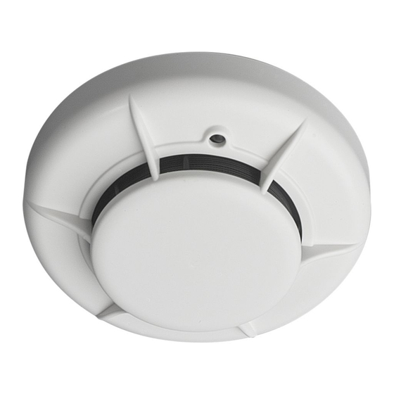
102 mm
75g
Fig. / Abb. 1
**
Fig. / Abb. 2a
V-
ECO1000B
ECO1000DB
ECO1000BRx
ECO1000DBRx
ECO1000BSD
ECO1000DBSD
ECO1000BRxSD
ECO1000DBRxSD
ECO1000(D)B,
ECO1000(D)BSD
V+
Fig. / Abb. 2b
ECO1000BRELx
V-
V+
INSTALLATION AND MAINTENANCE INSTRUCTIONS FOR
EN
ECO1003 PHOTO-ELECTRONIC SENSORS
SPECIFICATIONS
Supply Voltage:
8 - 30VDC
Quiescent current:
45µA Typical at 24VDC, 25°C
Maximum alarm current: 80mA (Limited by panel or base resistance)
Latching Alarm:
Reset by momentary power interruption.
IP Rating:
IP40 or IP43 with WB-1 (use WB-1 only with ECO1000DBx)
See ECO1003 Technical Data Sheet for further details
WARNING - Sensor characteristics may vary from other manufacturer products.
Check compatibility with panel supplier for any limitations. eg: maximum quantity
of devices per circuit.
BASE MOUNTING AND WIRING INSTRUCTIONS
See figures 2a or 2b for terminal connections. Sensor LED position marked by diode symbol
and arrow on base wall (*)
Notes: Do not loop wire under terminals: Break the wire run to ensure supervision of
connections.
All wiring must conform to applicable local and national codes and regulations.
Each ECO1000 base is fitted with a shorting spring to connect across terminals 1 and
2 to permit loop wiring to be checked before installation of sensor heads. This spring
automatically disengages when the sensor is fitted into the base.
WARNING - Remove power from sensor monitoring circuits before installing sensors.
SENSOR INSTALLATION
1. Place the sensor into the sensor base and rotate clockwise with gentle pressure until the
sensor drops into place. Continue rotating clockwise until the slot in the sensor cover
lines up with the lines moulded in the base (See fig 1 **).
D700-02-01
0832
0832 17
DoP Ref:
0832-CPD-0064
EN54-7
70 C
-30 C
60mm
50.8mm
V-
2
1
5
3
4
R
V+
ECO1000(D)BRx
ECO1000(D)BRxSD
V-
2
1
4
3
5
*
N/O
N/C
C
V+
3. After all sensors have been installed, apply power to the sensor monitoring circuits.
4. Test the sensor as described under TESTING.
17
Tamper-Resistance
The removal of the small plastic tab on the base indicated in figure 1 prevents the removal
of the sensor head without a tool.
CAUTION - Dust covers must be removed before the system can be made operational.
TESTING
Smoke Method
1. Using a test smoke from an approved manufacturer such as No Climb Products Ltd,
apply in accordance with the suppliers instructions
2. The red LED on the sensor should latch into alarm within 40 seconds, and the control
panel should activate into alarm.
Laser Test Tool Method (Model No. ECO1000RTU)
Note: This method does not carry out a complete functional test of the sensor.
1. Align the flashing red spot produced by the laser beam with the LED on the sensor.
2. Provided the sensor has not reached its drift compensation limit, it should latch into alarm
within a few seconds, and the control panel should activate into alarm.
MAINTENANCE
1. Remove the sensor to be cleaned from the system.
2. Gently release each of the cover removal tabs that secure the cover in place and remove
the sensor cover.
3. Vacuum the outside of the screen carefully without removing it.
4. Carefully remove the screen from the sensing chamber. Replacement screens are
available.
5. Use a vacuum cleaner and/or clean, compressed air to remove dust and debris from the
sensing chamber and the inside of the screen.
6. Re-install the screen by aligning the arrow moulded on it with the arrow on the sensing
chamber, sliding the screen over the chamber and applying gentle pressure to secure
it in place.
7. Reinstall the sensor cover. Align the LED with the cover assembly and snap the cover
into place, ensuring that all the cover removal tabs are correctly engaged.
8. When all the sensors have been cleaned, restore power to the circuit and test the sensor
as described in TESTING above.
WARNING - LIMITATIONS OF SMOKE SENSORS
Smoke sensors will only work when connected to a compatible control panel.
Smoke sensors have sensing limitations. They will not sense fires where smoke
does not reach the sensor, and different types of sensor will respond differently
*
to various smoke types.
Smoke sensors cannot last forever, and we recommended replacement after
10 years.
RIVELATORE FOTOELETTRONICO DI FUMO ECO1003
I
ISTRUZIONI DI INSTALLAZIONE E MANUTENZIONE
SPECIFICHE
Tensione di alimentazione:
Corrente di riposo:
Massima corrente d'allarme: 80mA (Limitata dalla centrale o dalla resistenza
Mantenimento allarme:
Valutazione del IP:
Maggior dettagli sono disponibili sul Data Sheet dei rivelatori ECO1003.
AVVERTENZA - le caratteristiche del rivelatore possono essere diverse da quelle
di altri prodotti del fornitore. Controlli la compatibilità con il fornitore del pannello
per ogni limitazione: per es. quantità massima di dispositivi per zona.
MONTAGGIO DELLA BASE ED ISTRUZIONI PER IL CABLAGGIO
edere figura 2a/2b per il collegamento dei terminali. La posizione che sarà assunta
dall'indicatore LED del rivelatore è segnalata dal simbolo del diodo e dalla freccia locati
sulla superficie interna della base di montaggio (*).
Note: Interrompere sempre il cablaggio per assicurare la supervisione delle connessioni.
Il cablaggio deve soddisfare le norme ed i regolamenti applicabili.
Ogni base ECO1000 è dotata di una molla di cortocircuito che può essere utilizzata per
collegare i terminali 1 e 2 permettendo così di verificare l'integrità del cablaggio prima
di procedere al montaggio dei rivelatori. Questa molla recupera la posizione di riposo
automaticamente all'innesto di un sensore.
ATTENZIONE - Togliere alimentazione ai dispositivi che controllano i rivelatori
prima di installarli.
INSTALLAZIONE DEL RIVELATORE
1. Posizionare il rivelatore nella base e ruotarlo in senso orario, esercitando una lieve
pressione, fino a quando il rivelatore non scivola in posizione. Continuare la rotazione
fino a che la fessura del rivelatore non risulta allineata al riferimento in rilievo della base
(vedere figura 1**).
2. Dopo aver installato tutti i rivelatori, dare l'alimentazione ai dispositivi che ne effettuano
il monitoraggio.
3. Verificare i sensori come descritto nel paragrafo TEST.
Anti-manomissione
La rimozione della piccola linguetta in plastica indicata in figura 1 rende necessario l'impiego
di un utensile per togliere il rivelatore dalla sua base.
CAUTELA - Le coperture parapolvere devono essere rimosse dai rivelatori prima
che il sistema sia reso operativo.
TEST
Risposta al fumo
1. Utilizzare un apparecchio di test della No Climb Products Ltd (od equivalente) secondo
le istruzioni fornite dal costruttore.
2. Il LED rosso sul sensore deve accendersi entro 40 secondi e la centrale di controllo deve
indicare la condizione di allarme.
Pittway Tecnologica Srl, Via Caboto 19/3, 34147 Trieste, Italy
8-30VCC
45µA tipico @ 24VDC, 25°C
presente nella base)
RESET mediante interruzione temporanea dell'alimentazione
IP40 o IP43 con WB-1 (WB-1 utilizzare solo ECO1000DBx)
I56-1653-022

Verwandte Anleitungen für System Sensor ECO1003


Inhaltszusammenfassung für System Sensor ECO1003
- Seite 1 Valutazione del IP: IP40 o IP43 con WB-1 (WB-1 utilizzare solo ECO1000DBx) Maggior dettagli sono disponibili sul Data Sheet dei rivelatori ECO1003. AVVERTENZA - le caratteristiche del rivelatore possono essere diverse da quelle di altri prodotti del fornitore. Controlli la compatibilità con il fornitore del pannello per ogni limitazione: per es.
- Seite 2 Uhrzeigersinn, bis er in die Aufnahme rutscht. Drehen Sie weiter, bis die Kerbe im Melder mit der Markierung im Sockel übereinstimmt (siehe Abb. 1**). Vea la Hoja de Características Técnicas de ECO1003 para posteriores detalles. 2. Wenn Sie alle Melder eingebaut haben, schalten Sie die Stromversorgung der ADVERTENCIA - Las características del detector pueden variar según el fabricante del...