effeff 720-20 Bedienungsanleitung
Inhaltsverzeichnis
Verfügbare Sprachen
Verfügbare Sprachen
®
deutsch
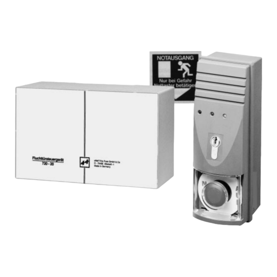
Fluchttürsteuergerät 720-20(22) /Türterminal 1337-10 (11)
english
Escape door control unit 720-20(22) /Door terminal 1337-10 (11)
Appareil de commande pour issues de secours 720-20(22) /
français
Terminal de porte 1337-10 (11)
D0007102
BEDIENUNGS-ANLEITUNG
OPERATING INSTRUCTIONS
NOTICE D'UTILISATION
SICHERHEIT
UND PRÄZISION
Inhaltsverzeichnis

Verwandte Anleitungen für effeff 720-20


Inhaltszusammenfassung für effeff 720-20
-
Seite 2: Inhaltsverzeichnis
○ ○ ○ ○ ○ ○ ○ ○ ○ ○ ○ ○ ○ ○ ○ ○ ○ Fluchttür Steuergerät 720-20 - technische Daten 16/17 ○ ○ ○ ○ ○ ○ ○ ○ ○ ○ ○ ○ ○ ○ ○ ○... - Seite 5 Ausführung dieser Schaltung unbedingt dem Stand der Technik entsprechen und Systemzusammenstellung größtmögliche Sicherheit bieten. mit Elektro-Fluchttüröffner – Fluchttürsteuergerät 720-20 Zu dieser Situation wurde im Hause effeff – Türterminal 1337-10/11 eine selbstüberwachende Sicherheits- – Türverriegelungselement schaltung entwickelt, die wie die Nottaste –...
-
Seite 6: Installation
Installationsrohren vorzunehmen. Nach ordnungsgemäßer Installation Installation kann die Inbetriebnahme erfol- Die fachmännische Installation der effeff- gen. Vor dem Einschalten ist die Span- Fluchttürsteuersysteme muß entspre- nungsversorgung von 230 V AC (24 V DC chend den „Bauaufsichtlichen Anforderun-... -
Seite 7: Gerätevorwahlschalter
(Kl. 42, 43 und 44) sowie der magneten bzw. durch einen Ankerkontakt optische Alarm (Kl. 8 u. Kl. 36) stehen im Paniköffner 3150 sowie im Flucht- weiter an. türöffner 331 RR AKRR geschaltet und an das Fluchttürsteuerungsgerät 720-20(22) zur Auswertung weitergeleitet. -
Seite 8: Funktionsschalter
Funktionsvorwahlschalter Kurzzeitfreigabe wird durch nach rechts Vorwahl: Türüberwachung Tasten des im Türterminal integrierten Funktionsschalter - S 4.1 Schlüsselschalters gesteuert (siehe Funk- tionszustand ”Kurzzeitfreigabe”). Bei offenem Türkontakt wird kein „Verrie- geln”-Befehl angenommen, außer wenn Bei Einstellung ”S 4.2 off” (unten) kann die der Dauerentriegelungskontakt (Kl 30) auf Kurzzeitfreigabe durch Tastimpuls auf die ”Verriegeln”... -
Seite 9: Direktanschluß Von Brandmeldern
– Zentralfreigabe (Kl 38) Anschluß einer externen Diese Einstellung kann bei einer ge- Brandmeldeanlage Kl 16/17 meinsamen Notentriegelung mehrerer Am Fluchttürsteuergerät 720-20(22) kann Fluchttüren eine mögliche Panik (evtl. der Auslösekontakt einer vorhandenen durch die akustischen Alarmmelder in Brandmeldeanlage (Ruhestromschleife) den Türterminal ausgelöst) verhindern. -
Seite 10: Funktionszustand / Steuereingang Dauerentriegelung
Übergang in Funktionszustand Mögliche Alarmkriterien: – Not-AUF-Schalter betätigt Entriegelung mit Alarm – Sabotagekontakt angesprochen Steuereingänge: – Zentralfreigabe aktiviert – Entriegeln aktiviert – Externe Brandmelderschleife hat = Entriegelungskriterium steht an, angesprochen Übergang in Funktionszustand – Zentrale Notentriegelung ist aktiviert – Dauerentriegelt –... -
Seite 11: Funktionszustand / Steuereingang Verriegelung
– Durch Entfernen des Jumpers J1 (im und solange der Steuereingang „Kurzzeit- Steuergerät) kann die Möglichkeit der freigabe“ aktiv ist, wird die Freigabezeit Dauerentriegelung am Schlüsselschalter nachgetriggert (nicht bei Steuereingang des Türterminals (Kl 3) abgeschaltet wer- „Verriegelung“). den. Dies bedeutet, daß durch Linksdre- Die Freigabezeit kann am Vorwahlschalter hung des Schlüsselschalters ausschließ- S1 zwischen 11 und 176 sec. -
Seite 12: Funktionszustand / Steuereingang Zeitgesteuerte Dauerfreigabe
Steuereingang “Kurzzeitfreigabe Steuereingang über Schalter“ ”Dauerfreigabe” (Kl. 28/TTL-Pegel gegen GND) (Kl. 30/TTL-Pegel gegen GND) Ein O-Signal an der Eingangsklemme lei- Solange ein O-Signal an der Eingangs- tet eine Kurzzeitfreigabe ein. Die über Vor- klemme ansteht, ist das System entriegelt. wahlschalter S 1 vorgegebene Freigabe- Öffnet der Ansteuerkontakt wieder (1-Si- zeit wird solange nachgetriggert wie das gnal an der Eingangsklemme), wird das... -
Seite 13: Funktionszustand Voralarm
Funktionszustand “Voralarm“ über. Funktionszustand “Entriegelung Meldet der Rückmeldekontakt der Tür vor mit Alarmmeldung“ Ablauf der Alarmunterdrückungszeit ”Tür Der Funktionszustand Notentriegelung geschlossen“, so wird das Verriegelungs- wird aktiviert, wenn z.B.: element bestromt, das System geht in den – der Not-Auf-Schalter im Türterminal Funktionszustand “Verriegelung“... -
Seite 14: Funktionszustand Verriegelung Mit Alarmmeldung
Funktionszusstand “Verriegelung auslösende Alarmmeldung weiter an, blinkt mit Alarmmeldung“ die Entriegelungsanzeige (grüne LED). Der Funktionszustand ”Verriegelung mit Die Parallelschaltung mit Steuereingang Alarm“ wird aktiviert, wenn im Funktions- ”Entriegeln“ über Jumper J1 bewirkt, daß zustand ” Verriegelt” der Rückmeldekontakt bei entsprechendem Funktionszustand des der Tür ”Tür offen“... -
Seite 15: Relaisausgang Hauptalarm
Relaisausgang “Hauptalarm“ Relaisausgang “Entriegelt/Verriegelt“ (Kl. 9/Relaisausgang, 24 V, (Kl. 18/19/20/Relaisausgang, Schaltstrom 1A max.). 24 V, Schaltstrom 1A max.) Ansteuerung der Signalhupe im Tür- Parallelausgang zum IC-Treiberausgang terminal oder eines externen Ansteuer- ”Verriegelt“. Das Relais ist angezogen, relais für eine Starktonhupe usw. Vorge- wenn das System verriegelt ist. - Seite 16 Sabotagekontakt Notauf-Türterminal Verriegelt-Rückmeldung Externe Brandmeldeanlage Zentral Not-Auf bei 720-22 oder Jumper J3 23/24 nicht bei 720-20 45/46 Melderschleife erfolgt keine Anzeige, dann liegt dieses Zentralfreigabe Alarmkriterium vor. Fluchttür-Steuergerät 720-20(22) Getaktetes Netzteil mit Schaltspannungs- regler 24 V und linearer Speicherdrossel.
-
Seite 17: Angaben Zur Belastung Durch Externe Geräte
Türterminal 1337-10 Einbaulage: waagerecht und (1337-11 mit uP-Rahmen) senkrecht für die Ansteuerung des Fluchttür- steuergerätes 720-20(22) Angaben zur Belastung durch externe Geräte: Das Türterminal 1337-10(11) ist ein Be- dien-und Überwachungsterminal, das vor Belastung durch angeschlossene Geräte Ort neben den Fluchttüren installiert wer- max. -
Seite 18: Türterminal 1337-10/11 Bedeutung Der Led-Anzeigen
LED's im Türterminal oder schalter im Türterminal). im Zentraltableau angezeigt. Dabei haben die einzelnen LED's folgende Bedeutung: Schlüsselschalter Funktion mit Flucht- Symbolik zu: türsteuergerät 720-20(22) und werks- seitiger Einstellung des DIP- Schalters LED rot LED grün LED gelb Grüne LED, Dauerlicht: System entriegelt. -
Seite 19: Türterminal 1337-10/11 - Technische Daten
Schlüsselschalter kurzzeitig The escape door control unit type durch Drehung des Schlüssels nach rechts 720-20(22) with integral power pack is de- betätigt werden. Ist der Funktionszustand signed for use with one door or two locking des Systems auf “Notentriegelung“ ge- elements. -
Seite 48: Verkabelungsplan 720
Verkabelungsplan 720-20 Zentraltableau 725 (bei Bedarf) Fluchttürsteuergerät 720.20 Siehe Anschlußplan 720.20-94-02/02 Netz 230 V +10% -14% Kurzzeitfreigabetaste Bei Bedarf: Notstromversorgung/ Fremdspannung 24 V= ± 15% Türkontakt Dauerfreigabe (Schalt- 14 Adern für Steuerleitungen uhr) Min. 2 Adern für Verriegelungselement (Spule) Achtung: Leitungsquerschnitt auslegen für max. 1V Spannungsabfall Brandmeldeanlage Türverriegelung w.w. -
Seite 51: Verkabelungsplan 720
Verkabelungsplan 720-22 Zentraltableau 725 (bei Bedarf) Fluchttürsteuergerät 720.22 Siehe Anschlußplan 720.22-94-02/01 Netz Kurzzeitfreigabetaste 230 V +10% -14% Bei Bedarf: Notstromversorgung/ Fremdspannung 24 V= ± 15% Türkontakt Dauerfreigabe (Schalt- 14 Adern für Steuerleitungen uhr) Min. 2 Adern für Verriegelungselement Achtung: Leitungsquerschnitt auslegen für max. 1V Spannungsabfall ! Brandmeldeanlage Türverriegelung w.w. - Seite 54 Freigabe- Alarmzeit Prozessor zeit Betriebssp. Vor- s. Bedienungsanl. Störung alarmzeit gelb Betriebsspan- nungsbereich: Ext. Brand- meldeanlage Türterminal 1337.10/11 Achtung! Auf richtigen Anschluß achten! Bei falschem Anschluß keine Garantieleistung. Die einschlägigen VDE-Vorschriften, sowie die Bestimmungen des örtlichen EVU sind zu beachten. Belastung der 24 VDC-Kleinspannung mit zusätzlichen externen Geräten siehe Belastungstabelle.
- Seite 55 Fluchttürsteuergerät 720-20 Bezeichnung der Betriebsspannungen: Achtung! 24,2 bis 26,5 VDC (Über Po 1 einstellbar) Brücke Jumper J3 Bezugspunkt für +UB muß gesteckt sein! +5 VDC (Elektronik und Prozessor) Bezugspunkt für VCC. und 0V sind getrennt geführt (EMV-Schutz) Zentraltableau 725..Bei Modellen 827 Funklöschdioden anschließen.
- Seite 60 Freigabe- Alarmzeit - Prozessor zeit Betriebssp. Vor- Störung s. Bedienungsanl. alarmzeit gelb Betriebsspan- nungsbereich: Ext. Brand- 198 - 253 VAC meldeanlage Türterminal 1337.30/31 Netz 230 V 50 Hz parallel zum Türterminal anschließbar Bedienteil 1332.10 Achtung! Auf richtigen Anschluß achten! Bei falschem Anschluß keine Garantieleistung. Die einschlägigen VDE-Vorschriften, sowie die Bestimmungen des örtlichen EVU sind zu beachten.
- Seite 61 Bezeichnung der Betriebsspannungen: Sicherheitssteuereinheit Fluchttürsteuergerät 720-22 +Ub 24,2 bis 26,5 VDC (Über Po 1 einstellbar) 720.22-92-02 Bezugspunkt für +UB VCC +5 VDC (Elektronik und Prozessor) Alarmrel. 4 Zentraltableau 725..Bei Modellen 827 Funklöschdioden anschließen. (Erhöhung der Störsicherheit) 2 x 828 / 1 x 829 331 RR AK RR 2 x 827 Paniköffner 3150...
-
Seite 69: Ersetzen Der Glühlampe Im Not-Auf-Schalter
Ersetzen der Glühlampe im NOT-AUF-Schalter Aufkleber- Schrauben Transparent- Oberteil ”NOT-AUF” lösen Kunststoffhaube abnehmen entfernen abnehmen Glühlampe herausnehmen und durch Arretierung des Glühlampe BA 9 s 24 - 30 V 1,2 W Schalterelementes lösen. bzw. Arretierungshebel in Stellung Glühlampe BA 9 s 12 - 15 V 1,2 W ”AUF”... -
Seite 72: Sicherheit Mit Zertifikat
Gemäß der im „Produkthaftungsgesetz” definierten Haftung des Herstellers für seine Produkte sind die im Gesamtkatalog enthaltenen Informationen (Produktinformationen und bestimmungsgemäße Ver- wendung, Fehlgebrauch, Produktleistung, Produktwartung, Informations- und Instruktionspflichten) zu beachten. Die Nichtbeachtung entbindet den Hersteller von seiner Haftungspflicht. ® effeff – Fritz Fuss GmbH & Co. Elektrotechnische Fabrik Elektro-Türöffner Postfach 490 Türsteuerungs-Systeme D 72425 Albstadt Telefon 074 31 .