Herunterladen Diese Seite drucken

Weidmuller WAVECONTROL VMR 1ph Beipackinformation

Spannungsüberwachungsmodul für ein- und dreiphasige netze

Werbung

Verfügbare Sprachen

Verfügbare Sprachen

WAVE
CONTROL
Spannungsüberwachungsmodul
für ein- und dreiphasige Netze
WAVE
CONTROL
Voltage - monitoring module
WAVE
CONTROL
Module de contrôle de tension
VMR 1ph / 3ph
VMR 1ph / 3ph
VMR
Beipackinformation
Operating instructions
Notice d'utilisation
\
4071410000/03/07.10
1
13
25

Werbung

loading

Inhaltszusammenfassung für Weidmuller WAVECONTROL VMR 1ph

  • Seite 1 Beipackinformation Operating instructions Notice d’utilisation WAVE VMR 1ph / 3ph CONTROL Spannungsüberwachungsmodul für ein- und dreiphasige Netze WAVE VMR 1ph / 3ph CONTROL Voltage - monitoring module WAVE CONTROL Module de contrôle de tension 4071410000/03/07.10...
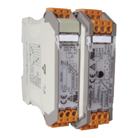
  • Seite 3 WAVE CONTROL Spannungsüberwachungsmodul Best.-Nr. Spannungsüberwachung 1-phasig WAS5 VMR 1ph 8705640000 Spannungsüberwachung 3-phasig WAS2 VMR 3ph 8705630000 Lesen Sie diese Beipackinformation bevor Sie das Produkt installieren und heben Sie diese für weitere Informationen auf.
  • Seite 4 Allgemeine Hinweise Achtung! Das Spannungsüberwachungsmodul der Reihe WAVE CONTROL darf nur von qualifizier tem Fachpersonal installiert werden. Erst nach der fachgerechten Installation darf das Gerät mit Hilfsener- gie versorgt werden. Während des Betriebs darf keine Be- reichsumschaltung vorgenommen werden, da hierbei berüh- rungsgefähr liche Teile offen liegen.
  • Seite 5 ein Relais mit Wechselkontakt realisiert. Das Gerät arbeitet grundsätzlich im Ruhestromverfahren, d.h. das Relais ist im Status OK angezogen und fällt bei einer Alarmmeldung ab. Der Schaltpunkt wird mit einem Potentiometer eingestellt (unter der Kunststofffrontscheibe angebracht). Funktionen: - High Trip: Relais schaltet bei Überschreitung der ein- gestellten Schaltschwelle - Low Trip:...
  • Seite 6 Spannungsüberwachungsmodul WAS2 VMR 3ph Das Modul überwacht 1- und 3-phasige Spannungen von 80Vac/dc bis 400Vac/dc. Die Spannungsversorgung erfolgt über den Überwachungseingang. Die Schaltausgänge sind über Re- lais mit Wechselkontakt realisiert. Die Schaltpunkthysterese ist fest (5%) auf den Messbereichsendwert eingestellt. Die 3 Phasen werden über LED’s (frontseitig sichtbar) separat angezeigt.
  • Seite 7 Konfigurierung des Gerätes Hilfsmittel Zum Einstellen des Gerätes und zum Anschluss der Leitungen an die Klemmen wird ein Schraubendreher mit einer Klingenbrei- te von 2,5 mm benötigt. Gerät öffnen Stecker abziehen. Durch leichten Druck den Verschluss auf beiden Seiten des Gehäuses entriegeln , Gehäuseoberteil und Elektro- nik herausziehen...
  • Seite 8: Einstellungen

    Einstellungen 3.3.1 Tabelle der Einstellmöglichkeiten für WAS5 VMR 1ph Eingang 24Vac/dc...70Vac/dc 70Vac/dc...140Vac/dc 140Vac/dc...210Vac/dc 210Vac/dc...260Vac/dc Trip High Trip Low Trip Speicher Memory ein Memory aus Hysterese Hysterese klein Hysterese gross Eingangsspannung AC-Spannung DC-Spannung...
  • Seite 9 3.3.2 Tabelle der Einstellmöglichkeiten für WAS2 VMR 3ph Eingang 3 Phasen 80Vac/dc...250Vac/dc 1 Phasen 200Vac/dc...400Vac/dc Grenzwert Einstellung auf oberen Schaltpunkt Einstellung auf unteren Schaltpunkt Hysterese Hysterese klein Hysterese gross Ausfallsicherheit Arbeitsstromverfahren Ruhestromverfahren...
  • Seite 10 Einstellbeispiele Einphasige Unterspannungsüberwachung mit WAS5 VMR 1ph keine Unterschreitung der Sollwertes Alarmzustand Alarmzustand lässt sich zurücksetzen, da Sollwert überschritten wurde Alarmauslösung mit Einstellung Low Trip (Ruhestromprinzip fest eingestellt) 100% Schaltschw elle Hysterese Zeit Relais/Low Trip Memory aus Relais/Low Trip Memory ein Reset für Ausgang min.
  • Seite 11 Dreiphasige Über- und Unterspannungüberwachung mit WAS2 VMR 3ph Einstellbeispiel: Hysterese 5% = -12,5V - Dreiphasenüberwachung - Das Gerät arbeitet im Arbeits- - Einstellung des Grenzwertes mit stromprinzip Potentialwerte auf obere Schalt- - Alle 3 Phasen werden parallel schwelle: 230V überwacht Hysterese 5% = -12,5V Statusanzeige - Untere Schaltschwelle 10%...
  • Seite 12 Der elektrische Anschluss WAS5 VMR 1ph WAS2 VMR 3ph Klemme Klemme 1 + Reset (18Vdc...30Vdc) 1 1 Eingang L1 (200Vac/dc…400Vac/dc) 2 nc 2 nc 3 – Reset 3 Eingang L1 (80Vac/dc…250Vac/dc) 4 nc 4 Eingang L2 (80Vac/dc…250Vac/dc) 5 Eingang (24Vac/dc...260Vac/dc) 5 Eingang N 6 Eingang (24Vac/dc...260Vac/dc) 6 Eingang L3 (80Vac/dc…250Vac/dc)
  • Seite 13 Abmessungen in mm 92,4 17,5 mm Baubreite WAS VMR 1ph 22,5 mm Baubreite WAS VMR 3ph...
  • Seite 14 Zubehör Verbindermarkierer Bezeichnung Best.-Nr. WS 10/5 Multicard für Plotterbeschriftung 1635010000 WS 10/5 Neutral 1060860000 Hinweise zur CE-Kennzeichnung Das Spannungsüberwachungsmodul VMA Vac trägt das CE-Zeichen und erfüllt die Anforderungen der EU-Richtlinien 2004/108/EG "Elektro mag ne tis c h e Verträglichkeit" und 2006/95/EG (Niederspannungsrichtlinie).
  • Seite 15 WAVE CONTROL Voltage-monitoring module Type Order. No. Voltage monitoring, single-phase WAS5 VMR 1ph 8705640000 Voltage monitoring, three-phase WAS2 VMR 3ph 8705630000 Before you install the product, please read the information contained in these operating instructions carefully and keep for future reference.
  • Seite 16 General notes Warning ! Voltage-monitoring modules from the WAVE range CONTROL should be installed by qualified staff only. Auxiliary power should only be supplied after the device has been correctly in- stalled. Do not alter the range when in operation, because this exposes live parts with dangerous contact voltages.
  • Seite 17 The switching point is set via a potentiometer (located under the front plastic cover). Functions: - High Trip: The relay switches when the set operating point is exceeded - Low Trip: The relay switches by underflow of the set operating point - Memory on: The output alarm status is retained;...
  • Seite 18 Voltage-monitoring module WAS2 VMR 3ph The module monitors single- and three-phase voltages from 80Vac/dc to 400Vac/dc. Power is supplied via the monitoring in- put. Relays with changeover contacts are used for the switch- ing outputs. The operating point hysteresis is non-adjustably set (5%) according to the upper limit of the effective range.
  • Seite 19 Configuring the module Required tool A screwdriver with a 2.5-mm blade is required to set the module and to connect the conductors to the terminals. To open the module Remove the connector. Disen- gage the locking mechanism by lightly pressing the locks on both sides of the housing , remove the upper part of the housing...
  • Seite 20 Settings 3.3.1 Table of settings options for WAS5 VMR 1ph Input 24Vac/dc...70Vac/dc 70Vac/dc...140Vac/dc 140Vac/dc...210Vac/dc 210Vac/dc...260Vac/dc Trip High Trip Low Trip Memory Memory on Memory off Hysteresis Hysteresis, small Hysteresis, large Input voltage AC voltage DC voltage...
  • Seite 21 3.3.2 Table of settings options for WAS2 VMR 3ph Input Three phase 80Vac/dc...250Vac/dc Single phase 200Vac/dc...400Vac/dc Limit value Setting at the upper operating point Setting at the lower operating point Hysteresis Hysteresis, small Hysteresis, large Fault tolerance Working current method Closed-circuit current method...
  • Seite 22 Settings examples Monitoring single-phase undervoltage with WAS5 VMR 1ph No underflow of the setpoint value Alarm status The alarm status can be reset, because set- point value was exceeded Alarm trip with setting Low Trip (Closed-circuit current principle permanently set) 100% Operating point Hysteresis...
  • Seite 23 Monitoring 3-phase over- and undervoltage with WAS2 VMR 3ph Settings example: - Three-phase monitoring Hysteresis 5% = -12.5 V - Setting the limit value with poten- - The module works on the tial values on the upper operating worikng current principle point: 230 V - All 3 phases monitored parallel Hysteresis 5% = -12.5V...
  • Seite 24 Electrical connection WAS5 VMR 1ph WAS2 VMR 3ph Terminal Terminal 1 + reset (18 Vdc...30 Vdc) 1 1 input L1 (200Vac/dc…400 Vac/dc) 2 nc 2 nc 3 – reset 3 Input L1 (80Vac/dc…250 Vac/dc) 4 nc 4 Input L2 (80Vac/dc…250 Vac/dc) 5 Input (24Vac/dc...260Vac/dc) 5 Input N 6 Input (24Vac/dc...260Vac/dc)
  • Seite 25 Dimensions in mm 92.4 Cross-connections power supply 24 Vdc WAS VMR 1ph: 17.5 mm wide WAS VMR 3ph: 22.5 mm wide...
  • Seite 26 Accessories Connection markers Designation Cat. No. WS 10/5 Multicard for plotter marking 1635010000 WS 10/5 Neutral 1060860000 Notes concering the CE Mark The voltage monitoring module carries the CE mark, and fulfils the requirements of the EU Directives 2004/108/EC “Electro- magnetic Compatibility”...
  • Seite 27 WAVE CONTROL Module de contrôle de tension Type Réf. Contrôle de tension monophasé WAS5 VMR 1ph 8705640000 Contrôle de tension triphasé WAS2 VMR 3ph 8705630000 Veuillez lire la notice jointe avant d'installer le produit et conservez-là pour consultation ultérieure.
  • Seite 28 Remarques générales Attention! Le module de contrôle de tension de la gamme WAVE CONTROL ne doit être installé que par un personnel qualifié. L'équipement ne doit être alimenté en énergie auxiliaire qu'après installation dans les règles de l'art. Ne pas tenter de changer de plage pen- dant le fonctionnement, des pièces dangereuses par contact di- rect sont en effet accessibles.
  • Seite 29 rant de repos, c.-à-d. que le relais est excité à l'état OK et re- tombe sur message d'alarme. Le point de commutation se règle à l'aide d'un potentiomètre (situé sous la face avant en plas- tique). Fonctions : - Déclenchement haut : Le relais commute sur dépassement du seuil réglé...
  • Seite 30 Module de contrôle de tension WAS2 VMR 3ph Ce module surveille les tensions monophasées et triphasées de 80Vca/cc à 400Vca/cc. L'alimentation en tension s'effectue par l'entrée contrôle. Les sorties commutées sont réalisées par relais à contact inverseur. L'hystérésis de commutation est réglé en fixe (5%) sur la valeur de pleine échelle.
  • Seite 31 Configuration de l'appareil Outillage Pour régler l'appareil et raccorder les conducteurs sur les bor- nes , il faut un tournevis plat de largeur 2,5 mm. Ouverture de l'appareil Débrancher le connecteur mâle. En appuyant légèrement, déver- rouiller le loquet des deux côtés , sortir la partie supérieure du boîtier et l'électronique...
  • Seite 32 Réglages 3.3.1 Tableau des réglages possibles du WAS5 VMR 1ph Entrée 24Vca/cc...70Vca/cc 70Vca/cc...140Vca/cc 140Vca/cc...210Vca/cc 210Vca/cc...260Vca/cc Déclenchement Déclenchement haut Déclenchement bas Mémoire Mémoire activée Mémoire désactivée Hystérésis Petite hystérésis Grande hystérésis Tension d'entrée Tension CA Tension CC...
  • Seite 33 3.3.2 Tableau des réglages possibles du WAS2 VMR 3ph Entrée 3 phases 80Vca/cc à 250Vca/cc 1 phase 200Vca/cc à 400Vca/cc Seuil Réglage au seuil supérieur Réglage au seuil inférieur Hystérésis Petite hystérésis Grande hystérésis Sécurité en cas de panne Sécurité négative (courant de travail) Sécurité...
  • Seite 34 Exemples de réglage Contrôle de manque tension monophasée avec le WAS5 VMR 1ph pas de soupassement de la consigne Etat d'alarme AL'alarme peut être réinitialisée car la consigne a été dépassée Déclenchement d'alarme par réglage du déclenchement bas (Sécurité positive fixée) 100% Seuil de commutation Hystérésis...
  • Seite 35 Contrôle de surtension et de manque tension triphasée avec le WAS2 VMR 3ph Exemple de réglage : Hystérésis 5 % = -12,5 V - Contrôle de tension triphasée - L'appareil fonctionne en sécurité - Réglage du seuil à des valeurs de négative potentiel au seuil de commutation - Les 3 phases sont surveillées en...
  • Seite 36 Raccordement électrique WAS5 VMR 1ph WAS2 VMR 3ph Borne Borne 1 + Réinit. (18Vcc à 30Vcc) 1 1 entrée L1 (200Vca/cc à 400Vca/cc) 2 nc 2 nc 3 – Réinit 3 entrée L1 (80Vca/cc à 250Vca/cc) 4 nc 4 entrée L2 (80Vca/cc à 250Vca/cc) 5 Entrée (24Vca/cc à...
  • Seite 37 Dimensions en mm 92,4 Connexion transversale d’alimentation en tension 24 Vdc Largeur 17.5 mm WAS VMR 1ph Largeur 22.5 mm WAS VMR 3ph...
  • Seite 38 Accessoires Repères de blocs de jonction Désignation Réf. WS 10/5 Multicarte pour libellés de table traçante 1635010000 WS 10/5 Neutre 1060860000 Remarques relatives au marquage CE Le module de contrôle de tension VMA Vac porte le marquage CE et remplit les exigences des directives de l'union européenne 2004/108/CE "Compatibilité...

Diese Anleitung auch für:

Wavecontrol vmr 3ph