Monacor TVCCD-119 Kurzanleitung
®
D
A
CH
S/W-Türspionkamera
1 Einsatzmöglichkeiten
Die Schwarzweißkamera mit einem extremen Weit-
winkelobjektiv ist für den Einsatz als Türspion in
Videoüberwachungsanlagen (CCTV) konzipiert. Sie
kann in Türen mit einer Stärke von 42 mm bis 66 mm
eingebaut werden. Die Kamera verfügt über einen
automatischen elektronischen Shutter und eine auto-
matische Verstärkungsregelung (AGC).
2 Hinweise für den sicheren Gebrauch
Die Kamera entspricht der EU-Richtlinie für elektro-
magnetische Verträglichkeit 89/336/EWG.
Schützen Sie die Kamera vor Tropf- und Spritz-
wasser, hoher Luftfeuchtigkeit und extremen Tem-
peraturen (zulässiger Einsatztemperaturbereich
0 – 40 °C).
Berühren Sie die Objektivlinsen nicht mit den Fin-
gern und verwenden Sie für ihre Reinigung nur Mit-
tel speziell für optische Linsen.
Wird die Kamera zweckentfremdet, nicht richtig mon-
tiert, falsch angeschlossen oder nicht fachgerecht
repariert, kann keine Haftung für daraus resultieren-
de Sach- oder Personenschäden und keine Garantie
für die Kamera übernommen werden.
B/W Spyhole Camera
GB
1 Applications
The black-and-white camera with an extra wide angle
lens is designed for use as a spyhole camera in video
surveillance systems (CCTV). It can be installed in
doors of a thickness from 42 mm to 66 mm. The cam-
era has an automatic electronic shutter and an auto-
matic gain control (AGC).
2 Safety Notes
The camera corresponds to the directive for electro-
magnetic compatibility 89/336/EEC.
Protect the camera against dripping water and
splash water, high air humidity, and extreme tem-
peratures (admissible ambient temperature range
0 – 40 °C).
Do not touch the lenses of the lens assembly with
your fingers and only use specific cleaning agents
for optical lenses for cleaning.
No guarantee claims for the camera and no liability
for any resulting personal damage or material
damage will be accepted if the camera is used for
other purposes than originally intended, if it is not
correctly mounted, connected, or not repaired in an
expert way.
1
12 V
2
Video
®
Copyright
TVCCD-119
Soll die Kamera endgültig aus dem
Betrieb genommen werden, übergeben
Sie sie zur umweltfreundlichen Entsor-
gung einem örtlichen Recyclingbetrieb.
3 Inbetriebnahme
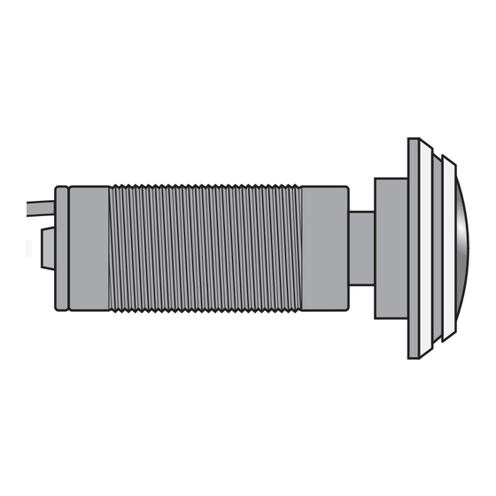
1) Ein Loch mit einem Durchmesser von 21 mm in die
Tür bohren. Zusätzlich eine Aussparung für die
Verlegung des Kabels fräsen.
2) Die Kamera, z. B. wie in der Abbildung gezeigt, an
der Tür montieren. Dabei die Montagehülse (4)
über die Kamera (6) schrauben, so dass die Tür (5)
dazwischen klemmt. Das Kabel in die seitliche Nut
des Flansches der Montagehülse legen. Die Mon-
tagehülse erst nach einem Testbetrieb mit der Tür
verschrauben.
3) Das Videosignal am BNC-Stecker (2) über ein ab-
geschirmtes Kabel auf den Videoeingang eines
Monitors geben. Bei einer Kabellänge über 100 m
sollte ein Videoverstärker zwischen Kamera und
Kabel geschaltet werden, um die Kabelverluste aus-
zugleichen.
4) An die Kleinspannungskupplung (1) ein stabilisier-
tes 12-V-Netzgerät mit einer Belastbarkeit von
mindestens 110 mA anschließen (z. B. PS-362ST
oder PS-500ST von MONACOR). Es wird ein
Kleinspannungsstecker 5,5/2,1 mm (Außen-/In-
nendurchmesser) benötigt. Unbedingt auf die rich-
If the camera is to be put out of operation
definitively, take it to a local recycling plant
for a disposal which is not harmful to the
environment.
3 Operation
1) Drill a hole with a diameter of 21 mm into the door.
In addition, mill a cutout for laying the cable.
2) Mount the camera to the door, as shown in the
figure. Screw the mounting sleeve (4) over the
camera (6) so that the door (5) is clamped inbe-
tween. Lay the cable in the lateral groove of the
mounting sleeve flange. Perform a test operation
before screwing the mounting sleeve to the door.
3) Feed the video signal at the BNC plug (2) via a
screened cable to the video input of a monitor. With
a cable length of more than 100 m, it is recom-
mended to insert a video amplifier between the
camera and the cable to compensate cable loss.
4) Connect a regulated 12 V power supply unit with a
power rating of at least 110 mA (e. g. PS-362ST or
PS-500ST from MONACOR) to the low-voltage
inline jack (1). A low voltage plug 5.5/2.1 mm (out-
side/inside diameter) is required. Observe in any
case the correct polarity: Place the positive pole at
the centre contact of the plug.
©
by MONACOR INTERNATIONAL GmbH & Co. KG, Bremen, Germany. All rights reserved.
Best.-Nr. 19.0280
4
3
tige Polung achten: Den Pluspol an den Mittelkon-
takt des Steckers anlegen.
5) Nach dem Anlegen der Betriebsspannung den
Monitor einschalten und die Kamera so drehen,
dass das Bild richtig herum auf dem Monitor
erscheint. Erst jetzt die Montagehülse (4) an der
Tür festschrauben. Die Abdeckkappe (3) auf den
Flansch der Montagehülse schrauben; dabei dar-
auf achten, dass das Kabel in der seitlichen Nut
des Flansches liegt.
4 Technische Daten
Bildaufnehmer: . . . . . . . CCD-Chip, 8,5 mm (
Video-System: . . . . . . . CCIR, hor. 15 625 Hz, vert.
50 Hz
Anzahl der Bildpunkte: . hor. 500 x vert. 582
Auflösung: . . . . . . . . . . 400 Linien
Objektiv: . . . . . . . . . . . . 1 : 1,2/1,78 mm
Shutter: . . . . . . . . . . . .
1
/
s bis
50
Mindestbeleuchtung: . . 0,01 Lux
Gamma-Korrekturfaktor: 0,45
Signal/Rausch-Abstand: > 45 dB
Videoausgang: . . . . . . . 1 Vss / 75 Ω
Einsatztemperatur: . . . . 0 – 40 °C
Stromversorgung: . . . . . 12 V /110 mA
Änderungen vorbehalten.
5) After applying the operating voltage, switch on the
monitor and turn the camera so that the picture
appears on the monitor in the correct way before
screwing the mounting sleeve (4) to the door.
Screw the cover (3) on the mounting sleeve flange;
pay attention that the cable is placed in the lateral
groove of the flange.
4 Specifications
Image sensor: . . . . . . . 8.5 mm (
Video system: . . . . . . . . CCIR, hor. 15 625 Hz,
vert. 50 Hz
Number of pixels: . . . . . hor. 500 x vert. 582
Resolution: . . . . . . . . . . 400 lines
Lens: . . . . . . . . . . . . . . 1 : 1.2/1.78 mm
Shutter: . . . . . . . . . . . .
1
/
s bis
50
Minimum illumination: . . 0.01 lux
Gamma correction
factor: . . . . . . . . . . . . . . 0.45
S/N ratio: . . . . . . . . . . . > 45 dB
Video output: . . . . . . . . 1 Vpp/75 Ω
Ambient temperature: . . 0 – 40 °C
Power supply: . . . . . . . 12 V /110 mA
Subject to technical modification.
5
min. 42 mm
max. 66 mm
A-0380.99.01.02.2005
®
1
/
")
3
1
/
s
100 000
1
/
") CCD chip
3
1
/
s
100 000
6

Verwandte Anleitungen für Monacor TVCCD-119


Inhaltszusammenfassung für Monacor TVCCD-119
- Seite 1 Place the positive pole at expert way. the centre contact of the plug. Subject to technical modification. 12 V min. 42 mm max. 66 mm Video ® Copyright © by MONACOR INTERNATIONAL GmbH & Co. KG, Bremen, Germany. All rights reserved. A-0380.99.01.02.2005...
- Seite 2 Con riserva di modifiche tecniche. 12 V min. 42 mm max. 66 mm Video ® Copyright © by MONACOR INTERNATIONAL GmbH & Co. KG, Bremen, Germany. All rights reserved. A-0380.99.01.02.2005...
- Seite 3 Należy dopilnować, żeby kabel znajdował się w środowiska. rowku kołnierza tulei. Może ulec zmianie. 12 V min. 42 mm max. 66 mm Video ® Copyright © by MONACOR INTERNATIONAL GmbH & Co. KG, Bremen, Germany. All rights reserved. A-0380.99.01.02.2005...