Monacor TW-220SET Bedienungsanleitung
Aktive videosignalübertragungseinheit
®
D
A
CH
Aktive Videosignal-
Übertragungseinheit
Bitte lesen Sie diese Anleitung vor dem Betrieb gründlich
durch und heben Sie sie für ein späteres Nachlesen auf.
1 Verwendungsmöglichkeiten
Das TW-220SET dient zur Übertragung von Videosigna-
len über lange, verdrillte Leitungen. Das Set besteht aus
einem Sender und einem Empfänger, die zum Betrieb
jeweils eine Spannung von 12 V benötigen.
Das Set ist für folgende Kabellängen geeignet:
100 – 1500 m bei Farbsignalen
100 – 2400 m bei S/W-Signalen
Für Kabel unter 100 m ist das Set nicht geeignet. Die Ver-
stärkung ist für kurze Kabel zu hoch, sodass Signalver-
zerrungen entstehen.
2 Wichtige Hinweise für den Gebrauch
Die Übertragungseinheit entspricht allen erforderlichen
Richtlinien der EU und ist deshalb mit
G
Die Übertragungseinheit ist nur zur Verwendung im
Innenbereich geeignet. Schützen Sie sie vor Tropf- und
Spritzwasser, hoher Luftfeuchtigkeit und Hitze (zulässi-
ger Einsatztemperaturbereich 0 – 40 °C).
G
Verwenden Sie zum Reinigen nur ein trockenes, wei-
ches Tuch, niemals Wasser oder Chemikalien.
G
Wird die Übertragungseinheit zweckentfremdet, nicht
richtig installiert oder falsch bedient, kann keine Haftung
für daraus resultierende Sach- oder Personenschäden
Active Video Signal
GB
Transmission Unit
Please read these operating instructions carefully prior to
operating the unit and keep them for later reference.
1 Applications
The TW-220SET serves for transmitting video signals via
long, twisted cables. The set consists of a transmitter and a
receiver which each require a voltage of 12 V for operation.
The set is suitable for the following cable lengths:
100 to 1500 m for colour signals
100 to 2400 m for B/W signals
The set is not suitable for cables shorter than 100 m. The
amplification is too high for short cables so that signal dis-
tortions occur.
2 Important Notes
The transmission unit corresponds to all required direc-
tives of the EU and is therefore marked with
G
The transmission unit is suitable for indoor use only.
Protect it against dripping water and splash water, high
air humidity, and heat (admissible ambient temperature
range 0 – 40 °C).
G
For cleaning only use a dry, soft cloth, never use chem-
icals or water.
G
No guarantee claims for the transmission unit and no
liability for any resulting personal damage or material
damage will be accepted if the transmission unit is used
for other purposes than originally intended, if it is not
correctly installed or operated.
POWER
®
CCD CAMERA
VIDEO IN
Kamera
Camera
®
Copyright
TW-220SET
und keine Garantie für die Übertragungseinheit über-
nommen werden.
Soll die Übertragungseinheit endgültig aus dem
Betrieb genommen werden, übergeben Sie sie
zur umweltgerechten Entsorgung einem örtlichen
Re cyclingbetrieb.
3 Anschluss
1) Den Sender und den Empfänger an geeigneter Stelle
festschrauben. Montagematerial für jedes Teil liegt bei.
2) Den Sender und den Empfänger jeweils über den An -
schluss
3) Die Signalverbindungen nach der Abbildung unten her-
stellen. Dort ist ein Beispiel mit einer Überwachungs -
kamera und einem Monitor dargestellt.
4) Die Adern des Übertragungskabels sollten verdrillt sein,
um eine hohe Störfestigkeit zu erreichen. Treten trotz-
dem Einstrahlstörungen auf, ein abgeschirmtes, verdrill-
tes Kabel verwenden.
5) Je weils ein stabilisiertes 12-V-Netzgerät (z. B. PS-300ST
gekennzeichnet.
von MONACOR) an die Kontakte DC IN des Senders
und Empfängers an schließen.
Wichtig! Der Sender und der Empfänger dürfen nicht
vom gleichen Netzgerät versorgt werden. Durch die
zusätzliche Verbindung über das Netzgerät entstehen
sonst Signalverzerrungen.
If the transmission unit is to be put out of opera-
tion definitively, take it to a local recycling plant for
a disposal which is not harmful to the environ-
ment.
3 Connection
1) Tightly screw the transmitter and the receiver at a suit-
able place. Mounting material is supplied for each part.
2) Ground the transmitter and the receiver via the con-
nection
3) Make the signal connections according to the figure
below. An example of a surveillance camera and a
monitor is shown.
4) The cores of the transmission cable should be twisted
to reach a high resistance to interference. If radiating
interference should occur in spite of this, use a
screened, twisted cable.
5) Connect a regulated 12 V power supply unit each (e. g.
.
PS-300ST from MONACOR) to the contacts DC IN of
the transmitter and the receiver.
Important! The transmitter and the receiver must not
be supplied by the same power supply unit. Otherwise
signal distortions occur due to the additional connection
via the power supply unit.
4 Adjustment
1) In case of negative picture display on the monitor,
exchange the two cores of the transmission cable at the
transmitter or the receiver.
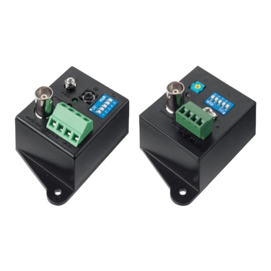
Sender
Transmitter
VIDEO OUT DC IN
Übertragungskabel, min. 100 m, max. 2400 m
+ –
Transmission cable, 100 m min., 2400 m max.
12 V
©
by MONACOR INTERNATIONAL GmbH & Co. KG, Bremen, Germany. All rights reserved.
Best.-Nr. 18.1570
erden.
in each case.
Empfänger
Receiver
4 Abgleich
1) Wird das Bild auf dem Monitor negativ dargestellt, die
beiden Adern des Übertragungskabels am Sender oder
am Empfänger vertauschen.
2) Jeweils am Sender und am Empfänger die DIP-Schal-
ter auf die Länge des Übertragungskabels einstellen:
100 – 300 m
nur DIP-Schalter Nr. 1 auf ON
300 – 600 m
nur DIP-Schalter Nr. 2 auf ON
600 – 900 m
nur DIP-Schalter Nr. 3 auf ON
900 – 1200 m
nur DIP-Schalter Nr. 4 auf ON
> 1200 m
nur DIP-Schalter Nr. 5 auf ON
3) Am Empfänger den Regler
auf Rechtsanschlag stellen
(min. Verstärkung). Am Sender mit dem Regler
optimale Bildwiedergabe (Kontrast) einstellen. Ist bei
Linksanschlag die Bildwiedergabe noch nicht optimal, mit
dem Regler
am Empfänger die Verstärkung erhöhen.
5 Technische Daten
Sender
Videoeingang: . . . . . . . . . . 1 Vss/75 Ω, BNC
Frequenzbereich: . . . . . . . bis 5 MHz
Stromversorgung: . . . . . . . 12 V /40 mA
Maße, Gewicht: . . . . . . . . . 42 × 46 × 72 mm, 58 g
Empfänger
Videoausgang: . . . . . . . . . 1 Vss/75 Ω, BNC
Frequenzbereich: . . . . . . . 50 Hz – 10 MHz
Stromversorgung: . . . . . . . 12 V /40 mA
Maße, Gewicht: . . . . . . . . . 42 × 46 × 72 mm, 56 g
Änderungen vorbehalten.
2) Adjust the DIP switches at the transmitter and the
receiver to the length of the transmission cable:
100 – 300 m
only DIP switch No. 1 set to ON
300 – 600 m
only DIP switch No. 2 set to ON
600 – 900 m
only DIP switch No. 3 set to ON
900 – 1200 m
only DIP switch No. 4 set to ON
> 1200 m
only DIP switch No. 5 set to ON
3) Set the control
at the receiver to the right stop (mini-
mum amplification). Adjust an optimum picture display
(contrast) with the control
at the transmitter. If the pic-
ture display is not yet optimum with the control at the left
stop, increase the amplification with the control
receiver.
5 Specifications
Transmitter
Video input: . . . . . . . . . . . . 1 Vpp/75 Ω, BNC
Frequency range: . . . . . . . up to 5 MHz
Power supply: . . . . . . . . . . 12 V /40 mA
Dimensions, weight: . . . . . 42 × 46 × 72 mm, 58 g
Receiver
Video output: . . . . . . . . . . . 1 Vpp/75 Ω, BNC
Frequency range: . . . . . . . 50 Hz – 10 MHz
Power supply: . . . . . . . . . . 12 V /40 mA
Dimensions, weight: . . . . . 42 × 46 × 72 mm, 56 g
Subject to technical modification.
VIDEO
POWER
VIDEO OUT
VIDEO IN DC IN
– +
12V
Monitor
H-HOLD
V-HOLD
BRIGHT
A-0853.99.01.07.2008
eine
at the
®
POWER
CONTRAST

Verwandte Anleitungen für Monacor TW-220SET


Inhaltszusammenfassung für Monacor TW-220SET
- Seite 1 Übertragungskabel, min. 100 m, max. 2400 m + – Transmission cable, 100 m min., 2400 m max. – + 12 V ® POWER Monitor H-HOLD V-HOLD BRIGHT CONTRAST ® Copyright © by MONACOR INTERNATIONAL GmbH & Co. KG, Bremen, Germany. All rights reserved. A-0853.99.01.07.2008...
- Seite 2 + – Cavo di trasmissione, min. 100 m, max. 2400 m – + 12 V 12 V ® Moniteur POWER Monitor H-HOLD V-HOLD BRIGHT CONTRAST ® Copyright © by MONACOR INTERNATIONAL GmbH & Co. KG, Bremen, Germany. All rights reserved. A-0853.99.01.07.2008...