Exsys EX-44343 Bedienungsanleitung
JUMPER SETTING & CONNECTORS:
DB9M:
Serial 9 Pin D-SUB connector male :
Pin
Signal
Pin
1
CDC
4
2
RXD
5
3
TXD
6
DB25F:
Parallel 25 Pin D-SUB connector female :
Pin
Signal
Pin
1
STROBE
10
ACKNOWLEDGE
2
DATA 0
11
3
DATA 1
12
PAPER EMPTY
4
DATA 2
13
5
DATA 3
14
AUTO FEED
6
DATA 4
15
7
DATA 5
16
8
DATA 6
17
SELECT INPUT
9
DATA 7
18
DB 44F:
HARDWARE INSTALLATION :
If you are ready with the jumper settings, please proceed with the following installation
instructions. Because the designs of computers are different, only general installation
instructions are given. Please refer your computer's reference manual whenever in doubt.
1. Turn off the power to your computer and any other connected peripherals.
2. Remove the mounting screws located at the rear and/or sides panels of your Comput-
er and gently slide the cover off.
3. Locate an available expansion slot and remove its covers from the rear panel of your
computer. Make sure it is the right expansion slot for the card (see card description)
4. Align the card with the expansion slot, and then gently but firmly, insert the card.
Make sure the card is seated and oriented correctly. Never insert the card by force!
5. Then connect the card with a screw to the rear panel of the computer case.
6. Gently replace your computer's cover and the mounting screws.
5
DRIVER INSTALLATION :
Windows 2000/XP/Vista & 7:
After starting Windows it recognizes a new "PCI Controller" and opens the hardware
assistant. Please choose manual installation and put the driver CD into your CD-Rom
Signal
Pin
Signal
drive. Now enter the Path "D:\IO\MOSCHIP\MCS9901\" and then the directory of your
DTR
7
RTS
operating system "XP32_2k_2003" "XP64" "Vista32" "Vista64" "Win7_32bit" or
"Win7_64bit" into the box for the Path/Source and click at >next/continue<. Now
GROUND
8
CTS
Windows search for the drivers in the specified directory. Follow the hardware assistant
DSR
9
RI
and finish the installation. If Windows recognizes other new devices repeat the above
described steps. Attention! Restart Windows in any case after installing the drivers.
CHECK THE INSTALLED DRIVER:
Click at Start<>Run< then enter "compmgmt.msc" and click at >OK<. In the windows
Signal
Pin
Signal
that open select >Device Manager<. Under "Ports (COM and LPT)" you should find
one or more new "PCI Ports" as sample (LPT2) or (Com3). If you see this or similar
19
GROUND
entries the card is installed correctly.
BUSY
20
GROUND
CHANGE PORT NUMBER:
21
GROUND
If you like to change the port number for example COM 3 to COM5, open the >Device
SELECT
22
GROUND
Manager< click at >COM3<, >Settings< and then >Advance<. There you can change
23
GROUND
between COM 3 till 256. This also applies to the LPT Ports!
ERROR
24
GROUND
Windows Server 2000/2003:
INIT
25
GROUND
After starting Windows it recognizes a new "PCI Controller" and opens the hardware
assistant. Please choose manual installation and put the driver CD into your CD-Rom
GROUND
drive. Now enter the Path "D:\IO\MOSCHIP\MCS9901\" and then the directory of your
operating system for Server 2000:
"XP32_2K_2003" or "XP64" into the box for the Path/Source and click at >next/
continue<. Now Windows searches for the drivers in the specified directory. Follow the
hardware assistant and finish the installation. If Windows recognizes other new devices
repeat the above described steps. Attention! Restart Windows in any case after in-
stalling the drivers.
CHECK THE INSTALLED DRIVER:
Click at >Start< >Run< then enter "compmgmt.msc" and click at >OK<. In the win-
dows that opens select >Device Manager<. Under „Ports (COM and LPT)" you
should find a new „PCI Port" as sample (LPT2) or (Com3). If you see this or similar
entries the card is installed correctly.
CHANGE PORT NUMBER:
If you like to change the port number for example COM 3 to COM5, open the >Device
Manager< click at >COM3<, >Settings< and then >Advance<. There you can change
between COM 3 till 256. The LPT Ports can be changed in the same way!
LINUX:
There are no drivers available for Linux, but the card is supported by the most versions
of Linux. Because each individual distribution and kernel version of Linux is different,
sadly we cant provide a installation instruction. Please refer to the installation manual
for standard IO ports from your Linux version! In some newer versions the card will
even be installed automatically after starting Linux.
MS-DOS:
Read the installation description in the directory „D:\IO\MOSCHIP\MCS9901\DOS".
"XP32_2K_2003" and for Server 2003:
6
Bedienungsanleitung
Vers. 1.0 / 08.09.10
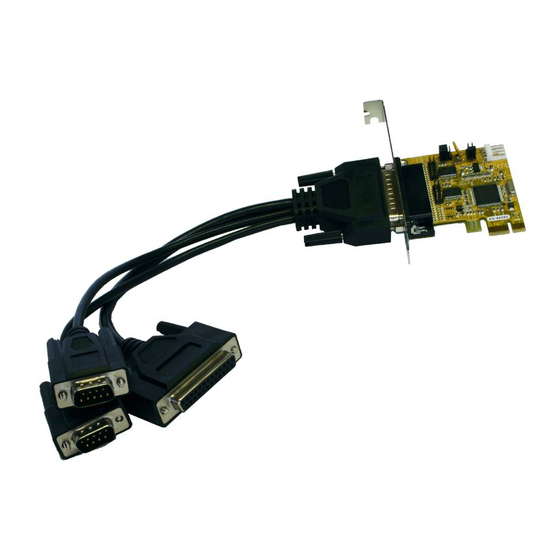
AUFBAU :
44 Pin D-Sub Buchse
für das Octopus-Kabel
S1:
9 Pin Seriell
Anschluss
P1:
25 Pin
parallel Anschluss
Bi-Direktional
S2:
9 Pin Seriell
Anschluss
BESCHREIBUNG & TECHNISCHE DATEN :
Die EX-44343 ist eine PCI-Express Multi I/O Karte mit einem Parallel Centronics EPP/
ECP Port und 2 seriellen FIFO 16C55x Ports, für den Anschluss von High-Speed seriel-
len RS-232 Peripherie Geräten (z.B. Terminal, Modem, Plotter usw.). Der serielle PCI-
Express Bus unterstützt dabei optimal die Leistung des schnellen 16C55x Chipsets mit
16byte FIFO Cache. Die EX-44343 gewährleistet so eine sichere Datenübertragung
und exzellente Performance von bis zu 115KBaud/s für jedes angeschlossene Gerät!
Sie unterstützt alle PCI-Express Slots von x1 bis x16. Es ist nicht möglich die I/O Adres-
sen und Interrupts manuell einzustellen, da die Einstellungen der Karte vom System
(BIOS) und beim Installieren des Betriebssystems automatisch vorgenommen werden.
Kompatibilität:
PCI-Express x1 bis x16
Betriebs Systeme:
DOS, WIN 9x/ME/NT4/2000/XP/Server 2003/Vista/7(Linux vom OS)
Anschlüsse:
2 x 9 Pin Sub-D Stecker, 1x 25 Pin Sub-D Parallel Buchse
Lieferumfang:
EX-44343, CD, Anleitung, 2 x 9 Pin Seriell und 1 x 25 Parallel
mit Octopus Kabel, LowProfile Bügel
CE
Zertifikate:
/ FCC / RoHS / WEEE
DE97424562 / WHQL
JUMPER EINSTELLUNG & ANSCHLÜSSE:
JP1:
DIS
= Am Pin 9 liegt das Standard Signal RI (Ring Indicator).
(Werkseinstellung)
DIS PWR
PWR
= Am Pin 9 kann jetzt eine Spannung von DC5V oder
DC12V eingestellt werden.
S1
S2
Die Einstellung der Spannung nehmen sie mit JP2 vor. Dies sollte aber
bei Standard Anwendungen nicht verstellt werden.
JP2:
Wenn sie den Jumper JP1 für S1 bis S4 auf PWR gesetzt haben,
können sie jetzt mit dem JP2 den Spannungswert einstellen. Es gibt 3
AUX5V
verschiedene Spannungsquellen. (Nur in Verbindung mit JP1 auf PWR!)
AUX12V
PCI12V
AUX 5V = 5Volt vom PC-Netzteil
AUX 12V = 12Volt vom PC-Netzteil
PCI 12V = 12Volt vom Mainboard (STANDARD)
J5:
1 +5V
2 GND
Für Strom vom Netzteil muss J5 mit PC Netzteil verbunden werden!
3 GND
4 +12V
1
JP1: Power auf 9 Pin Stecker
Ein/Aus
J5:
Anschluss für PC-Netzteil
JP2: Jumper für die
Stromquelle (Netzteil)
oder PCIe Bus
J2+J3:
10 Pin interner
Serieller Anschluss

Verwandte Anleitungen für Exsys EX-44343


Inhaltszusammenfassung für Exsys EX-44343
- Seite 1 “XP32_2K_2003“ and for Server 2003: “XP32_2K_2003“ or “XP64“ into the box for the Path/Source and click at >next/ Die EX-44343 ist eine PCI-Express Multi I/O Karte mit einem Parallel Centronics EPP/ continue<. Now Windows searches for the drivers in the specified directory. Follow the DB 44F: ECP Port und 2 seriellen FIFO 16C55x Ports, für den Anschluss von High-Speed seriel-...
- Seite 2 Treiber CD in Ihr CD-ROM Laufwerk (z.B. Laufwerk D:). Geben sie nun den Pfad "D:\IO\MOSCHIP\MCS9901\" und dann das Verzeichnis ihres Betriebssystems für The EX-44343 is a plug & play high-speed serial RS-232 expansion card for the PCI Server 2000: “XP32_2K_2003“ und für Server 2003: “XP32_2K_2003“ oder “XP64“...