Schartec Porte 150 Anleitung
24v dc

Verwandte Anleitungen für Schartec Porte 150


Inhaltszusammenfassung für Schartec Porte 150
- Seite 1 Anleitung Porte 150 Drehtorantrieb 24V DC für den privaten Bereich English manual begins on Page 13 Signalleuchte Drucktaster Steuerung...
-
Seite 2: Inhaltsverzeichnis
Inhalt Wichtige Sicherheitshinweise Introduction 2.1 Übersicht & Anwendung 2.2 Im Lieferumfang Enthalten Installation Vorbereitungen Installation des Steuerungskastens Vorbereitung Installation der Antriebsarme/ Motoren Installation der Motoren Technische Daten EU-Einbauerklärung... -
Seite 3: Wichtige Sicherheitshinweise
1. Wichtige Sicherheitshinweise 1.1 Bestimmungsgemäße Verwendung. Der Schartec Porte 150 Drehtor-Antrieb ist ausschließlich für den Betrieb von leichtgängigen Drehtoren im privaten, nicht gewerblichen Bereich vorgesehen. Die maximal zulässige Torgröße und das maximale Gewicht dürfen nicht überschritten werden. Das Tor muss sich leicht von Hand öffnen und schließen lassen. Regionale Windlasten sind bei Verwendung von Torfüllungen zu berücksichtigen (EN 13241-1). -
Seite 4: Weitere Wichtige Hinweise
1.7 Weitere wichtige Hinweise 1. Bitte lesen und befolgen Sie alle Sicherheitshinweise und Einbauempfehlungen. 2. Der Torantrieb ist den örtlichen Bestimmungen entsprechen entworfen und hergestellt worden. Der Installateur muss mit den örtlichen Vorschriften in Bezug auf die Installation des Drehtorantriebs vertraut sein. 3. -
Seite 5: Introduction
Spannungsversorgung für die Inbetriebnahme der Anlage beträgt 230 V. Für einen manuellen Betrieb des Drehtores müssen die beiden Motoren mit dem beiliegenden Schlüssel entriegelt werden. 2.2 Im Lieferumfang enthalten Bild 2 A) 2 Stk. Schartec Porte 150 Motoren B) Steuerung Porte P190 C) Lichtschranke Schartec SPC D) 2 Stk. Handsender Schartec SR-4... -
Seite 6: Installation Vorbereitungen
3. Installation Vorbereitungen Werkzeuge für die Installation Bitte stellen Sie sicher, dass die unten aufgeführten Werkzeuge zur Installation vorhanden sind. Bild 3 4. Installation des Steuerungskastens 1. Lösen Sie die Schrauben des Deckels und nehmen Sie diesen ab. 2. Die vier Befestigungspunkte für den Steuerungskasten befinden sich genau an der Position, an der der Deckel verschraubt ist. -
Seite 7: Vorbereitung Installation Der Antriebsarme/ Motoren
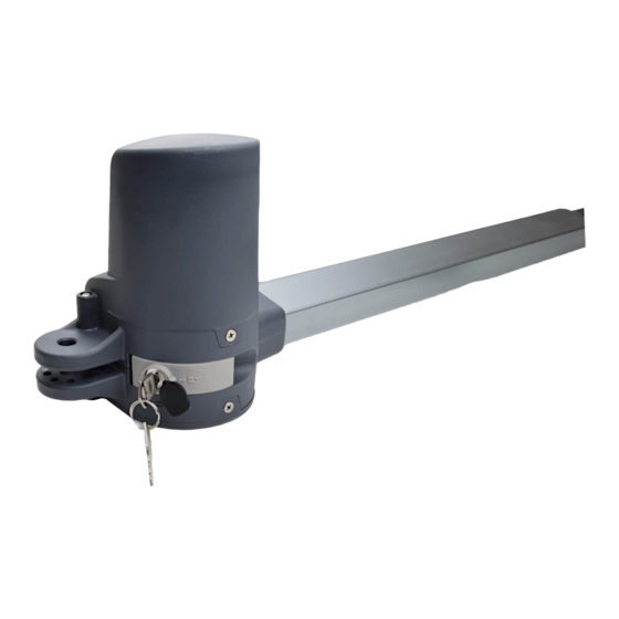
5. Vorbereitung Installation der Antriebsarme/ Motoren Hinweise zum Betrieb des Antriebes Der Drehtorantrieb Porte 150 ist für ein maximales Torflügelgewicht von 150 kg (je Flügel), eine maximale Torflügelbreite von 2 Meter (je Flügel), und eine maximale Torflügelhöhe von 2 Meter (je Flügel) ausgelegt. Der Öffnungswinkel beträgt bis zu 110°. - Seite 8 Achtung! A-Maß und B-Maß müssen zwingend eingehalten werden in dem angegebenen Bereich 130 - 190 mm (siehe Bild 7). Ansonsten kein einwandfreier Torlauf möglich. Folge: Steuerung stoppt Antrieb bereits während der Lernfahrt oder Antrieb reversiert im Betrieb. Bild 6 (Luftaufnahme) Porte 150 Bild 7 >120° 110°~120°...
-
Seite 9: Installation Der Motoren
6. Installation der Motoren 1. Wählen Sie die richtige Montageposition der Motoren. 2. Prüfen Sie ob die Montageflächen für die Halterungen eben und nach Wasserwaage ausgerichtet sind. 3. Legen Sie die Kabel für die Stromversorgung der Motoren. 4. Öffnen Sie die Schrauben am Motor und entfernen Sie die Abdeckung wie auf Bild 8. 5. - Seite 10 11. Befestigen Sie die vordere Halterung vorübergehend mit einer Schraubzwinge am Torflügel. 12. Verwenden Sie nun die Schlüssel um die Motoren zu entriegeln und die Kolben rauszuziehen 13. Heben Sie den Motor an und stecken Sie die Schraube in die vordere Motorhalterung. 14.
-
Seite 11: Technische Daten
26. Für die Entriegelung des rechten Motors müssen die obigen Schritte ebenfalls durchgeführt werden, jedoch in umgekehrten Drehrichtung. Bild 18 Bild 19 Bild 20 Bild 17 7. Technische Daten Porte 150 Motor 24 V DC mit mech. Entriegelung Getriebe Typ Wurmgetriebe Kraft 1500 N... -
Seite 12: Eu-Einbauerklärung
Schartec eine Marke der bau-shop-24 GmbH Fritz-Müller-Strasse 119 73730 Esslingen, Germany erklärt hiermit, dass die Torantriebe Porte 150, Porte 300, & Jet 500 in Übereinstimmung mit der − Maschinenrichtlinie 2006/42/EG − Niederspannungsrichtlinie 2014/35/EU − Richtlinie für elektromagnetische Verträglichkeit 2014/30/EU − RoHS Richtlinie 2011/65/EU −...