Herunterladen Inhalt Inhalt Diese Seite drucken

gc Labolight DUO Gebrauchsanweisung

Lichthärtungs-gerät mit dualer led-lichtquelle für indirekte komposite
Inhaltsverzeichnis

Werbung

Verfügbare Sprachen
  • DE

Verfügbare Sprachen

  • DEUTSCH, seite 32
Labolight DUO
LED Dual Mode Light Curing Unit for Indirect Composite Resin
EN
Lichthärtungs-Gerät mit dualer LED-Lichtquelle für indirekte Komposite
DE
Unité lumineuse LED à mode dual pour la photopolymérisation des résines composites indirectes
FR
Lampada LED a foto-polimerizzazione duale per resine composite da restauro indiretto
IT
Unidad de Fotopolimerización LED dual para resinas de composite indirecta
ES
Dwumodułowa lampa LED do polimeryzacji świetlnej żywic kompozytowych w technice pośredniej
PL
Instructions for Use
Gebrauchsanweisung
Mode d'emploi
Istruzioni per l'uso
Instrucciones de uso
Instrukcja obsługi
Downloaded from
www.Manualslib.com
manuals search engine

Werbung

Inhaltsverzeichnis
loading

Inhaltszusammenfassung für gc Labolight DUO

  • Seite 1 Labolight DUO LED Dual Mode Light Curing Unit for Indirect Composite Resin Lichthärtungs-Gerät mit dualer LED-Lichtquelle für indirekte Komposite Unité lumineuse LED à mode dual pour la photopolymérisation des résines composites indirectes Lampada LED a foto-polimerizzazione duale per resine composite da restauro indiretto Unidad de Fotopolimerización LED dual para resinas de composite indirecta...
  • Seite 2 Downloaded from www.Manualslib.com manuals search engine...
  • Seite 3 Labolight DUO LED DUAL MODE LIGHT CURING UNIT FOR INDIRECT COMPOSITE RESIN Prior to use, carefully read the instruction for use. Instructions for Use EN 1 Downloaded from www.Manualslib.com manuals search engine...
  • Seite 4: Inhaltsverzeichnis

    Table of contents 1. Introduction ............................EN 4 1.1 Intended use ..........................EN 4 1.2 Features ............................EN 4 1.3 Symbols ............................EN 5 2. For Safe Use of the Unit ........................EN 6 3. Product Description ..........................EN 8 3.1 Content of the package ........................
  • Seite 5 EN 3 Downloaded from www.Manualslib.com manuals search engine...
  • Seite 6: Introduction

    1.2 Features 1) Labolight DUO is a curing unit for dental professionals using LEDs as a light source. 2) Labolight DUO is mounted with 12 blue LEDs and 3 violet LEDs, enabling curing of any GC’s composite product. 3) Labolight DUO allows preliminary curing with the door open (step mode).
  • Seite 7 1.3 Symbols The symbols provided on this unit indicate the following meanings: Symbols Provision locations Meanings Caution Label Consult instruction for use. CAUTION : Visible radiation Caution Label Possibly hazardous optical radiation emitted from this product. Do not stare at operating lamp. May be harmful to the eyes. NOTICE : Ultraviolet radiation Caution Label UV emitted from this product.
  • Seite 8: Symbols

    Symbols Meanings Refer to this instructions for use. Disconnect mains plug from electrical outlet. Connect an earth terminal to the ground. 2. For Safe Use of the Unit Observe the following warnings and cautions for using the unit safely. WARNING ■...
  • Seite 9 CAUTION ■ Do not touch the LED unit and its surroundings after using the unit for a long time. Otherwise, burn injury could be caused. ■ Maintenance, if intended after a prolonged use, should be conducted after the unit temperature suffi ciently lowers.
  • Seite 10: Product Description

    3. Product Description 3.1 Content of the package Objekthalter Set Contents Quantity Labolight DUO Main body AC adapter Power cord Turntable Tray Curing stand holder Curing Plate Curing Stand Curing stand Silicone post for anterior Silicone post for posterior Metal post...
  • Seite 11: Names And Functions Of Parts

    3.2 Names and functions of Parts 3.2.1 Main body [A-2] [A-7] [A-8] [A-1] [A-3] [A-4] [A-10] [A-9] [A-11] [A-12] [A-6] [A-5] [A-14] [A-13] Name [A-1] Door [A-15] [A-2] Upper housing [A-3] Window [A-4] Handle [A-5] Control panel [A-16] [A-6] Lower housing [A-7] Visor fixing plate [A-17]...
  • Seite 12: Control Panel

    3.2.2 Control panel [B-1] [B-2] [B-4] [B-5] [B-6] [B-3] [B-7] [B-8] Name Information [B-1] Display Displays statuses of various devices. [B-2] Step mode indicator Lit during irradiation in the step mode. − Displays remaining time of irradiation in the step or full mode. −...
  • Seite 13: Ac Adapter And Power Cord

    3.2.3 AC adapter and Power cord Power cord AC plug DC plug Power indicator AC adapter : Lit when the AC adapter is supplied with power from a power suply. 3.2.4 Rating Plate / Caution Label < Rating Plate of the Main body > <...
  • Seite 14: Installation Method

    Verify all components are delivered prior to installation and assembly (see Section 3.1, “Content of the package”). In addition, check for any damage of the unit during transportation. Contact the dealer or GC in case any missing or damaged component is found. 4.3 Installation 1) Install the unit with care being taken for the following: −...
  • Seite 15: Assembly

    ■ Use the attached dedicated power cord and AC adapter. Note ● Only use genuine parts and accessories. Using other than genuine parts and accessories will cause termination of warranty and no more liability from GC. EN 13 Downloaded from www.Manualslib.com...
  • Seite 16: Startup And Checkup

    4.5 Startup and Checkup 1) Turn on the main switch with the door closed to verify the following: Time appears on the display. (see Item 3.2.2) 2) Press the step mode switch once with the door opened to verify the following: The step mode switch can be pressed.
  • Seite 17: Stoppage And Storage

    CAUTION ■ Do not continuously look inside the curing chamber through the window for a long time in the full mode. Otherwise, discomfort could be felt. CAUTION ■ In case the unit fails or damages, stop using the unit immediately, turn off the main switch, and pull out the power plug.
  • Seite 18: Use Method

    5. Use Method 5.1 Basic use method Note ● Verify normal operation of the unit prior to use. ● Pay special attention to the following during use of the unit: - Monitor the entire unit for any fault at all times. - In case of any fault found on the unit, take appropriate action such as shutting down the unit.
  • Seite 19: Step Mode

    3) After use, close the door and turn off the main switch. (see Section 4.6) CAUTION ■ Do not touch the LED unit and its surroundings after using the unit for a long time. Otherwise, burn injury could be caused. Note ●...
  • Seite 20: Full Mode

    < Recommended curing position in the step mode > Place a composite within the hatched area as shown in the diagram. (Hatched area: Inside the circle of about 40mm diameter directly above the turntable and besides ±10mm from the visor rim) + / - 10 mm Dia.
  • Seite 21 * Using the unit continuously for a long time may result in blinking of the overheat indicator due to excessively high temperature of LEDs. (Temperature warning) With the occurrence of temperature warning, it is recommended to conduct light irradiation for the maximum 5 minutes and then take intermission for the period equivalent to the irradiation time.
  • Seite 22: Use Method Of The Curing Stand Set

    2) A prosthesis or artifi cial tooth with a height of 52mm or less placed on a model Use “Curing plate” and “Curing stand holder” 70mm 52mm 70mm directly (Recommended curing position) 3) A prosthesis or artifi cial tooth with a height of 52mm or more placed on a model Place it together with the model on the turntable.
  • Seite 23: Maintenance

    6. Maintenance 6.1 Checkup Perform checkup and maintenance by taking the following recommended intervals as an indication: CAUTION ■ Be sure to perform regular checkup of the equipment and components. Contents Details After pressing the timer key with the door opened, verify Verifying LEDs being lit lighting of respective LEDs and proper rotation of the Verifying state of the turntable...
  • Seite 24: Cleaning Method Of Respective Portions

    CAUTION ■ Turn off the main switch and plug off the power cord prior to cleaning or parts replacement. 6.2.1 Cleaning method of respective portions CAUTION ■ Be sure to clean the curing chamber regularly, as otherwise, the contaminated chamber could not exercise suffi...
  • Seite 25: Method Of Removing/Remounting The Step Mode Switch Cover

    6.2.2 Method of removing / remounting the Step mode switch cover < Removal method > With the turntable removed, remove the cover by hooking the notches thereof on your fi ngers. < Mounting method > Align the protrusion of the step mode switch cover with the hole of the step mode switch plate and insert the protrusion into the hole.
  • Seite 26 < Mounting method > B(A) 4) As the front and back surfaces of the lens cover has a difference in profi les, ensure the proper orientation where the hole of the lens cover [D] aligns with the protrusion of the lens cover holder near the concave [B(A)].
  • Seite 27: Troubleshooting

    7. Troubleshooting Before requesting for repair based on your judgment of a failure on an event, conduct checking as follows. If nothing matches the following, contact your dealer or our branch or sales offi ce. Symptoms Causes Measures Check the main body, AC adapter, power cord, and Pulled out cords outlet for unsound connection.
  • Seite 28 Symptoms Causes Measures The unit may have detected excessively low or high temperature, or the temperature sensor may have failed. Immediately stop using the unit and check it for any defect. “E01” is displayed Defective temperature Use the unit in a temperature range of 10 to 40°C. on the display.
  • Seite 29: Warranty And Repair

    8. Warranty and Repair We take all possible care for manufacturing and quality of our product. Still, if you experience any failure of the product during the warranty period, we repair it without charge within the scope of the warranty as described. Contact your dealer or our branch or sales offi...
  • Seite 30: Disposal

    Please be aware that this product is compliant with the European Directive 2012 / 19 / EC (WEEE) and the laws applicable in your country for environmentally responsible recycling / disposal. Please ask GC Europe or your GC dealer when and where your product will have to be disposed of.
  • Seite 31 Labolight DUO LICHTHÄRTUNGS-GERÄT MIT DUALER LED-LICHTQUELLE FÜR INDIREKTE KOMPOSITE Vor der Verwendung die Gebrauchsanweisung sorgfältig lesen. Gebrauchsanweisung DE 1 Downloaded from www.Manualslib.com manuals search engine...
  • Seite 32 Inhalt 1. Einführung ............................DE 4 1.1 Verwendungszweck ........................DE 4 1.2 Eigenschaften ..........................DE 4 1.3 Symbole ............................DE 4 2. Sichere Verwendung des Geräts ......................DE 6 3. Produktbeschreibung ........................... DE 8 3.1 Packungsinhalt ..........................DE 8 3.2 Namen und Funktionen ........................DE 9 3.2.1 Haupteinheit ..........................
  • Seite 33 DE 3 Downloaded from www.Manualslib.com manuals search engine...
  • Seite 34: Einführung

    1) Labolight DUO ist ein LED-Lichthärtungsgerät für den dentalen Einsatz. 2) Labolight DUO umfasst 12 blaue und 3 violette LEDs und ist in der Lage, alle Kompositprodukte von GC zu härten. 3) Labolight DUO ermöglicht die Vorhärtung bei geöffneter Tür (Intervallmodus).
  • Seite 35 Symbole Befindet sich auf Bedeutung Netzschalter AUS (Power) Netzteil Wechselstrom Typenschild Gleichstrom Netzteil Typenschild Polarität des Gleichstromanschlusses Netzteil * Bezeichnungen finden Sie in Kapitel 3. Die in dieser Gebrauchsanweisung verwendeten Symbole haben folgende Bedeutung: Symbole Bedeutung WARNUNG: - Beachten Sie bei der Verwendung des Geräts die entsprechenden Warnhinweise, um Verletzungen und Sachschäden zu vermeiden.
  • Seite 36: Sichere Verwendung Des Geräts

    2. Sichere Verwendung des Geräts Beachten Sie die folgenden Warn- und Vorsichtshinweise für die sichere Verwendung des Geräts. WARNUNG ■ Dieses Gerät darf nur von qualifiziertem Fachpersonal bedient werden. ■ Lichtempfindliche Personen (Lichtallergiker) dürfen dieses Gerät nicht bedienen. Außerdem muss darauf geachtet werden, dass lichtempfindliche Personen (Lichtallergiker) sich nicht im Bereich der Lichteinstrahlung aufhalten.
  • Seite 37 VORSICHT ■ LED-Einheit und Umgebung nicht berühren, wenn das Gerät längere Zeit im Einsatz war. Verbrennungsgefahr. ■ Sollten nach längerer Nutzung Wartungsarbeiten erforderlich sein, muss das Gerät zunächst ausreichend abkühlen. VORSICHT < Allgemein > ■ Achten Sie darauf, das Gerät zu stabilisieren, beispielsweise im Hinblick auf Neigung, Vibration oder Stöße. ■...
  • Seite 38: Produktbeschreibung

    3. Produktbeschreibung 3.1 Packungsinhalt Objekthalter Set Inhalt Anzahl Labolight DUO Haupteinheit Netzteil Netzkabel Drehplatte Schale Objekthalter Objektplatte Objektständer Objekt- Silikonstift anterior halter-Set Silikonstift posterior Metallstift Klemme Lampenabdeckung (Ersatzteile / 3er-Pack) Gebrauchsanweisung DE 8 Downloaded from www.Manualslib.com manuals search engine...
  • Seite 39: Namen Und Funktionen

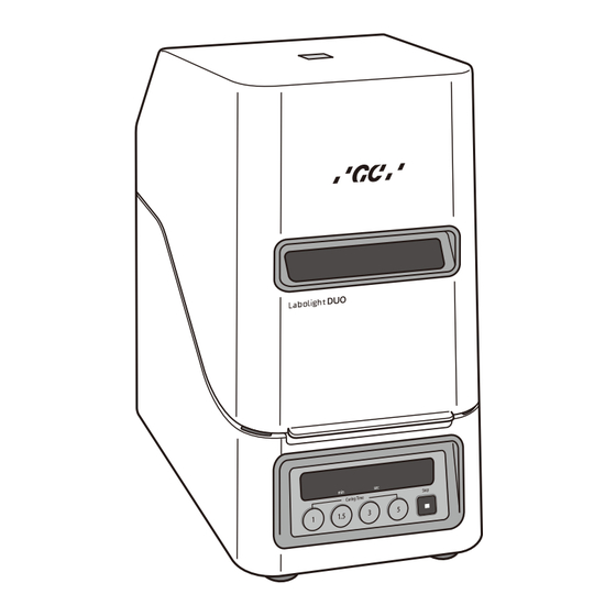
    3.2 Namen und Funktionen 3.2.1 Haupteinheit [A-2] [A-7] [A-8] [A-1] [A-3] [A-4] [A-10] [A-9] [A-11] [A-12] [A-6] [A-5] [A-14] [A-13] Name [A-1] Tür [A-15] [A-2] Oberes Gehäuse [A-3] Fenster [A-4] Griff [A-5] Bedienfeld [A-16] [A-6] Unteres Gehäuse [A-7] Fixierplatte Sichtschutz [A-17] [A-8] Sichtschutz...
  • Seite 40: Bedienfeld

    3.2.2 Bedienfeld [B-1] [B-2] [B-4] [B-5] [B-6] [B-3] [B-7] [B-8] Name Information [B-1] Display Zeigt den Status der unterschiedlichen Gerätefunktionen an. Anzeige [B-2] Leuchtet im Intervallmodus auf. Intervallmodus − Zeigt die verbleibende Beleuchtungszeit im Intervall- oder Vollmodus an. − Bei blinkender Zeitanzeige wurde das Gerät vorübergehend angehalten. Standby-Status bei geöffneter Tür (= Standby-Status im Intervallmodus) Standby-Status bei geschlossener Tür...
  • Seite 41: Netzteil Und Netzkabel

    3.2.3 Netzteil und Netzkabel Netzkabel Netzstecker Gleichstromstecker Stromanzeige Netzteil : Leuchtet auf, wenn das Netzteil mit Strom versorgt wird. 3.2.4 Typenschild / Hinweisschild < Typenschild der Haupteinheit > < Hinweisschild der Haupteinheit > DE 11 Downloaded from www.Manualslib.com manuals search engine...
  • Seite 42: Aufbau

    Überprüfen Sie vor dem Aufbau und der Montage, ob alle Komponenten vollständig sind (siehe Kapitel 3.1, „Packungsinhalt"). Untersuchen Sie außerdem alle Komponenten auf Transportschäden. Falls Sie fehlende oder beschädigte Komponenten finden, wenden Sie sich an Ihren Händler oder an GC. 4.3 Aufstellung 1) Achten Sie beim Aufbau auf folgende Punkte: −...
  • Seite 43: Montage

    ■ Achten Sie auf Frequenz, Spannung und zulässige Stromaufnahme (oder Energieverbrauch) der Stromquelle. ■ Verwenden Sie das mitgelieferte Netzkabel sowie das Netzteil. Hinweis ● Verwenden Sie nur Originalersatzteile und -zubehörteile. Andernfalls können der Gewährleistungsschutz und jegliche Haftung durch GC verfallen. DE 13 Downloaded from www.Manualslib.com...
  • Seite 44: Starten Und Überprüfen

    4.5 Starten und Überprüfen 1) Schalten Sie den Netzschalter bei geschlossener Tür auf EIN und überprüfen Sie folgende Punkte: Die Zeit wird angezeigt. (Siehe Kapitel 3.2.2) 2) Drücken Sie die Intervallmodus-Taste bei geöffneter Tür einmal, um folgende Punkte zu überprüfen: Die Intervallmodus-Taste kann gedrückt werden.
  • Seite 45: Ausschalten Und Aufbewahrung

    VORSICHT ■ Blicken Sie im Vollmodus nicht für längere Zeit kontinuierlich durch das Fenster in die Kammer. Andernfalls kann es zu Unwohlsein kommen. VORSICHT ■ Bei einer Fehlfunktion des Geräts oder wenn es beschädigt ist, darf das Gerät nicht mehr verwendet werden. Schalten Sie den Netzschalter aus und ziehen Sie das Kabel aus der Steckdose.
  • Seite 46: Verwendungsmethode

    5. Verwendungsmethode 5.1 Grundlegende Verwendungsmethode Hinweis ● Stellen Sie vor der Verwendung sicher, dass das Gerät ordnungsgemäß funktioniert. ● Achten Sie bei der Verwendung auf folgende Punkte: - Achten Sie stets auf mögliche Fehlfunktionen. - Reagieren Sie bei Fehlfunktionen entsprechend, beispielsweise indem Sie das Gerät ausschalten. WARNUNG ■...
  • Seite 47: Intervallmodus

    3) Schließen Sie nach der Verwendung die Tür und schalten Sie das Gerät mit dem Netzschalter aus. (Siehe Abschnitt 4.6) VORSICHT ■ LED-Einheit und Umgebung nicht berühren, wenn das Gerät längere Zeit im Einsatz war. Verbrennungsgefahr. Hinweis ● Wenn das Gerät für längere Zeit nicht verwendet wird, sollte das Netzkabel gezogen werden, um Strom zu sparen. 5.2 Intervallmodus Hinweis ●Verwenden Sie den Intervallmodus nur für die Zwischenhärtung.
  • Seite 48: Vollmodus

    < Empfohlene Aushärtposition im Intervallmodus > Halten Sie das Kompositmaterial in den Bereich, der in der Abbildung gestrichelt dargestellt ist. (Gestrichelter Bereich: In einem Umkreis von 40 mm Durchmesser direkt über der Drehplatte und ± 10 mm neben dem Sichtschutz) + / - 10 mm Dia.
  • Seite 49 * Wird das Gerät über einen längeren Zeitraum durchgehend verwendet, kann es vorkommen, dass die Überhitzungsanzeige blinkt, weil die LEDS zu heiß geworden sind. (Temperaturwarnung) Bei einer Temperaturwarnung sollte eine Beleuchtung maximal 5 Minuten lang erfolgen. Dann müssen Sie eine Pause machen, die in etwas so lange wie die Beleuchtung dauern sollte.
  • Seite 50: Verwenden Des Objektständer-Sets

    2) Prothese oder künstlicher Zahn mit maximal 52 mm Höhe auf einem Modell Verwenden Sie gegebenenfalls die Objektplatte und den Objekthalter. 70 mm 52mm 70 mm direkt (empfohlene Aushärtposition) 3) Prothese oder künstlicher Zahn mit mindestens 52 mm Höhe auf einem Modell Stellen Sie diese zusammen mit dem Modell auf die Drehplatte.
  • Seite 51: Wartung

    6. Wartung 6.1 Kontrolle Folgende Kontroll- und Wartungsintervalle werden empfohlen: VORSICHT ■ Überprüfen Sie das Gerät und seine Komponenten regelmäßig. Inhalt Details Wenn Sie die Timer-Taste bei geöffneter Tür drücken, können Sie die Funktionsfähigkeit der LEDs und der Funktionsfähigkeit der LEDs Drehplatte überprüfen.
  • Seite 52: Reinigen Und Austauschen Von Teilen

    6.2 Reinigen und Austauschen von Teilen Ziehen Sie den Netzstecker, damit sich das Gerät während der Reinigung oder dem Auswechseln von Teilen nicht versehentlich einschaltet. VORSICHT ■ Sollten nach längerer Nutzung Wartungsarbeiten erforderlich sein, muss das Gerät zunächst ausreichend abkühlen. VORSICHT ■...
  • Seite 53: Entfernen/Anbringen Der Abdeckung Der Intervallmodus-Taste

    Hinweis ● Verwenden Sie zum Reinigen des Geräts ein weiches, leicht mit Wasser oder Alkohol angefeuchtetes Tuch. Verwenden Sie keine organischen Reinigungsmittel (Verdünner, Benzin usw.). ● Organische Reiniger können zum Ausfärben des Geräts führen. Sollten solche Reiniger auf das Gerät gelangen, entfernen Sie sie umgehend.
  • Seite 54: Fehlerbehebung

    < Anbringen > B(A) 4) Vorder- und Rückseite der Lampenabdeckung unterscheiden sich. Daher müssen Sie auf eine korrekte Ausrichtung achten: Die Öffnung der Lampenabdeckung [D] muss in Richtung Ausbuchtung des Halters in der Nähe der Auskerbung [B(A)] weisen. 5) Biegen Sie die Abdeckung etwas nach außen und führen Sie die Ausbuchtung [rechter Winkel] der Lampenabdeckung [E] in die Seiten des Halter [C] ein.
  • Seite 55 Symptome Ursachen Maßnahmen Warten Sie mit dem Neustart, bis die LED(s) Vorübergehendes Die Überhitzungs- abgekühlt sind. Ausschalten des Geräts anzeige leuchtet Tritt dieser Fehler häufig auf, wenden Sie sich an wegen überhitzter auf. Ihren Händler bzw. an unsere Niederlassung oder LED(s) das Vertriebsbüro.
  • Seite 56 Symptome Ursachen Maßnahmen Die Einheit hat eine zu hohe/zu niedrige Temperatur festgestellt oder der Temperatursensor ist defekt. Halten Sie das Gerät sofort an und suchen Sie nach Fehlern. Das Gerät sollte bei einer Umgebungstemperatur „E01" wird Defekter von 10 bis 40°C verwendet werden. angezeigt.
  • Seite 57: Gewährleistung Und Reparatur

    8. Gewährleistung und Reparatur Wir legen größten Wert auf eine hochwertige Verarbeitung und Qualität unserer Produkte. Wenn während des Gewährleistungszeitraums dennoch Fehlfunktionen auftreten sollten, reparieren wir das Gerät kostenlos wie beschrieben im Rahmen der Gewährleistung. Wenden Sie sich nach Bedarf an Ihren Händler bzw. an unsere Niederlassung oder das Vertriebsbüro.
  • Seite 58: Entsorgung

    Bitte beachten Sie, dass dieses Produkt der EU-Richtlinie 2012 / 19 / EG (WEEE) und den jeweiligen nationalen Gesetzen für eine umweltgerechte Wiederverwertung / Entsorgung unterliegt. Fragen Sie bei GC Europe oder Ihrem GC Händler nach, wann und wo Ihr Produkt entsorgt werden muss. 10. Technische Daten...
  • Seite 59 Labolight DUO UNITÉ LUMINEUSE LED À MODE DUAL POUR LA PHOTOPOLYMÉRISATION DES RÉSINES COMPOSITES INDIRECTES Veuillez lire attentivement le mode d'emploi avant toute utilisation. Mode d’emploi FR 1 Downloaded from www.Manualslib.com manuals search engine...
  • Seite 60 Table des matières 1. Introduction ............................FR 4 1.1 Utilisation prévue ..........................FR 4 1.2 Caractéristiques ..........................FR 4 1.3 Symboles ............................FR 4 2. Pour utiliser l’unité en toute sécurité ....................... FR 6 3. Description du produit ..........................FR 8 3.1 Contenu de l’emballage ........................
  • Seite 61 FR 3 Downloaded from www.Manualslib.com manuals search engine...
  • Seite 62: Introduction

    1) Le Labolight DUO est une unité de polymérisation réservée aux professionnels des soins dentaires dotée de LED en guise de source lumineuse. 2) Le Labolight DUO est doté de 12 LED bleues et 3 LED violettes permettant de polymériser n'importe quel produit composite de GC.
  • Seite 63 Symboles Emplacements Signification ATTENTION : La surface peut être chaude. Unité LED ■ Ne touchez pas l'unité LED et ses alentours après une utilisation prolongée de l'unité. Vous risqueriez de vous brûler. Interrupteur principal ON (mise sous tension) Interrupteur principal OFF (mise hors tension) Adaptateur CA Courant alternatif...
  • Seite 64: Pour Utiliser L'unité En Toute Sécurité

    2. Pour utiliser l’unité en toute sécurité Respectez les mises en garde et les avertissements suivants pour utiliser l’unité en toute sécurité. AVERTISSEMENT ■ Seul un personnel qualifi é en soins dentaires est autorisé à utiliser cette unité. ■ Il est interdit aux membres du personnel souffrant de photosensibilité – notamment d'une allergie à la lumière –...
  • Seite 65 ATTENTION ■ Ne touchez pas l’unité LED et ses alentours après une utilisation prolongée de l’unité. Vous risqueriez de vous brûler. ■ L’entretien de l’unité après une longue utilisation doit être effectué après avoir laissé cette dernière refroidir suffi samment. ATTENTION <...
  • Seite 66: Description Du Produit

    3. Description du produit 3.1 Contenu de l’emballage Objekthalter Set N° Contenu Quantité Boîtier principal du Labolight Duo Adaptateur CA Câble d’alimentation Plateau tournant Plateau Porte-support de polymérisation Plaque de polymérisation Support de polymérisation du support Support en silicone pour dent antérieure polymérisation...
  • Seite 67: Noms Et Fonctions Des Pièces

    3.2 Noms et fonctions des pièces 3.2.1 Boîtier principal [A-2] [A-7] [A-8] [A-1] [A-3] [A-4] [A-10] [A-9] [A-11] [A-12] [A-6] [A-5] [A-14] [A-13] N° [A-1] Porte [A-2] Boîtier supérieur [A-15] [A-3] Fenêtre [A-4] Poignée [A-5] Panneau de commande [A-6] Boîtier inférieur [A-16] [A-7] Plaque de fixation de la visière...
  • Seite 68: Panneau De Commande

    3.2.2 Panneau de commande [B-1] [B-2] [B-4] [B-5] [B-6] [B-3] [B-7] [B-8] N° Information [B-1] Écran d'affichage Affiche le statut des divers dispositifs. Indicateur du mode par [B-2] Allumé en cours d'irradiation en mode par étape. étape − indique la durée d'irradiation restante en mode par étape ou pleine puissance.
  • Seite 69: Adaptateur Ca Et Câble D'alimentation

    3.2.3 Adaptateur CA et câble d'alimentation Câble d’alimentation Prise CA Prise CC Témoin de mise sous/hors tension Adaptateur CA : Allumé lorsque l'adaptateur est alimenté par une source de courant. 3.2.4 Plaque signalétique / Étiquette de mise en garde < Plaque signalétique du boîtier principal > <...
  • Seite 70: Méthode D'installation

    Assurez-vous de la livraison de tous les composants avant l'installation et l'assemblage (voir section 3.1 « Contenu de l'emballage »). Contrôlez également l'unité pour repérer tout endommagement éventuel occasionné lors du transport. Contactez le revendeur ou GC pour tout composant manquant ou endommagé. 4.3 Installation 1) Installez l'unité...
  • Seite 71: Assemblage

    ■ Utilisez le câble d'alimentation et l'adaptateur CA fournis. Remarque ● Utilisez uniquement les pièces et les accessoires d'origine. L'utilisation de pièces et d'accessoires autres que ceux d'origine mettra fi n à la garantie et exonèrera GC de toute responsabilité. FR 13 Downloaded from www.Manualslib.com...
  • Seite 72: Démarrage Et Vérifi Cation

    4.5 Démarrage et vérifi cation 1) Activez l'interrupteur principal, la porte fermée, pour vérifi er ce qui suit : Le temps est affi ché. (voir point 3.2.2) 2) Appuyez une seule fois sur l'interrupteur du mode par étape, la porte ouverte, pour vérifi er ce qui suit : L'interrupteur du mode par étape peut être activé.
  • Seite 73: Arrêt Et Stockage

    ATTENTION ■ En mode pleine puissance, ne regardez pas à l'intérieur de la chambre de polymérisation à travers la fenêtre pendant une longue période. Dans le cas contraire, cela pourrait vous incommoder. ATTENTION ■ Si l'unité est défectueuse ou endommagée, cessez immédiatement de l'utiliser, mettez-la hors tension et retirez le câble d'alimentation.
  • Seite 74: Méthode D'utilisation

    5. Méthode d'utilisation 5.1 Méthode d'utilisation de base Remarque ● Assurez-vous du fonctionnement normal de l'unité avant de l'utiliser. ● Faites particulièrement attention à ce qui suit en cas d'utilisation de l'unité : - contrôlez constamment l'unité afi n de repérer toute anomalie éventuelle. - en cas de détection d'une anomalie quelconque, prenez des mesures appropriées, y compris l'arrêt de l'unité.
  • Seite 75: Mode Par Étape

    ATTENTION ■ Assurez-vous de la parfaite polymérisation du matériau une fois celle-ci terminée. En cas de polymérisation insuffi sante, prolongez la durée d'émission de la lumière d'irradiation. ■ Enlevez les saletés de la protection de la lentille ou remplacez la protection sale. La partie sale risquerait en effet de chauffer et de déformer ou de faire fondre la protection.
  • Seite 76: Mode Pleine Puissance

    3) Une fois l'irradiation légère terminée, retirez l'objet soumis à polymérisation. * Une utilisation prolongée de l'unité peut entraîner le clignotement de l'indicateur de surchauffe en raison d'une température excessive des LED (avertissement de température). En cas d'activation de l'alarme de température, il est recommandé...
  • Seite 77 ATTENTION ■ Si un élément quelconque se retrouve coincé par le plateau tournant, arrêtez sa rotation en appuyant sur l'interrupteur d'arrêt ou en actionnant l'interrupteur principal avant d'enlever l'objet coincé. * Pour arrêter une polymérisation en cours, appuyez sur le bouton d'arrêt. L'unité passera en état de veille. * Pour arrêter temporairement une polymérisation, ouvrez la porte en cours de traitement ou appuyez sur le bouton de la minuterie avec la porte ouverte.
  • Seite 78 1) Prothèse seule (couronne et bridge par exemple) / Prothèse sur un modèle muni d'une broche radiculaire Utilisez le « support de polymérisation » et le « porte-support de polymérisation ». (Pour un complément d'information sur le support de polymérisation, voir la section 5.4) 70 mm 55 mm 70 mm directement...
  • Seite 79: Méthode D'utilisation Du Kit Du Support De Polymérisation

    5.4 Méthode d'utilisation du kit du support de polymérisation Pour une prothèse seule, telle qu'une couronne et un bridge, ou celle placée sur un modèle muni d'une broche radiculaire, disposez-la à l'aide du support de polymérisation et divers supports, en fonction des divers exemples d'utilisation.
  • Seite 80: Nettoyage Et Remplacement Des Pièces

    Éléments Détails Une lentille fortement décolorée, sale ou rayée peut Remplacement de la protection occasionner une anomalie de la polymérisation. S'il s'avère de la lentille (Intervalle de impossible de restaurer une lentille décolorée, contaminée ou Remplacement remplacement à titre d'indication : rayée, il convient de la remplacer.
  • Seite 81 Élements Détails À nettoyer avec un chiffon doux imbibé d'un peu d'eau ou d'alcool. * S'il s'avère impossible de restaurer une lentille décolorée, contaminée ou rayée, il convient de la remplacer. * La protection de la lentille peut se décolorer au fil du temps. ATTENTION Protection de la lentille...
  • Seite 82: Méthode De Dépose/Pose Du Couvre-Interrupteur Du Mode Par Étape

    6.2.2 Méthode de dépose / pose du couvre-interrupteur du mode par étape < Méthode de dépose > Une fois le plateau tournant enlevé, retirez la protection en saisissant les encoches avec vos doigts. < Méthode de pose > Alignez l'ergot du couvre-interrupteur du mode par étape sur l'orifi ce de la plaque de l'interrupteur du mode par étape et insérez-le dans l'orifi...
  • Seite 83 < Méthode de pose > B(A) 4) Les surfaces avant et arrière de la protection de la lentille ayant des profi ls différents, assurez-vous que l'orientation est correcte : le trou de la protection de la lentille [D] doit être aligné sur l'ergot du support de la protection de la lentille près du creux [B(A)].
  • Seite 84: Dépannage

    7. Dépannage Avant de demander une réparation de ce que vous considérez être une défaillance, procédez aux vérifi cations ci-dessous. Si aucun des symptômes évoqués ne correspond, contactez votre distributeur, notre division ou notre service des ventes. Symptômes Causes Mesures Vérifier le boîtier principal, l'adaptateur CA, le câble Câbles débranchés d'alimentation et la prise secteur afin de repérer...
  • Seite 85 Symptômes Causes Mesures L'intensité lumineuse peut être réduite en cas de L'affichage est saleté ou de rayures des composants optiques. normal et toutes Saleté ou rayures des Nettoyer l'intérieur de la chambre de polymérisation Lumière les LED sont composants optiques. et la protection de la lentille, ou remplacer la excessivement allumées.
  • Seite 86: Garantie Et Réparations

    AVERTISSEMENT ■ Ne jamais démonter ou modifi er l'unité. Cela pourrait entraîner une production de chaleur, un incendie ou la rupture de l’unité. ATTENTION ■ Si l'unité est défectueuse ou endommagée, cessez immédiatement de l'utiliser, mettez-la hors tension et retirez le câble d'alimentation. ■...
  • Seite 87: Mise Au Rebut

    à la législation applicable dans votre pays pour un recyclage / une mise au rebut dans le respect de l'environnement. Veuillez consulter GC Europe ou votre distributeur GC afi n de déterminer quand et où mettre votre produit au rebut.
  • Seite 88 Downloaded from www.Manualslib.com manuals search engine...
  • Seite 89 Labolight DUO LAMPADA LED A FOTO-POLIMERIZZAZIONE DUALE PER RESINE COMPOSITE DA RESTAURO INDIRETTO Prima dell'uso, leggere attentamente le istruzioni per l'uso. Istruzioni per l'uso IT 1 Downloaded from www.Manualslib.com manuals search engine...
  • Seite 90 Indice 1. Introduzione ............................IT 4 1.1 Uso previsto ............................IT 4 1.2 Caratteristiche ........................... IT 4 1.3 Simboli .............................. IT 4 2. Utilizzo sicuro dell'unità ..........................IT 6 3. Descrizione del prodotto .......................... IT 8 3.1 Contenuto della confezione ........................ IT 8 3.2 Nomi e funzioni dei componenti ......................
  • Seite 91 IT 3 Downloaded from www.Manualslib.com manuals search engine...
  • Seite 92: Introduzione

    1) Labolight DUO è un fotopolimerizzatore per operatori professionisti basato sui LED come sorgente luminosa. 2) Labolight DUO è provvista di 12 LED blu e 3 LED viola, che permettono di fotopolimerizzare qualsiasi prodotto composito di GC. 3) Labolight DUO consente la polimerizzazione preliminare con lo sportello aperto (modalità passo a passo).
  • Seite 93 Simboli Posizione Significato ATTENZIONE: la superficie potrebbe essere rovente. ■ Per un abbondante lasso di tempo dopo avere utilizzato l'unità, Unità LED non toccare l'unità LED e la zona circostante per non rischiare di ustionarsi. Interruttore principale ACCESO (alimentazione) Interruttore principale SPENTO (alimentazione) Alimentatore CA Corrente alternata...
  • Seite 94: Utilizzo Sicuro Dell'unità

    2. Utilizzo sicuro dell'unità Per utilizzare l'unità in modo sicuro, rispettare le seguenti avvertenze e precauzioni. AVVISO ■ L'uso dell'unità è consentito soltanto a personale qualifi cato per le cure dentali. ■ Vietare l'utilizzo dell'unità al personale fotosensibile, ad esempio coloro che sono allergici alla luce. Fare inoltre attenzione a non dirigere la luce irradiata verso persone fotosensibili, come le persone allergiche alla luce.
  • Seite 95 ATTENZIONE < Generale > ■ Verifi care la stabilità dell'unità controllandone ad esempio l'inclinazione, le vibrazioni e l'impatto. ■ Se l'unità si guasta o viene danneggiata, smettere subito di utilizzarla, spegnere l'interruttore principale ed estrarre la presa di corrente. ■ Non cercare di riparare da soli l'unità guasta, ma chiedere a un esperto di farlo dopo avere fornito le indicazioni appropriate.
  • Seite 96: Descrizione Del Prodotto

    3. Descrizione del prodotto 3.1 Contenuto della confezione Objekthalter Set Contenuto Quantità Labolight DUO, corpo principale Alimentatore CA Cavo di alimentazione Piattello rotante Vassoio Portasupporto per il polimerizzatore Piastra di polimerizzazione Supporto per il polimerizzatore Set di supporti per il...
  • Seite 97: Nomi E Funzioni Dei Componenti

    3.2 Nomi e funzioni dei componenti 3.2.1 Corpo principale [A-2] [A-7] [A-8] [A-1] [A-3] [A-4] [A-10] [A-9] [A-11] [A-12] [A-6] [A-5] [A-14] [A-13] Nome [A-1] Sportello [A-15] [A-2] Alloggiamento superiore [A-3] Finestra [A-4] Maniglia [A-5] Quadro di controllo [A-16] [A-6] Alloggiamento inferiore [A-7] Targhetta fissaggio visore...
  • Seite 98: Quadro Di Controllo

    3.2.2 Quadro di controllo [B-1] [B-2] [B-4] [B-5] [B-6] [B-3] [B-7] [B-8] Nome Funzione [B-1] Display Mostra lo stato dei vari dispositivi. Indicatore modalità [B-2] Acceso durante l'irradiazione in modalità passo passo. passo passo − Indica il tempo di irradiazione mancante in modalità passo passo o completa. −...
  • Seite 99: Adattatore Ca E Cavo Di Alimentazione

    3.2.3 Adattatore CA e cavo di alimentazione Cavo di alimentazione Spina CA Spina CC Indicatore di alimentazione Alimentatore CA : acceso quando l'adattatore CA riceve corrente dall'alimentatore. 3.2.4 Targhetta / Etichetta delle avvertenze < Targhetta del corpo principale > < Etichetta delle avvertenze del corpo principale > IT 11 Downloaded from www.Manualslib.com...
  • Seite 100: Metodo Di Installazione

    (v. paragrafo 3.1 "Contenuto della confezione"). Controllare inoltre che l'unità non abbia subito danni durante il trasporto. Se si nota che alcuni componenti mancano o sono danneggiati, rivolgersi al proprio rivenditore o a GC. 4.3 Installazione 1) Installare l'unità adottando i seguenti accorgimenti: −...
  • Seite 101: Montaggio

    Nota ● Utilizzare soltanto parti di ricambio e accessori originali. L'utilizzo di parti di ricambio e accessori non originali invalida la garanzia ed esonera GC dalle sue responsabilità. 4.5 Messa in funzione e controllo 1) Accendere l'interruttore principale con lo sportello chiuso per verifi care quanto segue: Il tempo viene visualizzato sul display (vedere il paragrafo 3.2.2)
  • Seite 102 2) Premere l'interruttore della modalità passo passo con lo sportello aperto per verifi care quanto segue: È possibile premere l'interruttore della modalità passo passo. Una volta rilasciato, l'interruttore torna nella posizione originale. Sono accesi soltanto i LED della fi la in alto. * Durante quest'operazione, non tenere lo sguardo direttamente sui LED.
  • Seite 103: Spegnimento E Conservazione

    Nota ● Dopo un lungo periodo di fermo, prima di utilizzare l'unità controllare che funzioni in modo normale e sicuro. 4.6 Spegnimento e conservazione 1) Chiudere lo sportello e spegnere l'interruttore principale. Nota ● Se l'unità non viene utilizzata a lungo, si consiglia di staccare il cavo di alimentazione per risparmiare energia.
  • Seite 104 AVVISO ■ Vietare l'utilizzo dell'unità al personale fotosensibile, ad esempio coloro che sono allergici alla luce. Fare inoltre attenzione a non dirigere la luce irradiata verso persone fotosensibili, come le persone allergiche alla luce. ■ L'unità non deve essere utilizzata da personale portatore di pacemaker, per non compromettere il funzionamento del pacemaker.
  • Seite 105: Modalità Passo Passo

    Nota ● Se l'unità non viene utilizzata a lungo, si consiglia di staccare il cavo di alimentazione per risparmiare energia. 5.2 Modalità passo passo Nota ● Utilizzare la modalità passo passo soltanto per la polimerizzazione preliminare. 1) Aprire lo sportello e controllare che l'indicatore sportello aperto sia acceso. (stato di standby in modalità...
  • Seite 106: Modalità Completa

    < Posizione di polimerizzazione consigliata in modalità passo passo > Mettere il composito nell'area tratteggiata, come illustrato nella fi gura. (Area tratteggiata: dentro a un cerchio di circa 40 mm di diametro subito sopra il piattello rotante e + / - 10 mm Dia.
  • Seite 107 * Se si utilizza l'unità in modo continuativo a lungo, l'indicatore di surriscaldamento può lampeggiare a causa di una temperatura troppo elevata dei LED. (avviso temperatura) Quando compare l'avviso di temperatura, si consiglia di proseguire con l'irradiazione per 5 minuti al massimo e di fare una pausa di durata pari all'irradiazione.
  • Seite 108: Metodo Di Utilizzo Del Set Di Supporti Per La Polimerizzazione

    2) Protesi o dente artifi ciale dall'altezza massima di 52 mm su un modello Utilizzo della "piastra di polimerizzazione" e del "portasupporto per il polimerizzatore" 70 mm 52 mm Direttamente 70 mm (posizione di polimerizzazione consigliata) 3) Protesi o dente artifi ciale dall'altezza minima di 52 mm su un modello Metterli sul piattello rotante insieme al modello.
  • Seite 109: Manutenzione

    6. Manutenzione 6.1 Controllo Eseguire il controllo e la manutenzione con la seguente frequenza consigliata: ATTENZIONE ■ Controllare regolarmente le apparecchiature e i componenti. Contenuto Dettagli Dopo aver premuto il tasto del timer con lo sportello aperto, verificare che i LED si illuminino e che il piattello Verificare che i LED si accendano rotante giri correttamente.
  • Seite 110: Metodo Di Pulitura Dei Pezzi

    ATTENZIONE ■ Spegnere l'interruttore principale e staccare il cavo di corrente prima della pulizia o della sostituzione dei pezzi. 6.2.1 Metodo di pulitura dei pezzi ATTENZIONE ■ Pulire regolarmente la camera di polimerizzazione: se è sporca non è garantito un funzionamento ottimale. Contenuto Dettagli Pulire con un panno morbido inumidito con una piccola quantità...
  • Seite 111: Metodo Di Rimozione/Rimontaggio Del Coperchio Dell'interruttore Della Modalità Passo Passo

    6.2.2 Metodo di rimozione / rimontaggio del coperchio dell'interruttore della modalità passo passo < Metodo di rimozione > Con il piattello rotante rimosso, rimuovere il coperchio prendendolo dalle tacche. < Metodo di montaggio > Allineare la sporgenza del coperchio dell'interruttore della modalità passo passo al foro della piastra dell'interruttore della modalità...
  • Seite 112: Risoluzione Dei Problemi

    < Metodo di montaggio > B[A] 4) Dato che le superfi ci anteriore e posteriore del coperchio della lente hanno profi li diversi, controllare che l'orientamento sia corretto nel punto in cui il foro del coperchio della lente [D] è allineato alla sporgenza del supporto del coperchio della lente vicino alla cavità...
  • Seite 113 Sintomi Cause Misure Sostituire l'alimentatore CA / o il cavo di Alimentatore CA o alimentazione. cavo di alimentazione Rivolgersi al proprio rivenditore o al nostro ufficio Quando si accende l'interruttore difettoso vendite o filiale. principale, l'unità non si accende (non compare nulla sul display).
  • Seite 114 Sintomi Cause Misure È possibile che la temperatura nell'unità sia eccessivamente alta o bassa oppure che il sensore della temperatura sia guasto. Smettere subito di usare l'unità e controllare che non sia difettosa. Sul display Sensore di temperatura Utilizzare l'unità in un intervallo di temperatura tra compare la scritta difettoso 10 e 40°C.
  • Seite 115: Garanzia E Riparazione

    8. Garanzia e riparazione Dedichiamo il massimo impegno alla produzione e alla qualità dei prodotti. Tuttavia, in caso di guasti dei prodotti durante il periodo di garanzia, ripariamo gratuitamente il prodotto se coperto da garanzia alle condizioni indicate. Eventualmente rivolgersi al proprio rivenditore o al nostro uffi cio vendite o fi liale. Come produttore, non ci assumiamo alcuna responsabilità...
  • Seite 116: Smaltimento

    Il prodotto è conforme alla Direttiva Europea 2012 / 19 / UE (RAEE) e alle leggi in vigore nel vostro paese sul riciclaggio / smaltimento ecologico dei rifi uti. Chiedere a GC Europe o al proprio rivenditore GC quando e dove verrà smaltito il prodotto.
  • Seite 117 Labolight DUO UNIDAD DE FOTOPOLIMERIZACIÓN LED DUAL PARA RESINAS DE COMPOSITE INDIRECTA Lea detenidamente las instrucciones antes de utilizar la unidad. Instrucciones de uso ES 1 Downloaded from www.Manualslib.com manuals search engine...
  • Seite 118 Contenido 1. Introducción ............................ES 4 1.1 Uso previsto ........................... ES 4 1.2 Características ..........................ES 4 1.3 Símbolos ............................ES 4 2. Para el uso seguro del aparato ......................ES 6 3. Descripción del producto ........................ES 8 3.1 Contenido del paquete ........................ES 8 3.2 Nombres y funciones de los componentes ..................
  • Seite 119 ES 3 Downloaded from www.Manualslib.com manuals search engine...
  • Seite 120: Introducción

    1) Labolight DUO es un aparato de polimerización para profesionales dentales que utiliza la iluminación emitida por luces LED. 2) Labolight DUO dispone de 12 LED azules y 3 LED violeta, que permiten polimerizar cualquier producto de composite de GC.
  • Seite 121 Símbolo Lugar donde aparece Significado PRECAUCIÓN: La superficie puede estar caliente. ■ No debe tocarse la unidad de LED ni las zonas circundantes después Unidad de LED de un tiempo prolongado de funcionamiento. De lo contrario, pueden producirse quemaduras. Interruptor principal ON (encendido) Interruptor principal OFF (apagado)
  • Seite 122: Para El Uso Seguro Del Aparato

    2. Para el uso seguro del aparato Respete las siguientes precauciones y advertencias para utilizar este aparato con seguridad. ADVERTENCIA ■ Este aparato solo debe ser utilizado por personal cualifi cado para la administración de tratamientos dentales. ■ El personal con problemas de fotosensibilidad, como las personas con alergia a la luz, no debe utilizar este aparato. Además, se deben tomar precauciones para evitar que la luz irradiada incida sobre personas fotosensibles, es decir, con alergia a la luz.
  • Seite 123 PRECAUCIÓN ■ No debe tocarse la unidad de LED ni las zonas circundantes después de un tiempo prolongado de funcionamiento. De lo contrario, pueden producirse quemaduras. ■ El mantenimiento, sobre todo si se realiza después de un uso prolongado, se debe llevar a cabo cuando la temperatura haya disminuido lo sufi...
  • Seite 124: Descripción Del Producto

    3. Descripción del producto 3.1 Contenido del paquete Conjunto de soporte de polimerización N.º Contenido Cantidad Cuerpo principal del Labolight DUO Adaptador de corriente alterna Cable de alimentación Plato giratorio Bandeja Porta soporte de polimerización Plato de polimerización Soporte de polimerización...
  • Seite 125: Nombres Y Funciones De Los Componentes

    3.2 Nombres y funciones de los componentes 3.2.1 Cuerpo principal [A-2] [A-7] [A-8] [A-1] [A-3] [A-4] [A-10] [A-9] [A-11] [A-12] [A-6] [A-5] [A-14] [A-13] N.º Nombre [A-1] Puerta [A-15] [A-2] Alojamiento superior [A-3] Ventana [A-4] [A-5] Panel de control [A-16] [A-6] Alojamiento inferior [A-7]...
  • Seite 126: Panel De Mandos

    3.2.2 Panel de mandos [B-1] [B-2] [B-4] [B-5] [B-6] [B-3] [B-7] [B-8] N.º Nombre Información [B-1] Pantalla Muestra el estado de diversos dispositivos. Indicador de modo [B-2] Se enciende durante la irradiación en el modo progresivo. progresivo − Muestra el tiempo de irradiación restante en el modo progresivo o completo. −...
  • Seite 127: Adaptador De Corriente Alterna Y Cable De Alimentación

    3.2.3 Adaptador de corriente alterna y cable de alimentación Cable de alimentación Enchufe de corriente alterna Conector de corriente continua Adaptador de Indicador de alimentación corriente alterna : Se enciende cuando el adaptador de corriente alterna está conectado a una fuente de alimentación. 3.2.4 Placa de características / etiqueta de precaución <...
  • Seite 128: Método De Instalación

    3.1, “Contenido del paquete”). Confi rme también que el aparato no ha sufrido ningún daño durante el transporte. Si falta algún componente o ha sufrido daños, póngase en contacto con el distribuidor o con GC. 4.3 Instalación 1) Instale el aparato teniendo en cuenta lo siguiente: −...
  • Seite 129: Montaje

    ■ Use el cable de alimentación específi co del aparato y su adaptador de corriente alterna. Nota ● Utilice únicamente piezas y accesorios originales. El uso de piezas y accesorios no originales dará lugar a la extinción de la garantía y anulará cualquier responsabilidad por parte de GC. ES 13 Downloaded from www.Manualslib.com...
  • Seite 130: Puesta En Funcionamiento Y Comprobaciones

    4.5 Puesta en funcionamiento y comprobaciones 1) Encienda el interruptor principal, con la puerta cerrada, para verifi car lo siguiente: Aparece el tiempo en la pantalla. (vea el Apartado 3.2.2) 2) Pulse una vez el interruptor de modo progresivo con la puerta abierta para verifi car lo siguiente: Puede pulsar el interruptor de modo progresivo.
  • Seite 131: Parada Y Almacenamiento

    PRECAUCIÓN ■ No mire de una manera continua y prolongada el interior de la cámara de polimerización a través de la ventanilla cuando esté activado el modo completo. Puede causar malestar. PRECAUCIÓN ■ Si el aparato sufre daños o problemas de funcionamiento, deje de utilizarlo de manera inmediata, apague el interruptor principal y desconecte el enchufe de alimentación.
  • Seite 132: Método De Funcionamiento

    5. Método de funcionamiento 5.1 Método de funcionamiento básico Nota ● Antes del uso, compruebe que el aparato funciona con normalidad. ● Preste especial atención a lo siguiente durante el uso del aparato: - Esté siempre atento a cualquier posible avería del polimerizador. - En caso de avería, tome las medidas apropiadas como, por ejemplo, apagar la unidad.
  • Seite 133 PRECAUCIÓN ■ Ajuste un tiempo de polimerización adecuado para el material utilizado. ■ Compruebe siempre que el material se ha polimerizado perfectamente al terminar de procesarlo. En caso de una polimerización insufi ciente, puede irradiarlo de nuevo. ■ Limpie la contaminación de la tapa de la lente o sustituya la tapa contaminada. De lo contrario, la parte contaminada se calentará...
  • Seite 134: Modo Progresivo

    3) Al fi nalizar la irradiación luminosa, extraiga el objeto que se ha polimerizado. * Si el aparato se utiliza durante un tiempo prolongado, puede comenzar a parpadear el indicador de sobrecalentamiento, a causa de la alta temperatura que alcanzan los LED (advertencia de temperatura). Si aparece la advertencia de alta temperatura, se recomienda hacer una pausa por un periodo equivalente al tiempo de polimerización anterior.
  • Seite 135 PRECAUCIÓN ■ Si algún objeto queda atrapado por el plato giratorio, detenga la rotación antes de extraer el objeto atrapado. Para ello, pulse el interruptor de parada o apague el interruptor principal. * Pulse el botón de parada si desea detener la polimerización durante el proceso. Se activará el estado de espera.
  • Seite 136: Uso Del Método Del Conjunto De Soporte De Polimerización

    1) Una prótesis individual como una corona y puente / Una prótesis colocada en un modelo con perno Uso del “Soporte de polimerización” y el “Porta soporte de polimerización” (Para obtener más información acerca del Pedestal de polimerización, consulte la Sección 5.4) 70 mm 55 mm 70 mm directamente...
  • Seite 137 soporte de polimerización Pinza Sujeta una prótesis y se inserta en un agujero redondo o tres orifi cios redondos contiguos del soporte de polimerización. Espiga metálica Recibe una prótesis y se inserta en un agujero redondo o tres orifi cios redondos contiguos del soporte de polimerización. Espiga de silicona Recibe una prótesis y se inserta en un agujero hexagonal del soporte de polimerización.
  • Seite 138: Mantenimiento

    PRECAUCIÓN ■ Limpie la cámara de polimerización con regularidad, ya que, de no hacerlo, la contaminación de la cámara podría disminuir la efi ciencia del proceso. Si se utiliza un desinfectante infl amable (por ejemplo, a base de alcohol isopropílico), la lámpara no se debe encender mientras aun queden vapores en la cámara, ya que existe el riesgo de incendio o explosión.
  • Seite 139: Método Para Desmontar/Volver A Montar La Tapa Del Interruptor Del Modo Progresivo

    Contenido Detalles Limpie con un paño suave humedecido ligeramente con agua o alcohol. Si se acumula suciedad en un hueco, retire la tapa Interruptor de del interruptor de modo progresivo y limpie con, por modo progresivo ejemplo, un bastoncillo de algodón. (Consulte el método de extracción en el Apartado 6.2.3) Visor...
  • Seite 140: Método Para Montar La Tapa De La Lente

    6.2.3 Método para montar la tapa de la lente < Preparación > 1) Apague la alimentación y desenchufe el adaptador de corriente alterna. 2) Extraiga el plato giratorio y tienda el cuerpo principal sobre uno de sus lados. < Método de extracción > 3) Inserte una uña o unas pinzas en el espacio formado [A] entre el soporte y la tapa de la lente a través de la concavidad del soporte, y deslice la tapa hacia la parte cóncava [A].
  • Seite 141: Solución De Problemas

    6) Deslice la tapa de la lente para montarla. 7) Confi rme que los salientes del soporte de la tapa de la lente [B] estén acoplados con el orifi cio de la tapa [D]. 7. Solución de problemas Antes de solicitar la reparación de una aparente avería, lleve a cabo las siguientes comprobaciones. Si su problema no coincide con ninguno de los que aparecen en la siguiente tabla, póngase en contacto con su distribuidor o con nuestra sucursal u ofi...
  • Seite 142 Síntomas Causas Medidas El indicador de Detención temporal por Antes de volver a poner en funcionamiento el sobrecalentamiento sobrecalentamiento de aparato, espere a que se enfríen los LED. está encendido y uno o varios LED (La Si se repite un problema con frecuencia, póngase el tiempo restante irradiación se detiene de en contacto con su distribuidor o con nuestra...
  • Seite 143 Síntomas Causas Medidas Puede que la unidad haya detectado una temperatura excesivamente alta o baja, o que el sensor de temperatura no funcione. Interrumpa inmediatamente el uso del aparato y compruebe si tiene algún defecto. Se muestra “E01” en Sensor de temperatura Use el aparato en un rango de temperaturas de entre la pantalla.
  • Seite 144: Garantía Y Reparación

    8. Garantía y reparación Adoptamos todas las medidas posibles para garantizar la fabricación de productos de calidad. No obstante, si el producto que ha comprado presenta alguna avería durante el periodo de garantía, lo repararemos sin coste alguno para usted dentro del marco descrito para la garantía. Póngase en contacto con su distribuidor o con nuestra sucursal u ofi...
  • Seite 145: Eliminación

    Este producto cumple con la Directiva europea 2012 / 19 / UE (RAEE) y la legislación vigente en su país en materia de reciclaje / eliminación de una forma respetuosa con el medio ambiente. Pregunte a GC Europe o a su distribuidor de GC cuándo y dónde debe eliminar su producto. 10. Características técnicas...
  • Seite 146 Downloaded from www.Manualslib.com manuals search engine...
  • Seite 147: Instrukcja Obsługi

    Labolight DUO DWUMODUŁOWA LAMPA LED DO POLIMERYZACJI ŚWIETLNEJ ŻYWIC KOMPOZYTOWYCH W TECHNICE POŚREDNIEJ Przed rozpoczęciem użytkowania należy dokładnie przeczytać instrukcję obsługi. Instrukcja obsługi PL 1 Downloaded from www.Manualslib.com manuals search engine...
  • Seite 148 Spis treści 1. WprowadzenieIntroducción ........................PL 4 1.1 Przeznaczenie ..........................PL 4 1.2 Charakterystyka ..........................PL 4 1.3 Symbole ............................PL 4 2. Bezpieczna obsługa urządzenia ......................PL 6 3. Opis produktu ............................PL 8 3.1 Zawartość opakowania ........................PL 8 3.2 Nazwy i funkcje części ........................
  • Seite 149 PL 3 Downloaded from www.Manualslib.com manuals search engine...
  • Seite 150: Przeznaczenie

    1.2 Charakterystyka 1) Labolight DUO jest opartym na diodach LED urządzeniem stomatologicznym do utwardzania światłem. 2) Urządzenie Labolight DUO jest wyposażone w 12 niebieskich i 3 fi oletowe diody LED, które umożliwiają utwardzanie wszystkich produktów kompozytowych GC. 3) Labolight DUO pozwala na wstępne utwardzanie przy otwartych drzwiczkach (tryb wstępny).
  • Seite 151 Symbole Umiejscowienie Znaczenie Wyłącznik główny ON (Zasilanie włączone) Wyłącznik główny OFF (Zasilanie wyłączone) Zasilacz AC Prąd przemienny Tabliczka znamionowa Prąd stały Zasilacz AC Tabliczka znamionowa Polaryzacja złącza zasilania prądem stałym Zasilacz AC * Opisy poszczególnych części, patrz rozdział 3. Symbole pojawiające się w niniejszej instrukcji mają następujące znaczenie: Symbole Znaczenie OSTRZEŻENIE:...
  • Seite 152: Bezpieczna Obsługa Urządzenia

    2. Bezpieczna obsługa urządzenia Dla zapewnienia bezpiecznej obsługi urządzenia należy stosować się do poniższych ostrzeżeń i uwag. OSTRZEŻENIE ■ Urządzenie obsługiwać może wyłącznie wykwalifi kowany personel stomatologiczny. ■ Urządzenia nie mogą obsługiwać osoby wrażliwe na światło, np. z alergią na światło. Ponadto należy zapewnić, aby osoby wrażliwe na światło, np.
  • Seite 153 UWAGA < Zalecenia ogólne > ■ Należy zapewnić stabilność urządzenia, na przykład pod względem nachylenia, wibracji lub wstrząsów. ■ W przypadku usterki lub uszkodzenia należy natychmiast zaprzestać pracy z urządzeniem, wyłączyć główny wyłącznik i wyciągnąć wtyczkę zasilającą. ■ Nie należy podejmować samodzielnych prób naprawy urządzenia, ale zlecić to ekspertowi posiadającemu odpowiednie kwalifi...
  • Seite 154: Opis Produktu

    3. Opis produktu 3.1 Zawartość opakowania Zestaw stanowiska do utwardzania Zawartość Liczba Główna jednostka Labolight DUO Zasilacz AC Przewód zasilający Płyta obrotowa Taca Uchwyt podstawki do utwardzania Płytka do utwardzania Podstawka do utwardzania Zestaw stanowiska Sztyft silikonowy przedni utwardzania Sztyft silikonowy tylny...
  • Seite 155: Nazwy I Funkcje Części

    3.2 Nazwy i funkcje części 3.2.1 Główna jednostka [A-2] [A-7] [A-8] [A-1] [A-3] [A-4] [A-10] [A-9] [A-11] [A-12] [A-6] [A-5] [A-14] [A-13] Nazwa [A-1] Drzwiczki [A-15] [A-2] Górna część obudowy [A-3] Okienko [A-4] Uchwyt [A-5] Panel sterowania [A-16] [A-6] Dolna część obudowy [A-7] Płytka mocująca osłony [A-17]...
  • Seite 156: Panel Sterowania

    3.2.2 Panel sterowania [B-1] [B-2] [B-4] [B-5] [B-6] [B-3] [B-7] [B-8] Nazwa Informacja [B-1] Wyświetlacz Wyświetla status różnych urządzeń. Wskaźnik trybu [B-2] Świeci się podczas naświetlania w trybie wstępnym. wstępnym − Wyświetla pozostały czas naświetlania w trybie wstępnym lub pełnym. −...
  • Seite 157: Zasilacz Ac I Przewód Zasilający

    3.2.3 Zasilacz AC i przewód zasilający Przewód zasilający Wtyczka AC Wtyczka DC Kontrolka zasilania Zasilacz AC : Świeci się, gdy zasilacz AC jest zaopatrywany w energię ze źródła zasilania. 3.2.4 Tabliczka znamionowa / tabliczka ostrzegawcza < Tabliczka znamionowa na głównej jednostce urządzenia > <Tabliczka ostrzegawcza na głównej jednostce urządzenia >...
  • Seite 158: Sposób Instalacji

    4. Sposób instalacji 4.1 Transport Wskazówka ● Na czas transportu urządzenie należy dobrze zabezpieczyć, aby ochronić je przed wstrząsami. ● Należy używać odpowiedniego materiału opakowaniowego. Wszystkie materiały opakowaniowe powinny zostać odpowiednio zutylizowane lub poddane recyklingowi, zgodnie z aktualnie obowiązującymi przepisami. 4.2 Rozpakowywanie Przed przystąpieniem do instalacji i montażu należy sprawdzić, czy dostarczone zostały wszystkie komponenty (patrz rozdział...
  • Seite 159: Montaż

    ■ Należy używać dołączonego przewodu zasilającego i zasilacza AC. Wskazówka ● Należy używać wyłącznie oryginalnych części i akcesoriów. Użycie części i akcesoriów innych niż oryginalne jest równoznaczne z utratą gwarancji i zwolnieniem GC od odpowiedzialności. PL 13 Downloaded from www.Manualslib.com...
  • Seite 160: Uruchomienie I Czynności Kontrolne

    4.5 Uruchomienie i czynności kontrolne 1) Przy zamkniętych drzwiczkach włączyć główny wyłącznik, aby sprawdzić poniższe: Czy na wyświetlaczu pojawia się czas? (patrz punkt 3.2.2) 2) Przy otwartych drzwiczkach nacisnąć raz przełącznik trybu wstępnego, aby sprawdzić poniższe: Czy można nacisnąć przełącznik trybu wstępnego, a po puszczeniu wraca on do położenia początkowego? Czy świecą...
  • Seite 161: Zatrzymanie I Przechowywanie

    UWAGA ■ Nie należy patrzeć przez dłuższy czas bez przerwy przez okienko komory utwardzania w trybie pełnym. W przeciwnym wypadku może pojawić się dyskomfort. UWAGA ■ W przypadku usterki lub uszkodzenia należy natychmiast zaprzestać pracy z urządzeniem, wyłączyć główny wyłącznik i wyciągnąć wtyczkę zasilającą. Wskazówka ●...
  • Seite 162: Sposób Obsługi

    5. Sposób obsługi 5.1 Podstawowy sposób obsługi Wskazówka ● Przed przystąpieniem do obsługi należy sprawdzić czy urządzenie pracuje prawidłowo. ● Podczas użytkowania urządzenia należy: - Nieustannie kontrolować całe urządzenie pod kątem usterek. - W przypadku usterek podjąć odpowiednie działania, takie jak wyłączenie urządzenia. OSTRZEŻENIE ■...
  • Seite 163: Tryb Wstępny

    UWAGA ■ Po zakończeniu procesu utwardzania należy sprawdzić, czy materiał został całkowicie utwardzony. W przypadku niewystarczającego utwardzenia należy przedłużyć naświetlanie. ■ Zanieczyszczoną osłonę soczewki należy oczyścić lub wymienić. W przeciwnym razie zanieczyszczenia mogą się nagrzewać, prowadząc do odkształcenia lub topienia osłony. 3) Po zakończeniu użytkowania zamknąć...
  • Seite 164: Tryb Pełny

    3) Po zakończeniu naświetlania usunąć utwardzany obiekt. * Przy długotrwałym użytkowaniu urządzenia może zacząć migać wskaźnik przegrzania na skutek zbyt wysokiej temperatury diod LED (ostrzeżenie temperaturowe). W przypadku ostrzeżenia temperaturowego zaleca się zrobienie przerwy na czas odpowiadający uprzedniemu czasowi utwardzania. * Dalszy wzrost temperatury będzie prowadził...
  • Seite 165 UWAGA ■ W przypadku wciągnięcia czegokolwiek przez płytę obrotową należy przed usunięciem zablokowanego przedmiotu zatrzymać płytę, naciskając przycisk Stop lub główny wyłącznik. * Aby przerwać trwające właśnie utwardzanie, należy nacisnąć przycisk zatrzymania. Urządzenie przejdzie w stan gotowości. * Jeśli podczas utwardzania otwarte zostaną drzwiczki lub przy otwartych drzwiczkach naciśnięty zostanie przycisk programatora czasowego, nastąpi tymczasowe wstrzymanie utwardzania.
  • Seite 166 1) Pojedyncze uzupełnienie protetyczne, takie jak korona lub most / Uzupełnienie protetyczne na modelu wyposażonym w pin ustalający Należy użyć podstawki do utwardzania i uchwytu podstawki do utwardzania. (Więcej informacji szczegółowych dotyczących podstawki do utwardzania znaleźć można w rozdziale 5.4) 70 mm 55 mm 70 mm, bezpośrednio...
  • Seite 167: Praca Z Zestawem Stanowiska Do Utwardzania

    5.4 Praca z zestawem stanowiska do utwardzania W przypadku pojedynczego uzupełnienia protetycznego, takiego jak korona lub most, bądź modelu wyposażonego w pin ustalający należy użyć podstawki do utwardzania i różnych sztyftów, biorąc pod uwagę poniższe przykłady zastosowania. Podstawka do utwardzania Zacisk Mocuje utwardzany obiekt.
  • Seite 168: Czyszczenie I Wymiana Części

    UWAGA ■ Należy pamiętać o regularnym czyszczeniu komory utwardzania. Zanieczyszczona komora nie pozwala osiągnąć odpowiedniej wydajności utwardzania. Jeśli zastosowany zostanie środek dezynfekujący palny (np. na bazie alkoholu izopropylowego), w komorze gromadzić się będą opary, które mogą być źródłem zapłonu/wybuchu przy włączaniu lampy. Wskazówka ●...
  • Seite 169: Sposób Demontażu/Ponownego Montażu Osłony Przełącznika Trybu Wstępnego

    Zawartość Informacje szczegółowe Przetrzeć, używając miękkiej szmatki zwilżonej małą ilością wody lub alkoholu. Brud zgromadzony w szczelinie należy Przełącznik trybu wyczyścić za pomocą na przykład bawełnianego wstępnego wacika, usuwając uprzednio osłonę przełącznika trybu wstępnego. (Sposób demontażu opisano w punkcie 6.2.3.) Osłona Przetrzeć, używając miękkiej szmatki zwilżonej małą...
  • Seite 170: Sposób Wymiany Osłony Soczewki

    6.2.3 Sposób wymiany osłony soczewki < Przygotowanie > 1) Wyłączyć zasilanie i odłączyć zasilacz AC. 2) Wymontować płytę obrotową i położyć główny korpus na boku. < Sposób demontażu > 3) Wetknąć paznokieć lub pincetę do szczeliny [A] między uchwytem soczewki i osłoną soczewki przez zagłębienie w uchwycie, a następnie wsunąć...
  • Seite 171: Rozwiązywanie Problemów

    6) Wsunąć osłonę soczewki w celu montażu. 7) Sprawdzić, czy występy uchwytu osłony soczewki [B] współpracują z otworem osłony soczewki [D]. 7. Rozwiązywanie problemów Przed zażądaniem naprawy w oparciu o własną ocenę usterki lub zdarzenia należy najpierw wykonać poniższe czynności kontrolne. Jeśli żadna z przyczyn nie pokrywa się z poniższymi, należy skontaktować się z dostawcą, oddziałem lub biurem sprzedaży.
  • Seite 172 Oznaki Przyczyny Rozwiązania Tymczasowe Świeci się Przed ponownym uruchomieniem należy poczekać wstrzymanie za sprawą wskaźnik na ostygnięcie diod LED. przegrzania diod LED przegrzania i na Jeśli problem pojawia się często, należy (Tymczasowo wyświetlaczu miga skontaktować się z dostawcą, oddziałem lub biurem wstrzymane pozostały czas.
  • Seite 173 Oznaki Przyczyny Rozwiązania Urządzenie mogło wykryć zbyt niską lub zbyt wysoką temperaturę albo uszkodzony może być czujnik temperatury. Należy natychmiast zaprzestać pracy z urządzeniem i sprawdzić je pod kątem uszkodzeń. Na wyświetlaczu Uszkodzony czujnik Urządzenie może pracować w temperaturze od 10 wyświetla się...
  • Seite 174: Gwarancja I Naprawa

    8. Gwarancja i naprawa Do produkcji i jakości naszych produktów przywiązujemy szczególną wagę. Jeśli mimo to podczas okresu gwarancji pojawią się jakiekolwiek wady, zostaną usunięte w ramach gwarancji za darmo. Odpowiednio do potrzeb należy skontaktować się z dostawcą, oddziałem lub biurem sprzedaży. Jako producent nie ponosimy odpowiedzialności za żadne zdarzenia, takie jak uszkodzenia spowodowane użytkowaniem tego urządzenia w sposób niezgodny z przeznaczeniem lub nie stosowaniem się...
  • Seite 175: Utylizacja

    Uwaga: produkt jest zgodny z Dyrektywą Europejską 2012 / 19 / EC (WEEE) i przepisami dotyczącymi recyklingu / utylizacji w sposób przyjazny dla środowiska w danym kraju. Aby uzyskać informacje na temat czasu i miejsca utylizacji produktu, należy skontaktować się z GC Europe lub swoim dostawcą GC. 10. Dane techniczne Nazwa / Model Labolight DUO Niebieska dioda LED: 12 (4 x 3 zespoły)
  • Seite 176 Manufactured by GC CORPORATION 76-1 Hasunuma-cho, Itabashi-ku, Tokyo 174-8585, Japan EU: GC EUROPE N.V. Researchpark Haasrode-Leuven 1240, Interleuvenlaan 33, B-3001 Leuven, Belgium TEL: +32 16 74 10 00 US: GC AMERICA INC. 3737 West 127th Street, Alsip, Illinois 60803 U.S.A.

Inhaltsverzeichnis