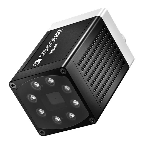
SENSOPART VISOR Installationsanleitung
Vision-sensor
Vorschau ausblenden
Andere Handbücher für VISOR:
- Benutzerhandbuch (639 Seiten) ,
- Kommunikationshandbuch (253 Seiten)
Quicklinks
VISOR
®
Installationsanleitung
VISOR
Installation guide
®
Guide d'installation VISOR
®
VISOR
Vision-Sensor
Vision sensor
Capteur de vision
068-14730 30.03.2020-05
www.sensopart.com
D
SICHERHEITSHINWEISE
Vor Inbetriebnahme die Betriebsanleitung lesen. Anschluss, Montage, Einstellung und
Inbetriebnahme nur durch Fachpersonal. Kein Sicherheitsbauteil gemäß EU-Maschi-
nenrichtlinie (nicht zum Schutz von Personen geeignet).
Einsatz nicht im Außenbereich.
Anschlussleitungen sind vom Hersteller erhältlich. Siehe Produktinformationen oder
wenden Sie sich an den Kundenservice.
Das Gerät muss aus einer "class 2" Quelle versorgt werden.
BESTIMMUNGSGEMÄSSE VERWENDUNG
Sensor wird zum optischen, berührungslosen Erfassen von Objekten eingesetzt.
LIEFERUMFANG
VISOR
®
Vision-Sensor, Installationsanleitung, Montageklammer (MK 45), Inbus-
schlüssel, Schraubendreher, Schutzkappe für Ethernetstecker.
D
SICHTFELDGRÖSSE / OBJEKTABSTAND
Focal length: 6mm V10
150
x direction
y direction
100
50
0
-50
-100
Format WVGA
-150
0
50
100
150
200
250
Working Distance[mm]
D
ELEKTRISCHER ANSCHLUSS
GB
ELECTRICAL CONNECTION
DATA Cable
1
4
902-51813 CI L5FG-S-2m-PUR
2
Direct connection
3
LAN Cable
5
902-51754 CI L4MG/RJ45G-GS-3m-PUR
Network connection
LAN Cable
902-51754 CI L4MG/RJ45G-GS-3m-PUR
Power / I/O Cable
ACHTUNG
Nur geschirmte Kabel verwenden und Schirm großflächig auflegen. Anzugsdrehmoment für Stecker 0,6 - 1 Nm.
ATTENTION
Only use shielded cables and apply shield over a large area. Tightening torque for plug 0.6 - 1Nm.
ATTENTION
Utilisez uniquement des câbles blindés et raccordez le blindage sur une grande surface. Couple de serrage
0,6 - 1 Nm.
D
GB
MECHANISCHE INSTALLATION
MECHANICAL INSTALLATION
MK 45 (543-11000)
(Content of delivery)
Accessories, PC software, documentation, and support available at www.sensopart.com.
D
TECHNISCHE DATEN (TYP)
Elektrische Daten
Betriebsspannung U
B
Restwelligkeit
Stromaufnahme (ohne I/O)
Alle Eingänge
Eingangswiderstand
Encodereingang
Ausgänge
Max. Ausgangsstrom (je Ausgang)
Kurzschlussschutz (alle Ausgänge)
Induktive Last
Verpolschutz U
B
Schnittstellen VISOR
®
Bereitschaftsverzug
Optische Daten
Pixel Anzahl, Chipgröße,
Pixelgröße
Technologie
Eingebaute Messbeleuchtung
®
Eingebautes Objektiv, Brennweite
Objektiv (einstellbar bis ∞ )
Mindest-Messabstand [mm]
Mindest-Sichtfeld X x Y [mm]
Mechanische Daten
Länge x Breite x Höhe
Gewicht
Vibration / Schock
Betriebsumgebungstemperatur
Lagertemperatur
Schutzart
Steckeranschluss
Gehäusematerial
GB
SAFETY INSTRUCTIONS
Read operating instructions before start-up. Connection, assembly, setting and
start-up only by trained personnel. No safety component according to EU machinery
directives (not suited for the protection of personnel).
Not for outdoor use.
Adapters providing field wiring means are available from the manufacturer. Refer to
manufacturers information.
The device shall be supplied from a class 2 rated power supply.
INTENDED USE
Sensor is used for the optical, non-contact detection of objects.
COMPONENTS SUPPLIED
VISOR
®
vision sensor,
(MK 45), allen key, screwdriver, and protective cap for Ethernet plug.
F
GB
FIELD OF VIEW / OBJECT DISTANCE
HAUTEUR DU CHAMP DE VUE / DISTANCE DE L'OBJET
Focal length: 12mm V10
150
x direction
y direction
100
50
0
-50
-100
Format WVGA
-150
300
0
100
200
300
400
Working Distance[mm]
F
RACCORDEMENT ÉLECTRIQUE
Network-
switch
902-51801 C L12FG-S-2m-PUR
F
MONTAGE MÉCHANIQUE
MG 3A (543-11024)
GB
F
TECHNICAL DATA (TYPE)
DONNÉES TECHNIQUES (TYPE)
Electrical data
Caractéristiques électriques
Operating voltage U
Tension d'alimentation U
B
Residual ripple
Ondes résiduelles
Current consumption (no I/O)
Consommation (sans I/O Box)
All inputs
Entrées
Input resistance
Résistance d'entrée
Encoder input
Entrée codeur
Outputs
Sorties
Maximum output current (per output) Courant de sortie maximum (par sortie)
Short-circuit protection (all outputs)
Protection court-circuits (toutes les sorties)
Inductive load
Charge inductive
Reverse-polarity protection U
Protection contre les inversions de polarité U
B
Interfaces VISOR
Interfaces VISOR
®
Power-on Delay
Temps de démarrage
Optical data
Caractéristiques optiques
Number of pixels, chip size,
Nombre de pixel, taille de la puce,
pixel size
la taille du pixel
Technology
Techno de capteur
Integrated scan illumination
Éclairage interne
Integrated lens, focal length
Objectif intégré, focale
Lens (adjustable to infinity)
Objectif (réglable jusqu'a l'infini)
Min. scan distance [mm]
Distance de travail min [mm]
Min. field of view X x Y [mm]
Champ de vue min X x Y [mm]
Mechanical data
Caract. mécaniques
Length x width x height
Longueur x Largeur x Hauteur
Weight
Poids
Vibration / shock
Vibrations / Chocs
Ambient operating temperature
Condition de travail
Storage temperature
Condition de stockage
Enclosure rating
Indice de protection
Plug connection
Type de connecteurs
Housing material
Matériau du boîtier
installation
guide, mounting clamp
Focal length: 25mm V10
150
x direction
y direction
100
50
0
-50
-100
Format WVGA
-150
500
600
700
0
250
500
Working Distance[mm]
1 D
GB
LED-Anzeige
Pwr Grün (Betriebsspannung)
Green (Operating voltage) Vert (Alimentation)
A
Gelb (Ergebnis 1)
Yellow (Result 1)
B
Gelb (Ergebnis 2)
Yellow (Result 2)
C
Gelb (Ergebnis 3)
Yellow (Result 3)
2 D
GB
Fokussierschraube
Bildscharfstellung
Focus
Uhrzeigersinn =
Clockwise =
größerer Objektabstand
higher distance
Gegen Uhrzeigersinn =
Counter Clockwise = lower
kleinerer Objektabstand
distance
D
24 V DC, I/O-ANSCHLUSS, M12
3
F
24 V DC, CONNECTEUR I/O, M12
PIN COL. USE
1
BN
+ U
(24 V DC)
B
2
BU
GND
3
WH
IN (external trigger)
4
GN
READY
5
PK
IN / OUT (advanced:
2
A - coded
encoder B+)
6
2
YE
IN / OUT
*1 Ready: Ready for next ext. trigger.
*2 Switchable input - output
*3 VALID: shows available results
*4 All LEDs are set without taking into account any timing function (e.g. trigger delay).
For shielded cables use shield.
D
GB
VISOR
VISION-SENSOR
VISOR
®
D
VISOR
®
VISION-SENSOR C-MOUNT
24 V DC, -25 % / +10 %
B
< 5 Vss
≤ 200 mA
PNP / NPN High > U
> 20 kOhm
High > 4 V
PNP / NPN
50 mA, Ejector (Pin 12 / RDBU) 100 mA
Yes
Typ.: Relais 17 K / 2 H, Pneumatic valve 1.4 K / 190 mH
Yes
B
Ethernet (LAN), RS422/RS232, depends on model
®
Typ. 13 s after Power on
VISOR
- V10...: 736 (H) x 480 (V), 1/3", 6,0 µm square
®
VISOR
- V20...: 1280 (H) x 1024 (V), 1/1.8", 5,3 µm square
®
CMOS (mono / color)
8 LEDs (except C-Mount) White, Red (620 nm), IR (850 nm)
6, 12 or 25 mm, focal position adjustable
V10, 6 mm
6
5 x 4
65 mm x 45 mm x 45 mm (without plug)
Approx... 160 g
EN 60947-5-2
0 °C ... 50 °C (80 % air humidity, noncondensing)
-20 °C ... 60 °C (80 % air humidity, noncondensing)
IP 65 / IP 67
24 V DC and I/O: M12 12-pin; LAN: M12 4-pin; Data: M12 5-pin
Aluminium, plastic
F
INSTRUCTIONS DE SÉCURITÉ
Lire les instructions de service avant mise en service. Raccordement, assemblage,
réglage et mise en service ne doivent être effectués que par du personnel qualifié.
Il ne s'agit pas de pièces de sécurité selon les directives européennes en vigueur
concernant les machines (inappropriées à la protection de personnes).
Ne pas utiliser à l'extérieur.
Les câbles de raccordement peuvent être obtenus du fabricant. Voir les informations
produits ou contacter le service clients.
L'appareil doit être impérativement alimenté par une alimentation CLASS 2.
UTILISATION CONFORME
Le capteur est utilisé pour la détection optique des objets sans contact.
COMPOSANTS FOURNIS
Capteur de vision VISOR
®
,
guide
d'installation, 1 pince de montage (MK 45), 1 clé 6
pans, 1 tournevis et 1 protection pour le connecteur Ethernet.
Focal length: 12mm V20
250
x direction
200
y direction
150
100
50
0
-50
-100
-150
-200
Format SXGA
-250
0
750
1000
1250
1500
1750
F
LED display
Affichage LED
Jaune (Résultat 1)
Jaune (Résultat 2)
Jaune (Résultat 3)
F
Focussing srew
Potentiomètre
Foyer
Rotation à droite =
distance plus importante.
Rotation à gauche =
distance plus petite.
GB
24 V DC, I/O CONNECTION, M12
PIN COL. USE
7
BK
IN / OUT, LED B
2
4
8
GY
IN / OUT, LED C
2
4
9
RD
OUT (ext. illumination)
1
10 VT
IN (adv.: encoder A+)
11
GYPK VALID
3
12 RDBU OUT (ejector, max.
100 mA),LED A
4
F
VISION SENSOR
VISOR
CAPTEUR DE VISION
®
®
GB
F
VISOR
®
VISION SENSOR C-MOUNT
- 1 V, Low < 3 V
B
V10, 12 mm
V10, 25 mm
V20, 12 mm
30
140
30
8 x 6
18 x 14
16 x 13
100
200
300
400
500
Working Distance[mm]
4
Data (RS422) M12 connection socket
PIN COL.
USE
RS422 RS232
1
BN
RxD+
Rx
2
WH
RxD-
NC
3
BU
TxD+
NC
4
BK
TxD-
Tx
A - coded
5
GY
GND
GND
5
LAN M12 connection socket
PIN
USE
1
TxD+
2
RxD+
3
TxD-
D - coded
4
RxD-
EXAMPLE VISOR
- PNP MODE
®
EXAMPLE VISOR
- NPN MODE
®
VISOR
®
CAPTEUR DE VISION C-MOUNT

Verwandte Anleitungen für SENSOPART VISOR


Inhaltszusammenfassung für SENSOPART VISOR
- Seite 1 VISOR CAPTEUR DE VISION ® ® ® VISOR ® VISION-SENSOR C-MOUNT VISOR ® VISION SENSOR C-MOUNT VISOR ® CAPTEUR DE VISION C-MOUNT MK 45 (543-11000) (Content of delivery) MG 3A (543-11024) Accessories, PC software, documentation, and support available at www.sensopart.com.
- Seite 2 VISOR ® ® ® 安装 视觉传感器 VISOR ® SENSOR DE VISIÓN C-MOUNT VISOR ® SENSORE DI VISIONE C-MOUNT VISOR ® 视觉传感器 C-MOUNT MK 45 (543-11000) (Content of delivery) MG 3A (543-11024) Accessories, PC software, documentation, and support available at www.sensopart.com.