Inhaltsverzeichnis
Werbung
Verfügbare Sprachen
Verfügbare Sprachen
Quicklinks
Werbung
Kapitel
Inhaltsverzeichnis

Verwandte Anleitungen für oventrop Unibox E BV


Inhaltszusammenfassung für oventrop Unibox E BV
- Seite 1 Premium Armaturen + Systeme Raumtemperaturregelung mit Bypass „Unibox E BV“ Betriebsanleitung Room temperature control „Unibox E BV“ Operating instructions Régulation de la température ambiante « Unibox E BV » Notice d‘utilisation...
-
Seite 3: Inhaltsverzeichnis
Technische Daten ......................9 Zubehör und Ersatzteile ..................9 Transport und Lagerung ................10 Montage ......................10 Allgemeine Montagehinweise ..................10 Montage „Unibox E BV“ ....................11 Inbetriebnahme ....................11 Füllen, Entlüften und Dichtheit prüfen ................11 Vorarbeiten Funktionsheizen ................... 11 Funktionsheizen ......................12... - Seite 4 Inhaltsverzeichnis Unibox E BV Abdeckung mit Thermostat mit Fernverstellung ............. 12 Betrieb ......................12 Instandhaltung ....................13 Demontage und Entsorgung .................13 10.1 Entsorgung ........................13 Anhang ......................14 11.1 Häufige Fragen ........................ 14 11.2 Druckverlustdiagramm ....................15 102272480-V01.04.2020...
-
Seite 5: Allgemeine Angaben
Telefon: +49 (0) 29 62 82-234 1.2 Lieferumfang 1.4 Konformitätserklärung Prüfen Sie Ihre Lieferung auf Transportschäden Hiermit erklärt die Oventrop GmbH & Co. KG, und Vollständigkeit. dass dieses Produkt in Übereinstimmung mit Der Lieferumfang umfasst: den grundlegenden Anforderungen und den einschlägigen Bestimmungen der betreffenden... -
Seite 6: Änderungen Am Produkt
Sicherheitsbezogene Informationen Unibox E BV Sanitär-, Heizungs- und Klimatechnik- Ansprüche jeglicher Art gegen den Hersteller und/oder seine Bevollmächtigten wegen Schä- Fachhandwerker den aus nicht bestimmungsgemäßer Verwen- Der Sanitär-, Heizungs- und Klimatech- dung können nicht anerkannt werden. nik-Fachhandwerker ist aufgrund seiner Zur bestimmungsgemäßen Verwendung zählt... -
Seite 7: Technische Beschreibung
Flächenheizungsanlagen.Die „Unibox E BV“ wird in Niedertemperaturheizungen mit einer max. Vorlauftemperatur von 55°C eingesetzt. Die „Unibox E BV“ wird in den einzelnen Räu- men jeweils in den Vorlauf eingebaut. Die Aufteilung des Heizwasservolumenstromes erfolgt in zwei Teilvolumenströme, einen ther- mostatisch geregelten Volumenstrom und einen Bypassvolumenstrom. -
Seite 8: Bedienelemente
Vermerken Sie die ermittelten Werte Der Volumenstrom wird durch eine und die Einstellung auf dem Aufkle- Flächenheizungsauslegung nach ber im Innern der „Unibox E BV“. DIN 1264 ermittelt. 3.5 Abdeckung mit Thermostat 1. Drehen Sie den Ventilkegel nach rechts um ihn zu schließen. Verwenden Sie einen Die Abdeckung mit Thermostat lässt sich stu-... -
Seite 9: Technische Daten
Unibox E BV Zubehör und Ersatzteile 3.6 Technische Daten max. Be- 100°C triebstempe- Die „Unibox E ratur t s BV“ darf nur mit einer maximalen Vorlauftemperatur der Flächenheizung von 55°C (Nieder- temperaturheizung) betrieben werden. max. Be- 10 bar triebsdruck max. Diffe-... -
Seite 10: Transport Und Lagerung
• Die Unterkante der „Unibox E BV“ muss mindestens 20 cm über dem fertigen Fuß- boden liegen. • Die Vorderkante der „Unibox E BV“ muss in einer Ebene mit der fertigen Wand liegen. Abb. 7: Einbauquerschnitt Sollte die Wand noch nicht fertig Mauerwerk sein, berücksichtigen Sie den... -
Seite 11: Montage „Unibox E Bv
1. Entfernen Sie die Bauabdeckung der „Uni- box E BV“ (Sie müssen die Bauabdeckung nach der Inbetriebnahme wieder aufsetzen) und setzen Sie die „Unibox E BV“ an der gewünschten Stelle in die Wand ein. Abb. 9: Bauabdeckung aufsetzen Zur leichteren Montage verwenden Sie einen Formschacht. -
Seite 12: Funktionsheizen
Bringen Sie nach dem Verputzen normgerech- 4. Setzen Sie die Ventilisolierung (siehe Abb. ten Heizestrich auf. 2 auf Seite 7(10)) auf die „Unibox E BV“ auf. Beginnen Sie mit dem Funktionsheizen frühes- tens: 5. Setzten Sie die Abdeckung auf die „Unibox E BV“. -
Seite 13: Instandhaltung
Unibox E BV Instandhaltung Instandhaltung Prüfen Sie die Dichtheit und Funktion der Ar- matur und ihrer Verbindungsstellen im Rahmen der Anlagenwartung regelmäßig. 10. Demontage und Entsorgung 10.1 Entsorgung ACHTUNG Verschmutzungsgefahr für die Umwelt! Nicht fachgerechte Entsorgung (z. B. im Hausmüll) kann zu Umweltschäden führen. -
Seite 14: Anhang
11.1 Häufige Fragen FRAGE ANTWORT Wie viel m² Flächenheizung Pro „Unibox E BV“ können Sie ca. 20 m² Fläche anschließen. kann ich an die „Unibox E BV“ Die Rohrlänge darf max. 100 m betragen bei einem 17er Rohr. anschließen? Kann die „Unibox E BV“ mit Ja. -
Seite 15: Druckverlustdiagramm
Unibox E BV Anhang 11.2 Druckverlustdiagramm Abb. 11: Diagramm Reguliereinsatz, 2K P-Abweichung, Bypass Voreinstellung 1,4 (25%) 102272480-V01.04.2020... - Seite 16 Anhang Unibox E BV Abb. 12: Diagramm Reguliereinsatz, 2K P-Abweichung, Bypass Voreinstellung 1,9 (50%) 102272480-V01.04.2020...
- Seite 17 Unibox E BV Anhang Abb. 13: Diagramm Reguliereinsatz, 2K P-Abweichung, Bypass Voreinstellung 2,3 (75%) 102272480-V01.04.2020...
- Seite 18 Anhang Unibox E BV Abb. 14: Diagramm Reguliereinsatz, 2K P-Abweichung, Bypass geschlossen 102272480-V01.04.2020...
- Seite 19 Unibox E BV Anhang 102272480-V01.04.2020...
- Seite 21 Accessories and spare parts ................27 Transport and storage ...................28 Installation ......................28 General installation advice ....................28 Installation of the “Unibox E BV” ..........................29 Commissioning ....................29 Filling, bleeding and leak testing ..................29 Preliminary work for incremental heating test ..............29 102272480-V01.04.2020...
- Seite 22 Contents Unibox E BV Incremental heating test ....................30 Cover with thermostat ..................... 30 Operation ......................30 Maintenance ....................31 Removal and disposal ...................31 10.1 Disposal ........................... 31 Appendix ......................32 11.1 FAQs ..........................32 11.2 Pressure loss chart ......................33 102272480-V01.04.2020...
-
Seite 23: General Information
2.1 Correct use Operating safety is only guaranteed if the prod- uct is used correctly. The “Unibox E BV” is used for individual room temperature control in surface heating systems. The “Unibox E BV” is used in low temperature heating systems with a max. flow temperature of 55 °C. -
Seite 24: Modifications To The Product
Safety-related information Unibox E BV 2.4.2 Risk of injury in case of improper of compliance with correct use. work 2.2 Modifications to the product Angular components, protrusions and edges Modifications to the product are not permitted. both inside and outside the product may cause In case of modifications to the product, the injuries. -
Seite 25: Technical Description
3.1 Construction Illust. 3: Dimensions in mm 3.3 Functional description The “Unibox E BV” is a wall box unit working without auxiliary energy and serves the individ- ual room temperature control in surface heating systems. The “Unibox E BV” is used in low temperature heating systems with a max. flow... -
Seite 26: Operating Elements
Note the determined values and the The volume flow is determined with setting on the adhesive label inside the help of a surface heating design the “Unibox E BV”. according to DIN 1264. 1. Close the valve disc by turning it clockwise. 3.5 Cover with thermostat Use a 4 mm Allen key. -
Seite 27: Technical Data
Unibox E BV Accessories and spare parts 3.6 Technical data Max. operat- 100°C ing tempera- The flow tempera- ture t s ture of the surface heating system must not exceed 55 °C (low temper- ature heating). Max. operat- 10 bar ing pressure Max. differen- 1 bar... -
Seite 28: Transport And Storage
Installation 6.1 General installation advice Note the following prior to installation: • The lower edge of the “Unibox E BV” must be at least 20 cm above the finished floor. • The front face of the “Unibox E BV” must be level with the finished wall. Illust. 7: Installation cross section... -
Seite 29: Installation Of The "Unibox E Bv
“Unibox”. 1. Remove the protection cover of the “Uni- box E BV” (you must refit the protection cover after commissioning) and place the “Unibox E BV” into the wall at the desired location. Illust. 9: Fitting of the protection cover 7.2 Preliminary work for Use a pipe conduit unit to facilitate incremental heating test installation. -
Seite 30: Incremental Heating Test
4. Fit the valve insulation (see Illust. 2 on page 25(10)) to the “Unibox E BV”. Apply heating screed complying with standards 5. Fit the cover to the “Unibox E BV”. after plastering. Start the incremental heating test at the earli- est: •... -
Seite 31: Maintenance
Unibox E BV Maintenance Maintenance Regularly check the tightness and function of the product and its connection points as part of system maintenance. 10. Removal and disposal 10.1 Disposal NOTICE Risk of environmental pollution Incorrect disposal (for instance with do- mestic waste) may lead to environmen- tal damage. -
Seite 32: Appendix
How many m² of surface You can connect a surface covering approximately 20 m² per heating can be connected to “Unibox E BV”. The pipe length must not exceed 100 m when the “Unibox E BV”? using a 17 mm pipe. -
Seite 33: Pressure Loss Chart
Unibox E BV Appendix 11.2 Pressure loss chart Illust. 11: Chart - Regulating insert, 2 K P-deviation, presetting of the bypass 1.4 (25%) 102272480-V01.04.2020... - Seite 34 Appendix Unibox E BV Illust. 12: Chart - Regulating insert, 2 K P-deviation, presetting of the bypass 1.9 (50%) 102272480-V01.04.2020...
- Seite 35 Unibox E BV Appendix Illust. 13: Chart - Regulating insert, 2 K P-deviation, presetting of the bypass 2.3 (75%) 102272480-V01.04.2020...
- Seite 36 Appendix Unibox E BV Illust. 14: Chart - Regulating insert, 2 K P-deviation, bypass closed 102272480-V01.04.2020...
- Seite 37 Unibox E BV Appendix 102272480-V01.04.2020...
- Seite 39 Unibox E BV Contenu Contenu Page Généralités......................41 Validité de la notice ......................41 Composants fournis ......................41 Contact ..........................41 Déclaration de conformité ....................41 Symboles utilisés......................41 Informations relatives à la sécurité ..............41 Utilisation conforme ......................41 2.2 Modifications sur le produit ..................... 42 Avertissements ........................
- Seite 40 Contenu Unibox E BV Capot avec tête thermostatique ..................48 Service ......................48 Maintenance ....................49 Démontage et traitement des déchets ............49 10.1 Traitement des déchets ....................49 Annexe ......................50 11.1 Questions fréquentes ...................... 50 11.2 Diagramme des pertes de charge ................... 51...
-
Seite 41: Généralités
1.2 Composants fournis 1.4 Déclaration de conformité Contrôler la livraison. Veiller à ce qu'elle soit Par la présente, la société Oventrop GmbH & complète et sans dommages liés au transport. Co. KG déclare que ce produit est en confor- Les composants fournis sont les suivants : mité... -
Seite 42: Modifications Sur Le Produit
Informations relatives à la sécurité Unibox E BV Professionnel qualifié des dommages résultant d'une utilisation non conforme ne seront pas acceptées. De par sa formation professionnelle, son expé- L'utilisation conforme inclut notamment l'ap- rience ainsi que sa connaissance des régle- plication des recommandations de cette notice mentations légales pertinentes, le professionnel... -
Seite 43: Description Technique
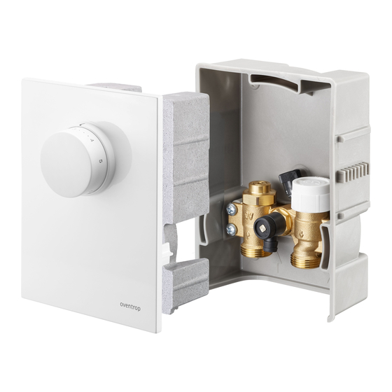
Le débit d'eau de chauffage est réparti en deux débits partiels, un débit à réglage thermosta- tique et un débit bypass. Le débit bypass sert Fig. 2: Configuration de l'« Unibox E BV » au réglage d'une charge calorifique de base. Le refroidissement complet de la surface chauf- fante est ainsi évité lors d'une fermeture du Équerre de fixation... -
Seite 44: Éléments De Manœuvre
Description technique Unibox E BV 3.4 Éléments de manœuvre Régler le bypass à l'aide de la poignée ma- nuelle. 3.4.1 Tête thermostatique AVIS Endommagement de la chape lié aux températures inadaptées f Respecter les consignes données par le fabricant de la chape. -
Seite 45: Données Techniques
Unibox E BV Accessoires et pièces de rechange 3.6 Données techniques Température 100°C de service La température de max. t s départ de l'instal- lation de surfaces chauffantes ne doit pas dépasser 55 °C (installation de chauffage de basse température). Pression de 10 bar service max. -
Seite 46: Montage
Montage Unibox E BV Stocker le produit dans les conditions sui- AVIS vantes : Dégâts matériels liés aux lubri- Plage de tem- -20°C à +60°C fiants pérature Des graisses et de l’huile peuvent en- Humidité rela- max. 95% dommager les joints. -
Seite 47: Montage De L'« Unibox E Bv
Unibox E BV Mise en service 6.2 Montage de l'« Unibox E BV » l'« Unibox E BV ». 3. Réaliser une dérivation partant de la Monter l'« Unibox E BV » de telle conduite aller de l'installation de chauffage manière que le fluide passe en bitube. premier par le robinet de l'« Unibox 4. Raccorder la conduite de dérivation à E BV » et par le circuit de surface l'« Unibox E BV ». Respecter le sens de chauffante ensuite. -
Seite 48: Mise En Chauffe
Service Unibox E BV 7.4 Capot avec tête faces chauffantes. thermostatique AVIS 1. Une fois les travaux de construction Endommagement de la chape terminés, enlever le capot de protection de lié aux températures inadaptées l'« Unibox E BV ». f Réaliser la mise en chauffe des 2. -
Seite 49: Maintenance
Unibox E BV Maintenance Maintenance Vérifier régulièrement le fonctionnement et l'étanchéité du produit et des points de raccordement dans le cadre de l'entretien de l'installation. 10. Démontage et traitement des déchets 10.1 Traitement des déchets AVIS Risque de pollution Une élimination non conforme (par ex. -
Seite 50: Annexe
Annexe Unibox E BV 11. Annexe 11.1 Questions fréquentes QUESTION RÉPONSE Quelle est la taille, en m² Chaque « Unibox E BV » peut être raccordé à environ 20 m² de d'une installation de surfaces surface. La longueur d'un tube de diamètre 17 mm ne doit pas chauffantes pouvant être rac- dépasser 100 m. -
Seite 51: Diagramme Des Pertes De Charge
Unibox E BV Annexe 11.2 Diagramme des pertes de charge Préréglage Débit [l/h] Fig. 11: Diagramme - Mécanisme de réglage avec un écart P de 2 K, préréglage du bypass 1,4 (25%) 102272480-V01.04.2020... - Seite 52 Annexe Unibox E BV Préréglage Débit [l/h] Fig. 12: Diagramme - Mécanisme de réglage avec un écart P de 2 K, préréglage du bypass 1,9 (50%) 102272480-V01.04.2020...
- Seite 53 Unibox E BV Annexe Préréglage Débit [l/h] Fig. 13: Diagramme - Mécanisme de réglage avec un écart P de 2 K, préréglage du bypass 2,3 (75%) 102272480-V01.04.2020...
- Seite 54 Annexe Unibox E BV Préréglage Débit [l/h] Fig. 14: Diagramme - Mécanisme de réglage avec un écart P de 2 K, bypass fermé 102272480-V01.04.2020...
- Seite 56 OVENTROP GmbH & Co. KG Paul-Oventrop-Straße 1 D-59939 Olsberg Telefon +49 (0) 29 62 82-0 Telefax +49 (0) 29 62 82-400 E-Mail mail@oventrop.de Internet www.oventrop.com 102272480 V01.04.2020...