RICOO SE2544 Montageanleitung
Fernbedienbare motorisierte wandhalterung für bildschirm
Verfügbare Sprachen
Verfügbare Sprachen
Quicklinks
Bitte überprüfen Sie VOR der Montage den Lochabstand zwischen den VESA-Befestigungslöchern an
!
Diese Wandhalterung unterstützt folgende Lochabstände:
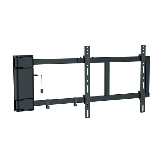
SE2544
Fernbedienbare motorisierte
Wandhalterung für Bildschirm
Horizontal / Waagerecht
Vertikal / Senkrecht
200x200
300x100
300x200
300x300
Ihrem Bildschirm!
VESA-Befestigungslöcher
Vertikal /
Senkrecht
Horizontal / Waagerecht
Bildschirm Rückseite
min. 200mm - max. 425mm
min. 200mm - max. 415mm
400x100
400x200
400x300
400x400
MONTAGEANLEITUNG
ACHTUNG: NIEMALS DAS MAXIMAL
ZULÄSSIGE BELASTUNGSGEWICHT
ÜBERSCHREITEN. MISSACHTUNG
KANN ZU SACHSCHÄDEN ODER
SCHWEREN VERLETZUNGEN FÜHREN!
40kg
(88lbs)
MAX
Deutsch
v.17.10
English

Verwandte Anleitungen für RICOO SE2544


Inhaltszusammenfassung für RICOO SE2544
- Seite 1 Senkrecht Horizontal / Waagerecht Bildschirm Rückseite Diese Wandhalterung unterstützt folgende Lochabstände: min. 200mm - max. 425mm Horizontal / Waagerecht min. 200mm - max. 415mm Vertikal / Senkrecht 200x200 400x100 40kg SE2544 300x100 400x200 (88lbs) 300x200 400x300 300x300 400x400 Deutsch English...
- Seite 2 Liebe Kundin, lieber Kunde, SE2544 wir freuen uns, dass Sie sich für ein Produkt der Marke "RICOO" entschieden haben Manchmal trotz aller Bemühungen unsererseits Ihnen ein qualitativ hochwertiges Produkt zu liefern, kann es vorkommen, dass einmal ein Zubehörteil fehlt oder ein Teil während des Transports beschädigt wird...
- Seite 3 Lieferumfang WICHTIG: Stellen Sie vor der Montage sicher, dass alle Teile welche hier aufgeführt sind, bei der Lieferung dabei sind. Sollten Teile fehlen oder defekt sein, kontaktieren Sie Ihren Händler. Schablone (x1) Kabelführungsclips (x2) Grundgerüst (x1) IR-Empfänger (x1) Stromadapter (x1) Montageschiene (x2) Fernbedienung (x1) Wasserwaage (x1)
- Seite 4 Die Schrauben und die Scheiben mit passendem Schraubenzieher entfernen. Der Auslegearm muss vor der Montage entsprechend der Bildschirm-Breite eingestellt werden. X = (B : 2) + 260mm ( B = komplette Breite des Bildschirms) X = (B : 2) + 260mm Nach der Einstellung alle Schrauben inkl.
- Seite 5 Für Montage an der Holzbalkenwand Montagevariante 1: Für Ausschwenkung von rechts 55mm 55mm (2.2") (2.2") Montagelöcher Wandplatte an Holzbalken mit Balkenfinder finden und die Montagelöcher bohren. die Wand ø 4.5mm markieren. anschrauben. (ø 3/16") Die Schraube so eindrehen, dass zwischen der √...
- Seite 6 Für Montage an der Holzbalkenwand Montagevariante 2: umgekehrt Für Ausschwenkung von links 55mm 55mm (2.2") (2.2") Montagelöcher Wandplatte an Holzbalken mit Balkenfinder finden und die Montagelöcher bohren. die Wand ø 4.5mm markieren. anschrauben. (ø 3/16") W-A(x1) Die Schraube so eindrehen, dass zwischen der √...
- Seite 7 Für Montage an der Massivbetonwand Montagevariante 1: Für Ausschwenkung von rechts 60mm 60mm (2.4") (2.4") Montagelöcher Montagelöcher Wandplatte an markieren. bohren. die Wand ø 10mm anschrauben. (ø 3/8") Achtung: Mitgelieferte Dübel sind nur für Massivbeton- wände geeignet! W-B(x5) W-A(x1) Die Schraube so eindrehen, dass zwischen der √...
- Seite 8 Für Montage an der Massivbetonwand Montagevariante 2: umgekehrt Für Ausschwenkung von links 60mm 60mm (2.4") (2.4") Montagelöcher Montagelöcher Wandplatte an markieren. bohren. die Wand ø 10mm anschrauben. (ø 3/8") Achtung: Mitgelieferte Dübel sind nur für Massivbeton- wände geeignet! W-B(x5) W-A(x1) Die Schraube so eindrehen, dass zwischen der √...
- Seite 9 Deutsch English...
- Seite 10 Zwei Schrauben an den Montageschienen entfernen. Die Schrauben für die spätere Montage bereit halten. Für Bildschirme mit flacher Rückseite Oberseite des TVs Deutsch English...
- Seite 11 Für Bildschirme mit gewölbter Rückseite Oberseite des TVs oder oder oder oder oder Beachten: Wählen Sie die zu Ihrem TV passenden Schrauben, Unterlegscheiben und falls erforderlich die Abstandshalter. · Montieren Sie die Montageschienen so nah wie möglich zur Mitte des TV-Gerätes. ·...
- Seite 12 Ziehen Sie zwei Schrauben mit einem passenden Schraubendreher nach, um die Halterung zu sichern. Um die Neigung (wegen dem TV-Gewicht) auszugleichen, können Sie die oberen Schrauben an den Montageschienen entsprechend einstellen. Deutsch English...
- Seite 13 Kabelführung oder • Schließen Sie die Kabel an Ihrem Fernseher an und führen Sie die Kabel durch die Kabelführungsclips. ACHTUNG: • Auf genügend Kabellockerung achten, damit das Schwenken der Halterung nicht beinträchtigt wird. Deutsch English...
- Seite 14 Montage des IR-Empfängers Bitte die Abdeckung der Elektronik nicht öffnen! Stromleitung nicht anschließen, bis das Produkt einsatzbereit ist! Aufkleberpapier ablösen. IR-Empfänger auf der gewünschten Position aufkleben. Stellen Sie sicher, dass das IR-Signal von keinen Hindernissen beeinträchtigt wird. Betriebsanleitung der Fernbedienung Fernbedienung Tastenbefehle.
- Seite 15 Betriebsanleitung der Fernbedienung Tastenfunktion-Anleitung "Stopp" Taste "Nach links" Taste. Drücken Sie die Taste , die Halterung wird nach links geschwenkt bis die Taste gedrückt wird oder die Halterung 90° (+/-5°) Schwenkung erreicht hat. "Nach rechts" Taste. Drücken Sie die Taste , die Halterung wird nach rechts geschwenkt bis die Taste gedrückt wird oder die Halterung 0°...
- Seite 16 Betriebsanleitung der Fernbedienung Anlern-Modus Bedienungsanleitung 2/2 Anlern-Modus Anleitung. Als Beispiel mit der Taste Drücken und halten Sie die Taste für 5 Sekunden bis die LED auf der originalen Fernbedienung der Halterung Schritt 1: dauerhaft leuchtet, drücken Sie anschließend die Taste .