Lenze i900 Montage- Und Einschaltanleitung
Servo-inverter i950-cabinet 0.55 ... 75 kw

Verwandte Anleitungen für Lenze i900


Inhaltszusammenfassung für Lenze i900
- Seite 1 Montage- und Einschaltanleitung | Mounting and switch-on instructions i900 Servo-Inverter i950-Cabinet 0.55 ... 75 kW i900 Servo-Inverter i950-Cabinet 0.55 ... 75 kW...
-
Seite 3: Inhaltsverzeichnis
Inhalt Inhalt Über dieses Dokument Dokumentbeschreibung Weiterführende Dokumente Schreibweisen und Konventionen Sicherheitshinweise Grundlegende Sicherheitshinweise Bestimmungsgemäße Verwendung Handhabung Restgefahren Produktinformation Identifizierung der Produkte Ausstattung Mechanische Installation Abmessungen Elektrische Installation Wichtige Hinweise Netzanschluss 3-phasiger Netzanschluss 400 V Anschlusspläne Absicherungsdaten Klemmendaten 3-phasiger Netzanschluss 480 V Absicherungsdaten Klemmendaten Anschluss an das IT-Netz... - Seite 4 Inhalt Technische Daten Normen und Einsatzbedingungen Konformitäten/Approbationen Personenschutz und Geräteschutz Angaben zur EMV Motoranschluss Umweltbedingungen Netzbedingungen 3-phasiger Netzanschluss 400 V Bemessungsdaten 3-phasiger Netzanschluss 480 V Bemessungsdaten...
-
Seite 5: Über Dieses Dokument
Software z. B. Engineering Tools Feldbus-Gerätebeschreibungen AKB-Artikel Application Knowledge Base CAD-Daten Exporte in verschieden Formaten EPLAN Makros Projektierung, Dokumentation und Verwaltung von Projekten • EPLAN P8-Makros Informationen und Hilfsmittel rund um die Lenze-Produkte finden Sie im Internet: http://www.lenze.com à Download... -
Seite 6: Schreibweisen Und Konventionen
Über dieses Dokument Schreibweisen und Konventionen Schreibweisen und Konventionen Zur Unterscheidung verschiedener Arten von Informationen werden in diesem Dokument Konventionen ver- wendet. Zahlenschreibweise Dezimaltrennzeichen Punkt Es wird generell der Dezimalpunkt verwendet. Beispiel: 1 234.56 Warnhinweise UL-Warnhinweise Werden in englischer und französischer Sprache verwendet. UR-Warnhinweise Textauszeichnung Programme... -
Seite 7: Sicherheitshinweise
Sicherheitshinweise Grundlegende Sicherheitshinweise Sicherheitshinweise Wenn Sie die folgenden grundlegenden Sicherheitsmaßnahmen und Sicherheitshinweise missachten, kann dies zu schweren Personenschäden und Sachschäden führen! Alle Vorgaben der beiliegenden und zugehörigen Dokumentation beachten. Dies ist Voraussetzung für einen sicheren und störungsfreien Betrieb sowie für das Erreichen der angegebenen Produkteigenschaften. Beachten Sie die spezifischen Sicherheitshinweise in den anderen Abschnitten! Grundlegende Sicherheitshinweise Personal... -
Seite 8: Restgefahren
Sicherheitshinweise Restgefahren Restgefahren Auch wenn gegebene Hinweise beachtet und Schutzmaßnahmen angewendet werden, können Restrisiken verbleiben. Die genannten Restgefahren muss der Anwender in der Risikobeurteilung für seine Maschine/Anlage berück- sichtigen. Nichtbeachtung kann zu schweren Personenschäden und Sachschäden führen! Produkt Beachten Sie die Warnschilder auf dem Produkt! Symbol Beschreibung Elektrostatisch gefährdete Bauelemente:... -
Seite 9: Produktinformation
In Tabellen werden die ersten 9 Stellen des jeweiligen Produktcodes verwendet, um die Produkte zu identifi- zieren: Produktcode I 9 5 A E □□□ F 1 □ □ □ 0 □□□□ Produktart Inverter Produktfamilie i900 Produkt i950 Produktgeneration Generation 1 Montageart Schaltschrankmontage Bemessungsleistung [W] 0.55 kW... -
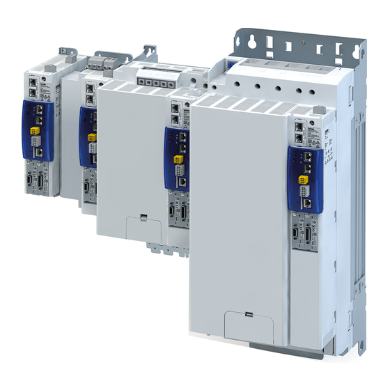
Seite 10: Ausstattung
Produktinformation Ausstattung Ausstattung Beispiel für 0.55 kW ... 4 kW PE-Anschluss Netzanschluss X100 IT-Schraube Schirmauflage Steueranschlüsse 24-V-Versorgung X5 Option Für Steuerelektronik Netzwerk X2xx Status- s Netzwerk Option Status- s Inverter Systembus EtherCAT IN X236 Systembus EtherCAT OUT X237 Anschluss Sicherheitstechnik X1 Option Safe Torque Off (STO) Steuerklemmen X3 SD-Karte... - Seite 11 Produktinformation Ausstattung Beispiel für 7.5 kW ... 15 kW Netzanschluss X100 Anschluss -Bus X101 Stecker nicht im Lieferumfang PE-Anschluss 24-V-Versorgung X5 Schirmauflage Steueranschlüsse Für Steuerelektronik Option Status- s Netzwerk Netzwerk X2xx Option Systembus EtherCAT IN X236 Status- s Inverter Systembus EtherCAT OUT X237 Anschluss Sicherheitstechnik X1 Option Safe Torque Off (STO) Steuerklemmen X3...
- Seite 12 Produktinformation Ausstattung Beispiel für 22 kW PE-Anschluss Anschluss Netz/DC-Bus X100 IT-Schraube Schirmauflage Steueranschlüsse Option 24-V-Versorgung X5 Für Steuerelektronik Netzwerk X2xx Status- s Netzwerk Option Systembus EtherCAT IN X236 Status- s Inverter Systembus EtherCAT OUT X237 Anschluss Sicherheitstechnik X1 Option Safe Torque Off (STO) Steuerklemmen X3 SD-Karte Ethernet NRT-Schnittstelle X16...
- Seite 13 Produktinformation Ausstattung Beispiel für 30 kW ... 45 kW Anschluss Netz/DC-Bus X100 PE-Anschluss Schirmauflage Steueranschlüsse IT-Schraube Option 24-V-Versorgung X5 Für Steuerelektronik Netzwerk X2xx Status- Status- s Netzwerk s Netzwerk Status- Status- s Netzwerk s Netzwerk Option Systembus EtherCAT IN X236 Status- s Inverter Systembus EtherCAT OUT X237...
- Seite 14 Produktinformation Ausstattung Beispiel für 55 kW ... 75 kW Anschluss Netz/DC-Bus X100 PE-Anschluss Schirmauflage Steueranschlüsse IT-Schraube Option 24-V-Versorgung X5 Für Steuerelektronik Netzwerk X2xx Status- s Netzwerk Option Systembus EtherCAT IN X236 Status- s Inverter Systembus EtherCAT OUT X237 Steuerklemmen X3 Anschluss Sicherheitstechnik X1 SD-Karte Option Safe Torque Off (STO)
-
Seite 15: Mechanische Installation
Mechanische Installation Abmessungen Mechanische Installation Abmessungen 0.55 kW ... 4 kW Die Abmessungen in mm gelten für: 0.55 kW I95AE155F 0.75 kW I95AE175F 2.2 kW I95AE222F 4 kW I95AE240F... - Seite 16 Mechanische Installation Abmessungen 7.5 kW ... 15 kW Die Abmessungen in mm gelten für: 7.5 kW I95AE275F 11 kW I95AE311F 15 kW I95AE315F...
- Seite 17 Mechanische Installation Abmessungen 22 kW Die Abmessungen in mm gelten für: 22 kW I95AE322F...
- Seite 18 Mechanische Installation Abmessungen 30 kW ... 45 kW Die Abmessungen in mm gelten für: 30 kW I95AE330F 45 kW I95AE345F...
- Seite 19 Mechanische Installation Abmessungen 55 kW ... 75 kW Die Abmessungen in mm gelten für: 55 kW I95AE355F 75 kW I95AE375F...
-
Seite 20: Elektrische Installation
Elektrische Installation Wichtige Hinweise Elektrische Installation Wichtige Hinweise GEFAHR! Gefährliche elektrische Spannung Mögliche Folge: Tod oder schwere Verletzungen ▶ Alle Arbeiten am Inverter nur im spannungslosen Zustand durchführen. ▶ Nach dem Abschalten der Netzspannung mindestens 3 Minuten warten, bevor Sie mit den Arbeiten beginnen. - Seite 21 ▶ Les variateurs doivent être utilisés avec inductance de ligne raccordée en série avec alimentation secteur CA, toutes avec une puissance assignée mini de 480 V. ▶ Se reporter au tableau ci-dessous pour connaître les désignations de type Lenze. Inverter...
- Seite 22 Elektrische Installation Wichtige Hinweise WARNUNG! ▶ UL marking ▶ Suitable for motor group installation. ▶ 0.55 kW ... 30 kW devices on a circuit capable of delivering not more than 5k rms symmetrical amperes, 480 V maximum when protected by fuses or circuit breakers. Ratings see table below. ▶...
-
Seite 23: Netzanschluss
Elektrische Installation Netzanschluss 3-phasiger Netzanschluss 400 V Netzanschluss 3-phasiger Netzanschluss 400 V Anschlusspläne Der Anschlussplan ist gültig für die Inverter I95AExxxF. 3/N/PE AC 400 V 3/PE AC 340 V ... 528 V 45 Hz ... 65 Hz DC 24 V SELV/PELV (+19.2 V ... -
Seite 24: Absicherungsdaten
Elektrische Installation Netzanschluss 3-phasiger Netzanschluss 400 V Absicherungsdaten Sicherungsdaten Inverter I95AE155F I95AE155F I95AE175F I95AE175F I95AE222F I95AE222F Leitungsinstallation nach EN 60204-1 Verlegeart ohne Netzdrossel Schmelzsicherung Charakteristik gG/gL oder gRL Max. Bemessungsstrom Sicherungsautomat Charakteristik Max. Bemessungsstrom mit Netzdrossel Schmelzsicherung Charakteristik gG/gL oder gRL Max. - Seite 25 Elektrische Installation Netzanschluss 3-phasiger Netzanschluss 400 V Sicherungsdaten Inverter I95AE315F I95AE315F I95AE322F I95AE322F I95AE330F I95AE330F Leitungsinstallation nach EN 60204-1 Verlegeart ohne Netzdrossel Schmelzsicherung Charakteristik Max. Bemessungsstrom Sicherungsautomat Charakteristik Max. Bemessungsstrom mit Netzdrossel Schmelzsicherung Charakteristik gG/gL oder gRL Max. Bemessungsstrom Sicherungsautomat Charakteristik Max.
- Seite 26 Elektrische Installation Netzanschluss 3-phasiger Netzanschluss 400 V Sicherungsdaten Inverter I95AE155F I95AE175F I95AE222F I95AE240F I95AE275F I95AE311F Leitungsinstallation nach US National Electrical Code NFPA 70 / Canadian Electrical Code C22.1 Verlegeart ohne Netzdrossel Schmelzsicherung Charakteristik all acc. to UL 248 / Class CC, J, T Max.
-
Seite 27: Klemmendaten
Elektrische Installation Netzanschluss 3-phasiger Netzanschluss 400 V Klemmendaten Netzanschluss Inverter I95AE155F I95AE175F I95AE222F I95AE240F I95AE275F I95AE311F Anschluss X100 Anschlusstyp steckbare Schraubklemme Max. Leitungsquerschnitt mm² Max. Leitungsquerschnitt Abisolierlänge Abisolierlänge inch 0.32 0.32 0.32 0.32 0.55 0.55 Anziehdrehmoment Anziehdrehmoment lb-in Benötigtes Werkzeug 0.5 x 3.0 0.8 x 4.0 Netzanschluss... - Seite 28 Elektrische Installation Netzanschluss 3-phasiger Netzanschluss 400 V Motoranschluss Inverter I95AE155F I95AE175F I95AE222F I95AE240F I95AE275F I95AE311F Anschluss X105 Anschlusstyp steckbare Schraubklemme Max. Leitungsquerschnitt mm² Max. Leitungsquerschnitt Abisolierlänge Abisolierlänge inch 0.32 0.32 0.32 0.32 0.55 0.55 Anziehdrehmoment Anziehdrehmoment lb-in Benötigtes Werkzeug 0.5 x 3.0 0.8 x 4.0 Motoranschluss Inverter...
-
Seite 29: 3-Phasiger Netzanschluss 480 V
Elektrische Installation Netzanschluss 3-phasiger Netzanschluss 480 V 3-phasiger Netzanschluss 480 V Absicherungsdaten Sicherungsdaten Inverter I95AE155F I95AE155F I95AE175F I95AE175F I95AE222F I95AE222F Leitungsinstallation nach EN 60204-1 Verlegeart ohne Netzdrossel Schmelzsicherung Charakteristik gG/gL oder gRL Max. Bemessungsstrom Sicherungsautomat Charakteristik Max. Bemessungsstrom mit Netzdrossel Schmelzsicherung Charakteristik gG/gL oder gRL... - Seite 30 Elektrische Installation Netzanschluss 3-phasiger Netzanschluss 480 V Sicherungsdaten Inverter I95AE315F I95AE315F I95AE322F I95AE322F I95AE330F I95AE330F Leitungsinstallation nach EN 60204-1 Verlegeart ohne Netzdrossel Schmelzsicherung Charakteristik gG/gL oder gRL Max. Bemessungsstrom Sicherungsautomat Charakteristik Max. Bemessungsstrom mit Netzdrossel Schmelzsicherung Charakteristik gG/gL oder gRL Max.
- Seite 31 Elektrische Installation Netzanschluss 3-phasiger Netzanschluss 480 V Sicherungsdaten Inverter I95AE155F I95AE175F I95AE222F I95AE240F I95AE275F I95AE311F Leitungsinstallation nach US National Electrical Code NFPA 70 / Canadian Electrical Code C22.1 Verlegeart ohne Netzdrossel Schmelzsicherung Charakteristik all acc. to UL 248 / Class CC, J, T Max.
-
Seite 32: Klemmendaten
Elektrische Installation Netzanschluss 3-phasiger Netzanschluss 480 V Klemmendaten Netzanschluss Inverter I95AE155F I95AE175F I95AE222F I95AE240F I95AE275F I95AE311F Anschluss X100 Anschlusstyp steckbare Schraubklemme Max. Leitungsquerschnitt mm² Max. Leitungsquerschnitt Abisolierlänge Abisolierlänge inch 0.32 0.32 0.32 0.32 0.55 0.55 Anziehdrehmoment Anziehdrehmoment lb-in Benötigtes Werkzeug 0.5 x 3.0 0.8 x 4.0 Netzanschluss... - Seite 33 Elektrische Installation Netzanschluss 3-phasiger Netzanschluss 480 V Motoranschluss Inverter I95AE155F I95AE175F I95AE222F I95AE240F I95AE275F I95AE311F Anschluss X105 Anschlusstyp steckbare Schraubklemme Max. Leitungsquerschnitt mm² Max. Leitungsquerschnitt Abisolierlänge Abisolierlänge inch 0.32 0.32 0.32 0.32 0.55 0.55 Anziehdrehmoment Anziehdrehmoment lb-in Benötigtes Werkzeug 0.5 x 3.0 0.8 x 4.0 Motoranschluss Inverter...
-
Seite 34: Anschluss An Das It-Netz
Elektrische Installation Anschluss an das IT-Netz Anschluss an das IT-Netz HINWEIS Interne Bauteile haben Erdpotenzial, wenn die IT-Schrauben nicht entfernt werden. Folge: Die Überwachungseinrichtungen des IT-Netzes sprechen an. ▶ Vor dem Anschluss an ein IT-Netz unbedingt die IT-Schrauben entfernen. I95AE155F, I95AE175F, I95AE222F, I95AE240F I95AE275F, I95AE311F, I95AE315F TX10 TX10... - Seite 35 Elektrische Installation Anschluss an das IT-Netz I95AE322F...
- Seite 36 Elektrische Installation Anschluss an das IT-Netz I95AE330F, I95AE345F I95AE355F, I95AE375F...
-
Seite 37: Steueranschlüsse
Elektrische Installation Steueranschlüsse Steueranschlüsse Beschreibung des Anschlus- PTC-Eingang Anschluss Motor- 24-V-Versorgung 24-V-Versorgung bremse Motorbremse Steuerelektronik Anschluss X109 X106 X107 Anschlusstyp steckbare Schraub- steckbare Feder- steckbare Federkraft-Doppelklemme klemme kraftklemme Max. Leitungsquerschnitt mm² Max. Leitungsquerschnitt Abisolierlänge Abisolierlänge inch 0.24 0.35 0.39 0.39 Anziehdrehmoment Anziehdrehmoment lb-in... -
Seite 38: Systembus Ethercat
Elektrische Installation Systembus EtherCAT Systembus EtherCAT LED "RUN" Blinkmuster Zustand Bedeutung Versorgungsspannung nicht vorhanden. Initialisation (Init) Netzwerk nicht aktiv Kein Datentransfer Pre-Operational (Pre-Op) Zugriff möglich Kein Prozessdatentransfer blinkt 1:1 Safe-Operational (Safe-Op) Zustände der sicheren Eingänge sind les- bar. blinkt langsam 3:1 Operational (Op) Datentransfer in Aktion LED "L/A"... -
Seite 39: Netzwerke
Elektrische Installation Netzwerke PROFINET Netzwerke PROFINET Statusanzeigen an den RJ45-Buchsen Die LEDs an den RJ45-Buchsen zeigen den Verbindungsstatus zum Netzwerk an. LED "Link" Zustand/Bedeutung (grün) Keine Verbindung zum Netzwerk. Physikalische Verbindung zum Netzwerk ist vorhanden. LED "Activity" Zustand/Bedeutung (gelb) Kein Datentransfer. Daten werden über das Netzwerk ausgetauscht. - Seite 40 Elektrische Installation Funktionale Sicherheit PROFINET Funktionale Sicherheit GEFAHR! Bei unsachgemäßer Installation der Sicherheitstechnik können Antriebe unkontrolliert anlaufen. Mögliche Folge: Tod oder schwere Verletzungen ▶ Nur qualifiziertes Personal darf Sicherheitstechnik installieren und in Betrieb nehmen. ▶ Alle Steuerungskomponenten (Schalter, Relais, SPS, ...) müssen die Anforderungen der EN ISO 13849−1 und der EN ISO 13849−2 erfüllen.
- Seite 41 Elektrische Installation Funktionale Sicherheit PROFINET HINWEIS Überspannung Zerstörung der Safety-Komponente ▶ Die maximale Spannung (maximum rated) an den Safety-Eingängen beträgt 30 V DC. Der Anwender muss Vorkehrungen treffen, damit diese Spannung nicht überschritten wird.
-
Seite 42: Funktionale Sicherheit Sicher Abgeschaltetes Moment (Sto)
Elektrische Installation Funktionale Sicherheit Sicher abgeschaltetes Moment (STO) Sicher abgeschaltetes Moment (STO) Passive Sensoren SS1c/SS1-t undelayed delayed +24 V DC 24 V SELV/PELV Passiver Sensor Passiver Sensor Passiver Sensor Sicherheits-Schaltgerät Sicherheits-Schaltgerät mit verzögerten Kontakten Not-Halt (STO) Not-Halt (SS1c/SS1-t) undelayed delayed Reset Reset Sicherheits-Schaltgerät... -
Seite 43: Aktive Sensoren
Elektrische Installation Funktionale Sicherheit Sicher abgeschaltetes Moment (STO) Aktive Sensoren Aktiver Sensor - Beispiel Lichtgitter Beschreibung des Anschlus- Safety STO Anschluss Anschlusstyp steckbare Federkraftklemme Max. Leitungsquerschnitt mm² Max. Leitungsquerschnitt Abisolierlänge Abisolierlänge inch 0.35 Anziehdrehmoment Anziehdrehmoment lb-in Benötigtes Werkzeug 0.4 x 2.5... -
Seite 44: Inbetriebnahme
Inbetriebnahme Wichtige Hinweise Inbetriebnahme Wichtige Hinweise WARNUNG! Fehlerhafte Verdrahtung kann zu unerwarteten Zuständen während der Inbetriebnahme führen. Mögliche Folge: Tod, schwere Verletzungen oder Sachschäden Prüfen Sie vor dem Einschalten der Netzspannung: ▶ Ist die Verdrahtung vollständig und richtig ausgeführt? ▶ Gibt es keine Kurzschlüsse und Erdschlüsse? ▶... -
Seite 45: Sicherheitsfunktionen
Sicherheitsfunktionen Sicher abgeschaltetes Moment (STO) Sicherheitsfunktionen Sicher abgeschaltetes Moment (STO) GEFAHR! Automatischer Wiederanlauf, wenn die Anforderung der Sicherheitsfunktion aufgehoben wird. Mögliche Folge: Tod oder schwere Verletzungen ▶ Sie müssen durch externe Maßnahmen nach EN ISO 13849−1 dafür sorgen, dass der Antrieb erst nach einer Bestätigung wieder anläuft. -
Seite 46: Technische Daten
Technische Daten Normen und Einsatzbedingungen Konformitäten/Approbationen Technische Daten Normen und Einsatzbedingungen Konformitäten/Approbationen Konformität 2006/42/EC Maschinenrichtlinie 2014/30/EU EMV-Richtlinie (Bezug: CE-typisches Antriebssystem) RoHS 2011/65/EU Beschränkung der Verwendung bestimmter gefährlicher Stoffe in Elektro- und Elektronikgeräten Approbation UL 61800-5-1 für USA und Kanada (Anforderungen der CSA 22.2 No. 274) UL 61800-5-1 File No. -
Seite 47: Motoranschluss
Technische Daten Normen und Einsatzbedingungen Motoranschluss Motoranschluss Anforderungen an die geschirmte Motorleitung Kapazitätsbelag C-Ader-Ader/C-Ader-Schirm < 75/150 ≤ 2.5 mm² / AWG 14 pF/m C-Ader-Ader/C-Ader-Schirm < 150/300 ≥ 4 mm² / AWG 12 pF/m Spannungsfestigkeit Uo/U = 0.6/1.0 kV Uo = Effektivwert Außenleiter zu PE Uo/U = 0.6/1.0 kV U = Effektivwert Außenleiter zu Außenleiter U ≥... -
Seite 48: 3-Phasiger Netzanschluss 400 V
Technische Daten 3-phasiger Netzanschluss 400 V Bemessungsdaten 3-phasiger Netzanschluss 400 V Bemessungsdaten Inverter I95AE155F I95AE175F I95AE222F I95AE240F I95AE275F I95AE311F Bemessungsleistung 0.55 0.75 Bemessungsleistung 0.75 Netzspannungsbereich 3/PE AC 340 V ... 528 V, 45 Hz ... 65 Hz Ausgangsspannung 3 AC 0-400/480 V Netz-Bemessungsstrom ohne Netzdrossel 12.5... - Seite 49 Technische Daten 3-phasiger Netzanschluss 400 V Bemessungsdaten Inverter I95AE315F I95AE322F I95AE330F I95AE345F I95AE355F I95AE375F Bemessungsleistung Bemessungsleistung Netzspannungsbereich 3/PE AC 340 V ... 528 V, 45 Hz ... 65 Hz Ausgangsspannung 3 AC 0-400/480 V Netz-Bemessungsstrom ohne Netzdrossel N, AC mit Netzdrossel 28.8 54.9 N, AC...
-
Seite 50: 3-Phasiger Netzanschluss 480 V
Technische Daten 3-phasiger Netzanschluss 480 V Bemessungsdaten 3-phasiger Netzanschluss 480 V Bemessungsdaten Inverter I95AE155F I95AE175F I95AE222F I95AE240F I95AE275F I95AE311F Bemessungsleistung 0.55 0.75 Bemessungsleistung 0.75 Netzspannungsbereich 3/PE AC 340 V ... 528 V, 45 Hz ... 65 Hz Ausgangsspannung 3 AC 0-400/480 V Netz-Bemessungsstrom ohne Netzdrossel 10.5... - Seite 51 Technische Daten 3-phasiger Netzanschluss 480 V Bemessungsdaten Inverter I95AE315F I95AE322F I95AE330F I95AE345F I95AE355F I95AE375F Bemessungsleistung Bemessungsleistung Netzspannungsbereich 3/PE AC 340 V ... 528 V, 45 Hz ... 65 Hz Ausgangsspannung 3 AC 0-400/480 V Netz-Bemessungsstrom ohne Netzdrossel 47.4 N, AC mit Netzdrossel 35.3 45.7...
- Seite 104 © 11/2017 | 13544348 | 1.0 Lenze Automation GmbH Ö Postfach 10 13 52, D-31763 Hameln Hans-Lenze-Str. 1, D-31855 Aerzen Germany HR Hannover B 205381 +49 5154 82-0 Ü +49 5154 82-2800 Ø lenze@lenze.com Ù www.lenze.com Ú Lenze Service GmbH Û...