Riello RS 300/M BLU type 859 T Installations-, Bedienungs- Und Wartungsanleitung
Vorschau ausblenden
Andere Handbücher für RS 300/M BLU type 859 T:
- Installations-, bedienungs- und wartungsanleitung (68 Seiten) ,
- Installations-, bedienungs- und wartungsanleitung (60 Seiten)
Inhaltsverzeichnis
Werbung
Quicklinks
Istruzioni per installazione, uso e manuntenzione
Installations-, Bedienungs- und Wartungsanleitung
Installation, use and maintenance instructions
Instructions pour l'installation, l'utilisation et l'entretien
Bruciatori di gas ad aria soffiata
I
Gas- Gebläsebrenner
D
Forced draught gas burners
GB
Brûleurs gaz à air soufflé
F
Funzionamento modulante
Modulierender Betrieb
Modulating operation
Fonctionnement modulant
CODICE - CODE
20009386
20008428
20008311
20008404
MODELLO - MODELL
MODEL - MODELE
RS 300/M BLU
RS 300/M BLU
RS 400/M BLU
RS 400/M BLU
TIPO - TYP
TYPE - TYPE
859 T
859 T80
860 T
860 T80
20008402 (9) - 01/2016
Werbung
Inhaltsverzeichnis

Verwandte Anleitungen für Riello RS 300/M BLU type 859 T


Inhaltszusammenfassung für Riello RS 300/M BLU type 859 T
- Seite 1 Istruzioni per installazione, uso e manuntenzione Installations-, Bedienungs- und Wartungsanleitung Installation, use and maintenance instructions Instructions pour l'installation, l'utilisation et l'entretien Bruciatori di gas ad aria soffiata Gas- Gebläsebrenner Forced draught gas burners Brûleurs gaz à air soufflé Funzionamento modulante Modulierender Betrieb Modulating operation Fonctionnement modulant...
- Seite 3 La qualità viene garantita mediante un sistema di qualità e management certificato secondo UNI EN ISO 9001. Legnago, 01.12.2015 Direttore Generale Direttore Ricerca e Sviluppo RIELLO S.p.A. - Direzione Bruciatori RIELLO S.p.A. - Direzione Bruciatori Ing. U. Ferretti Ing. F. Comencini Konformitätserklärung gemäß...
- Seite 4 The quality is guaranteed by a quality and management system certified in accordance with UNI EN ISO 9001. Legnago, 01.12.2015 Executive General Manager Research & Development Director RIELLO S.p.A. - Burner Department RIELLO S.p.A. - Burner Department Mr. U. Ferretti Mr. F. Comencini Déclaration de conformité...
-
Seite 5: Inhaltsverzeichnis
INDICE INHALT Dati tecnici ........pagina 4 Technische Angaben . -
Seite 6: Dati Tecnici
DATI TECNICI Modello RS 300/M BLU RS 300/M BLU RS 400/M BLU RS 400/M BLU Tipo 859 T 859 T80 860 T 860 T80 Massima 1350 ÷ 3800 1350 ÷ 3800 1830 ÷ 4590 1830 ÷ 4590 Potenza Minima Combustibile Gas naturale: G20 (metano) - G21 - G22 - G23 - G25 Pressione gas alla potenza Max. -
Seite 7: Elenco Modelli Disponibili
DESIGNAZIONE BRUCIATORI SERIE RS Serie : R Combustibile : Gas naturale Gasolio Gasolio / Metano Nafta Grandezza Regolazione : Camma elettronica Camma elettronica e velocità variabile (con Inverter) Camma meccanica Valvola proporzionale aria/gas Emissione : Classe 1 EN267 - EN676 Classe 2 EN267 - EN676 Classe 3 EN267 - EN676 Classe 2 EN267... -
Seite 8: Technische Angaben
TECHNISCHE ANGABEN Modell RS 300/M BLU RS 300/M BLU RS 400/M BLU RS 400/M BLU 859 T 859 T80 860 T 860 T80 Max. 1350 ÷ 3800 1350 ÷ 3800 1830 ÷ 4590 1830 ÷ 4590 Leistung Min. Brennstoff Erdgas: G20 (Methangas) - G21 - G22 - G23 - G25 Gasdruck bei Höchstleistung. -
Seite 9: Verzeinis Der Modelle
BEZEICHNUNG DER BRENNER DER SERIE RS Serie : R Brennstoff : Erdgas Heizöl EL Zweistoffbrenner Heizöl / Erdgas Erdöl Baugröße Einstellung : Elektronischer Nocken Elektronischer Nocken und variable Geschwindigkeit (mit Inverter) Mechanischer Nocken Luft/Gas Proportionalventil Emission : Klasse 1 EN267 - EN676 Klasse 2 EN267 - EN676 Klasse 3 EN267 - EN676 Klasse 2 EN267... -
Seite 10: Technical Data
TECHNICAL DATA Model RS 300/M BLU RS 300/M BLU RS 400/M BLU RS 400/M BLU Type 859 T 859 T80 860 T 856 T80 max. 1350 - 3800 1350 - 3800 1830 - 4590 1830 - 4590 Output min. Fuel Natural gas: G20 (methane) - G21 - G22 - G23 - G25 Gas pressure at maximum delivery. -
Seite 11: List Of Available Models
DESIGNATION OF BURNER SERIES RS Series : R Fuel : Natural gas Light oil Light oil / Methane Heavy oil Size Setting : Electronic cam Variable speed (with Inverter) Mechanical cam Air/gas proportioning valve Class 1 EN267 - EN676 Emission : Class 2 EN267 - EN676 Class 3 EN267 - EN676 Class 2 EN267... -
Seite 12: Données Techniques
DONNÉES TECHNIQUES Modele RS 300/M BLU RS 300/M BLU RS 400/M BLU RS 400/M BLU Type 859 T 859 T80 860 T 856 T80 Max. 1350 ÷ 3800 1350 ÷ 3800 1830 ÷ 4590 1830 ÷ 4590 Puissance Min. Combustible Gaz naturel: G20 (méthano) - G21 - G22 - G23 - G25 Pression du gaz à... -
Seite 13: Modèles Disponibles
DESIGNATION BRULEURS SERIE RS Série : R Combustible : Gas naturel Fioul Fioul / Méthano Fioul Dimension Régulation : Came électronique Came électronique et moteur à fréquence variable (avec Variateur de fréquence) Came mécanique Soupape proportionnelle air/ gaz Classe 1 EN267 - EN676 Émission : Classe 2 EN267 - EN676 Classe 3 EN267 - EN676... -
Seite 14: Descrizione Bruciatore
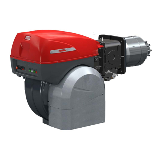
DESCRIZIONE BRUCIATORE (A) 1 Anelli di sollevamento 2 Girante 3 Motore ventilatore 4 Servomotore 5 Presa di pressione gas testa di combustione 6 Testa di combustione 7 Elettrodo di accensione 8 Disco di stabilità fiamma 9 Cofano quadro elettrico 10 Cerniera per apertura bruciatore 11 Ingresso aria ventilatore 12 Manicotto 13 Schermo per fissaggio alla caldaia... -
Seite 15: Burner Description
BRENNERBESCHREIBUNG (A) BURNER DESCRIPTION (A) DESCRIPTION BRULEUR (A) 1 Heberinge 1 Lifting eyebolts 1 Anneaux de soulèvement 2 Gebläserad 2 Fan 2 Turbine 3 Gebläsemotor 3 Fan motor 3 Moteur ventilateur 4 Stellantrieb 4 Servomotor 4 Servomoteur 5 Gasdruckentnahmestelle 5 Gas pressure test point 5 Prise de pression gaz 6 Flammkopf 6 Combustion head... -
Seite 16: Peso
PESO (A) Il peso del bruciatore completo di imballo è indi- cato nella tabella (A). RS 300/M BLU CORREDO RS 400/M BLU 1 Guarnizione per adattatore rampa gas 8 - Viti per fissare l’adattatore rampa gas: M 16 x 70 1 - Schermo termico 4 - Viti per fissare la flangia del bruciatore alla caldaia: M 18 x 60... -
Seite 17: Weight
GEWICHT (A) WEIGHT (A) POIDS (A) Das Gesamtgewicht des Brenners einschließ- The weight of the burner complete with packag- Le poids du brûleur avec son emballage est lich Verpackung wird aus Tabelle (A) ersichtlich. ing is indicated in Table (A). indiqué... -
Seite 18: Campi Di Lavoro
CAMPI DI LAVORO (A) La POTENZA MASSIMA va scelta entro l'area tratteggiata del diagramma. La POTENZA MINIMA non deve essere inferi- ore al limite minimo del diagramma: RS 300/M BLU = 500 kW RS 400/M BLU = 950 kW Attenzione: il CAMPO DI LAVORO è stato ricavato alla temperatura ambi- ente di 20 °C, alla pressione baromet- rica di 1013 mbar (circa 0 m s.l.m.) e... -
Seite 19: Firing Rates
REGELBEREICHE (A) FIRING RATES (A) PLAGES DE PUISSANCE (A) MAXIMUM OUTPUT must be selected in the La PUISSANCE MAXIMUM doit être choisie Die HÖCHSTLEISTUNG wird innerhalb der hatched area of the diagram. dans la zone hachurée du diagramme. schraffierten Zone im Diagramm gewählt. MINIMUM OUTPUT must not be lower than the La PUISSANCE MINIMUM ne doit pas être Die MINDESTLEISTUNG soll nicht niedriger... -
Seite 20: Installazione
INSTALLAZIONE RIMOZIONE VITI BLOCCO DELL’OTTURATORE Prima di montare il bruciatore sulla cal- daia rimuovere le viti e i dadi 1)-2)(D). RS 300/M BLU M 18 Sostituirli con le viti 3) M12 x25 fornite a RS 400/M BLU M 18 corredo. PIASTRA CALDAIA (A) Forare la piastra di chiusura della camera di combustione come in (A). -
Seite 21: Installation
INSTALLATION INSTALLATION INSTALLATION ENTFERNEN DER SPERRSCHRAU- REMOVAL LOCKING RETRAIT DES VIS DE BLOCAGE DE BEN DES SCHIEBERS SCREWS FROM THE SHUTTER L’OBTURATEUR Vor der Montage des Brenners am Kes- Remove the screws and the nuts 1)- Avant de monter le brûleur sur la chau- sel müssen die Schrauben und Muttern 2)(D), before installing the burner on the dière, retirer les vis et les écrous 1)-... -
Seite 22: Posizione Elettrodi
POSIZIONE ELETTRODI (A) Elettrodo - Elektrode Sonda - Fühler Controllare che la sonda e l’elettrodo Electrode - Electrode Probe - Sonde siano posizionati come in fig. (A). REGOLAZIONE TESTA DI COMBU- 18,5 STIONE (B) Il servomotore 4)(A)pag. 12, oltre a variare la portata d’aria in funzione della richiesta di potenza, attraverso un levismo varia la regolazi- one della testa di combustione. -
Seite 23: Position Of Electrodes
ELEKTRODEN (A) POSITION OF ELECTRODES (A) POSITION DES ELECTRODES (A) Kontrollieren Sie, ob Sonde und Elek- Make sure that the electrode and the Contrôler si les électrodes sont posi- trode wie in Abb. (A) ausgerichtet sind. probe are positioned as shown in figure tionnées comme sur la fig. -
Seite 24: Rampe Gas
RAMPA GAS E' omologata secondo norma EN 676 e viene fornita dal bruciatore. Per la selezione del modello corretto della rampa gas, fare riferimento al manuale “Abbina- mento bruciatore-rampa gas” fornito a corredo. Rischio di esplosione a causa di fuo- riuscita di combustibile in presenza di fonte infiammabile. -
Seite 25: Gas Train
GASARMATUREN GAS TRAIN RAMPE GAZ Die Zulassung erfolgt gemäß der Norm EN 676 Approved according to standard EN 676 and Elle est homologuée d’après la norme EN 676 et und die Lieferung getrennt vom Brenner. provided separately from the burner. est fournie séparément du brûleur. -
Seite 26: Pressione Gas
PRESSIONE GAS 1 ∆ p (mbar) 2 ∆ p (mbar) La Tab. A indica le perdite di carico minime lungo la linea di alimentazione del gas in funzione della G 20 G 25 G 20 G 25 potenza massima del bruciatore. 1245 11.6 1500... -
Seite 27: Gas Pressure
GASDRUCK GAS PRESSURE PRESSION DU GAZ Die Tab. A gibt die minimalen Strömungsverluste Tab. A indicates the minimum pressure drops Le Tab. A indique les pertes de charge mini- entlang der Gasversorgungsleitung in Abhängig- along the gas supply line, depending on the max- males sur la ligne d’alimentation en gaz en fonc- keit von der Höchstleistung des Brenners an. -
Seite 28: Regolazioni Prima Dell'accensione
REGOLAZIONI PRIMA DELL'ACCENSIONE La regolazione della testa di combustione è già stata descritta a pag. 20. Altre regolazioni da fare sono: - aprire le valvole manuali poste a monte della rampa del gas. - Regolare il pressostato gas di minima all'inizio scala. -
Seite 29: Adjustment Before First Firing
EINSTELLUNGEN VOR DER ZÜNDUNG ADJUSTMENTS BEFORE FIRST FIRING REGLAGES AVANT L'ALLUMAGE Die Einstellung des Flammkopfs ist bereits auf Le réglage de la tête de combustion a déjà été Adjustment of the combustion head has been Seite 20 beschrieben worden. décrit page 20. illustrated on page 20. -
Seite 30: Regolazione Aria/Combustibile
REGOLAZIONE ARIA/COMBUSTIBILE La sincronizzazione combustibile/comburente viene fatta per mezzo di un servomotore che, collegato ad una camma a profilo variabile, agi- sce sulle serrande dell'aria in mandata e, tramite opportuni levismi, sulla testa di combustione e sulla farfalla gas. Vedere Fig. (B). E' consigliabile, per ridurre le perdite e per avere un ampio campo di taratura, regolare il servo- motore al massimo della potenza utilizzata, il più... -
Seite 31: Air/Fuel Adjustment
LUFT-/BRENNSTOFFEINSTELLUNG AIR/FUEL ADJUSTMENT RÉGLAGE AIR/ COMBUSTIBLE Die Luft-/Brennstoffabstimmung erfolgt mt Hilfe La synchronisation combustible/air comburant a Fuel/combustion air is synchronized by means lieu grâce à un servomoteur relié à une came à eines Stellantriebs, der – mit einem Nocken mit of a servomotor that, connected to a variable- profil variable qui agit sur le volet d’air en refou- variablem Profil verbunden –... -
Seite 32: Pressostato Aria
PRESSOSTATO ARIA (A) - PRESSOSTATO ARIA CONTROLLO CO LUFT-DRUCKWÄCHTER Eseguire la regolazione del pressostato aria AIR PRESSURE SWITCH dopo aver effettuato tutte le altre regolazioni del PRESSOSTAT AIR bruciatore con il pressostato aria regolato a inizio scala (A). Con il bruciatore funzionante alla potenza MIN aumentare la pressione di regolazione girando lentamente in senso orario l'apposita manopo- lina fino al blocco del bruciatore. -
Seite 33: Air Pressure Switch
LUFTDRUCKWÄCHTER (A) - AIR PRESSURE SWITCH (A) - PRESSOSTAT DE L'AIR (A) - CO-ÜBERWACHUNG CO CHECK CONTROLE CO Die Einstellung des Luftdruckwächters erfolgt Adjust the air pressure switch after having per- Effectuer le réglage du pressostat de l'air après nach allen anderen Brennereinstellungen; der formed all other burner adjustments with the air avoir effectué... -
Seite 34: Manutenzione
MANUTENZIONE Combustione Effettuare l'analisi dei gas di scarico della com- µA bustione. Gli scostamenti significativi rispetto al precedente controllo indicheranno i punti dove più attenta dovrà essere l'operazione di manu- tenzione. Fughe di gas Controllare che non vi siano fughe di gas sul condotto contatore-bruciatore. -
Seite 35: Maintenance
WARTUNG MAINTENANCE ENTRETIEN Verbrennung Combustion Combustion Die Abgase der Verbrennung analysieren. The optimum calibration of the burner requires Pour obtenir un réglage optimal du brûleur, il Bemerkenswerte Abweichungen im Vergleich an analysis of the flue gases. Significant differ- faut effectuer l'analyse des gaz d'échappement zur vorherigen Überprüfung zeigen die Stelle ences with respect to the previous measure- de la combustion à... -
Seite 36: Funzionamento Bruciatore
FUNZIONAMENTO BRUCIATORE (A) ACCENSIONE REGOLARE ORDNUNGSGEMÄSSES ZÜNDEN (n° = secondi dall’istante 0) (n° = Sekunden ab Zeitpunkt 0) AVVIAMENTO BRUCIATORE (A) NORMAL FIRING ALLUMAGE REGULIER • 0s : Chiusura termostato/pressostato TL. (n° = seconds from istant 0) (n° = secondes à partir de l'instant 0) •... -
Seite 37: Burner Operation
BRENNERBETRIEB (A) BURNER OPERATION (A) FONCTIONNEMENT BRULEUR (A) ANFAHREN DES BRENNERS (A) BURNER STARTING (A) EMARRAGE BRULEUR (A) • 0s : Abschalten Thermostat / Druckwäch- • 0s : Thermostat/pressure switch • 0s : Fermeture thermostat/pressostat TL. ter TL. closes. • 6s : Démarrage moteur. -
Seite 38: Anomalie - Rimedi
ANOMALIE - RIMEDI In caso di arresto del bruciatore, per evitare danni all’installazione, non sbloccare il bruciatore più di due volte di seguito. Se il bruciatore va in blocco per la terza volta, contattare il servizio di assistenza. Nel caso in cui si verificassero ulteriori blocchi o anomalie del bruciatore, gli interventi devono essere effettuati esclusivamente da personale abilitato ed autorizzato, secondo quanto riportato nel presente manuale ed in conformità... -
Seite 39: Störungen - Abhilfen
STÖRUNGEN - ABHILFEN Im Falle des Abschaltens des Brenners den Brenner nicht mehrmals hintereinander entstören, um Schäden an der Installation zu vermeiden. Falls der Brenner zum dritten Mal hintereinander eine Störabschaltung vornimmt, kontaktieren Sie den Kunden- dienst. Sollten weitere Störabschaltungen oder Anomalien des Brenners auftreten, dürfen die Eingriffe nur von befugtem Fachpersonal ACHTUNG entsprechend den Angaben in diesem Handbuch und gemäß... -
Seite 40: Faults - Suggested Remedies
FAULTS - SUGGESTED REMEDIES In the event of a burner lockout, more than two consecutive burner reset operations could cause damage to the installation. On the third lockout, contact the Aftersales Service. If further lockouts or burner faults occur, interventions must only be made by qualified, authorised personnel (as indicated in this manual, and in compliance with the laws and regulations currently in force). -
Seite 41: Anomalies - Solutions
ANOMALIES / SOLUTIONS En cas d'arrêt du brûleur, afin d'éviter des dommages à l'installation, ne pas débloquer le brûleur plus de deux fois de suite. Si le brûleur se met en sécurité pour la troisième fois, contacter le service d'assistance. Si d'autres mises en sécurité... -
Seite 42: Accessori
3010094 • KIT VENTILAZIONE CONTINUA • RAMPE GAS SECONDO NORMA EN 676: vedere a pagina 22. Nota Riello S.p.a. declina ogni responsabilità per l’eventuale aggiunta di organi di sicurezza non previsti in questo manuale. ZUBEHÖR (auf Wunsch) • KIT FÜR MODULIERENDEN BETRIEB... -
Seite 43: Accessories
• KIT CAISSON SILENCIEUX code 3010094 • KIT VENTILATION CONTINUE RAMPES GAZ SELON LA NORME EN 676 • : voir p. 23. Note Riello S.p.A. décline toute responsabilité si des organes de sécurité non prévus dans ce manuel ont été ajoutés. -
Seite 44: Schema Quadro Elettrico
Appendice - Anhang - Appendix - Annexe Schema quadro elettrico - Schaltplan Layout of electric panel board - Schéma tableau électrique INDICE - INHALT - CONTENTS - INDEX Indicazione riferimenti - Bezugangabe References layout - Indication références Schema unifilare di potenza - Eindrahtiges Leistungsschema RS 300/M Layout of unifilar output - Schéma unifilaire de puissance Schema funzionale - Betriebsschema... - Seite 56 Verbinder Luft- und Gasstellantriebe secondo le norme vigenti del paese di destinazione e Fühler da personale qualificato. Riello S.p.A. declina ogni responsabilità da modifiche o ANMERKUNG collegamenti diversi da quelli rappresentati in questi elektrischen Anschlüsse müssen durch schemi.
- Seite 57 NOTE en vigueur dans le pays de destination. Riello S.p.A. décline toute responsabilité en cas de Wiring must be performed by qualified personnel in modifications ou de branchements autres que ceux accordance with the regulations in force in the country représentés sur ces schémas.
- Seite 60 RIELLO S.p.A. I-37045 Legnago (VR) Tel.: +39.0442.630111 http:// www.riello.it http:// www.riello.com Con riserva di modifiche - Änderungen vorbehalten! - Subject to modifications - Sous réserve de modifications...