Mastervolt IVO SMART 12/10 Handbuch
Quicklinks
NEDERLANDS
Productbeschrijving en toepassing
De IVO Smart 12/10 en de IVO Smart 24/06 zijn acculaders voor het laden en op spanning houden van
loodaccu's en het voeden van de op de accu aangesloten gebruikers, in vast opgestelde installaties.
De modellen IVO Smart 12/10 en IVO Smart 24/06 zijn beschermd tegen spuitwater en stof.
Installatie en gebruiksaanwijzingen
1. In verband met mogelijke vochtophoping en optimale warmteafvoer, dient u de IVO Smart acculader
in een goed geventileerde ruimte zo dicht mogelijk bij de accu's te installeren. Wij adviseren om de
unit op een vlakke metalen ondergrond met de aansluitkabels naar beneden te monteren.
2. Sluit de kabelogen aan op de te laden accu: de min kabel (zwart) op de min (–) pool van de accu, de
plus kabel (rood) op de plus (+) pool van de accu.
3. Steek de stekker van het AC netsnoer in het stopcontact. De acculader zal nu de laadcyclus starten.
Indicaties
De lader is uitgerust met een groene LED indicatie (2), die knippert zolang het apparaat aan het laden
is. Wanneer de laadcyclus is voltooid gaat de LED continu branden. Indien de indicatie uit is terwijl de
stekker van het AC netsnoer in het stopcontact zit, dient u contact op te nemen met de leverancier.
Instellingen
Aan de zijde van de net- en accukabels bevinden zich 3 jumpers (3, 4 en 5) voor specifieke
toepassingen van de lader. Indien gewenst kunnen de jumpers met een klein tangetje of pincet worden
verwijderd.
• Bij verwijdering van jumper (3) wordt de uitgangspanning verhoogd ter compensatie van de
spanningsval indien een scheidingsdiode wordt toegepast om meerdere accu's tegelijk te laden.
• Bij verwijdering van jumper (4) is de lader geschikt voor het laden van gel accu's (high float).
• Bij verwijdering van jumper (5) werkt de lader enkel als druppel lader (force float).
• Via plug (1) kunnen softwarematig de diverse instellingen aangepast worden aan uw specifieke
wensen (besturingssoftware en interface optioneel leverbaar). De plug kan tevens gebruikt worden
voor alarmfuncties Zie de internetsite
www.mastervolt.com
van een accu-temperatuursensor is niet mogelijk
Veiligheidsvoorschriften en - maatregelen
1. Installeer de lader volgens de aangegeven instructies.
2. Gebruik de lader nooit op een locatie met gas of stofontploffingsgevaar.
3. Aansluitingen en beveiligingen moeten overeenkomstig de plaatselijk geldende voorschriften worden
uitgevoerd.
4. Bij verwisseling van de plus- en min aansluitingen op de accu, zal de zekering (6) in de aansluitkabel
smelten. Controleer of alle verbindingen correct zijn aangesloten voordat er een nieuwe zekering
met hetzelfde ampèrage wordt geplaatst. Zie tabel met specificaties voor de toe te passen zekering.
De garantie op de lader vervalt indien de zekeringhouder uit de plus-kabel is verwijderd.
Garantiebepalingen
Mastervolt garandeert dat de lader is gebouwd volgens de wettelijk van toepassing zijnde normen en
bepalingen. Gedurende de productie en voor aflevering zijn alle laders uitvoering getest en
gecontroleerd. Wanneer niet volgens de in deze handleiding gegeven voorschriften, aanwijzingen en
bepalingen wordt gehandeld, kunnen beschadigingen ontstaan en/of het apparaat zal niet aan de
specificaties voldoen. Een en ander kan inhouden dat de garantie komt te vervallen.
De garantie termijn is 2 jaar
Aansprakelijkheid
Mastervolt kan niet aansprakelijk worden gesteld voor:
• Schade ontstaan door het gebruik van de acculader.
• Eventuele fouten in bijbehorende handleiding en de gevolgen daarvan.
• Ander gebruik geldend als niet conform de bestemming van het product.
SPECIFICATIONS
GENERAL
Model
IVO Smart 12/10
Article number
43011000
Operating temperature
0 °C to 40 °C (derating of 2% / °C >40°C)
Storage temperature
-20 °C to 70 °C
Protection degree
IP65
Noise level
Not audible (<30 dBA)
Safety class
Class II
Dimensions ( HxWxD )
170 x 121 x 50mm
INPUT
Input voltage
230 Vac +/- 10%
Input frequency
50/60 Hz +/- 10%
Input current
0.9 A
Maximum input power
170 Watt
Power factor cos phi
> 0.95
Efficiency at full power
> 85 %
No load consumption
< 15 Watt
AC input fuse
1.6 A slow blow (non replaceable)
OUTPUT
Voltage (DC) absorption
14.25 V ( 6 Hr )
Voltage (DC) float (gel)
13.25 V ( 13.8 V )
Voltage (DC) force float
13.8 V
Return amps
< 1.2A (15min)
Adjustment range (DC)
12 V – 15 V
Adjustment method
Software setting by Quasi RS232 (TTL levels)
Number of outputs
1
Max. output current (bulk)
10 A
Charge Characteristic
Three-step, fully automated, IUoUo (acc. Din 41772), programmable
Battery types
Open and sealed lead acid batteries
AC connector
Class II Euro plug
SAFETY DEVICES
Yes, reduced output
Short circuit protection
Max. 5A
Reverse polarity
Yes, by easy accessible DC fuse
protection
15 A
Temperature protection
Yes, by derating the output and shut off at 50°C
POWER AND FAULT INDICATOR
Indicator
Green LED
Correct operation
Green, flashing (bulk / Absorption) or continuously ( Float )
COMPLIANCE
CE
LV 73/23/EEC and EMC 89/336/EEG
Mastervolt International B.V.
voor toepassingen. NB: het aansluiten
IVO Smart 24/06
43020600
28.5 V ( 6 Hr )
26.5 V ( 27.6V )
27.6 V
< 0.6A (15min)
24 V – 30 V
5 A
Max. 3 A
7.5 A
P.O.Box 22947,
NL-1100 DK Amsterdam,
Product description and application
The IVO SMART 12/10 and IVO SMART 24/06 are battery chargers for charging and maintaining the
charged condition of lead batteries and supplying users connected to the battery in permanent
installations. Models IVO SMART 12/10 and IVO SMART 24/06 are protected against water spraying
and dust
Installation and instructions for use
1. Due to possible moisture accumulation and optimal heat discharge, the IVO SMART battery charger
must be installed in a well-ventilated room as close as possible to the batteries. We advise to mount
the unit on a flat metal surface with the connecting cables downward.
2. Connect the cable eyes to the battery to be charged: the minus cable (black) to the minus (–) pole of
the battery, the plus cable (red) to the plus (+) pole of the battery.
3. Plug the AC mains cable into the wall socket. The battery charger will now commence the charging
cycle.
Indications
The charger is equipped with a green LED indicator (2) that flashes when the unit is charging. The
indicator remains lit continuously to indicate that a charging cycle has been completed (float). If the
indicator is off while the plug of the AC-cable is connected to the mains, contact your supplier.
Settings
There are 3 jumpers (3, 4, 5) on the side of the mains and battery cables for specific applications of the
charger. If necessary, the jumpers can be removed with small tongs or tweezers.
• If jumper (3) is removed, the output voltage will be increased to compensate the voltage drop in case
a battery isolator (diode) is used to charge several batteries.
• If jumper (4) is removed, the charger is suitable for charging gel batteries (high float).
• If jumper (5) is removed, the charger only functions as a drop charger (force float).
• Via plug (1) various settings can be adjusted in terms of software to your specific wishes (control
software and interface not included). This plug can also be used for external warning systems.
Check the Internet site
intended for connecting a battery temperature sensor.
Safety regulations and measures
1. Install the charger according to the stated instructions.
2. Never use chargers at a location where there is danger of gas or dust explosions.
3. Connections and safety features must be executed according to the locally applicable regulations.
4. If the plus and minus connections on the battery are exchanged, the fuse (6) in the DC-wiring will
blow. Check whether all connections are connected correctly before replacing the fuse. Be sure to
use the appropriate fuse (refer to specifications). The guaranty will be void in case the fuse-holder is
removed from the plus-cable.
Guarantee terms
Mastervolt guarantees that this charger was built according to the legally applicable standards and
stipulations. During production and before delivery all chargers were exhaustively tested and controlled.
If you fail to act in accordance with the regulations, instructions and stipulations in this user's manual,
damage can occur and/or the unit will not fulfil the specifications. This may mean that the guarantee will
become null and void.
The guarantee period is 2 years.
Liability
Mastervolt cannot be held liable for:
• Damage resulting from the use of the battery charger.
• Possible errors in the included manual and the consequences of these.
• Use that is inconsistent with the purpose of the product.
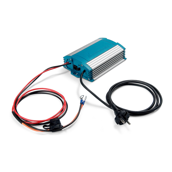
IVO SMART BATTERY CHARGER
Settings & Connections
1 RJ12 Jack, connection low battery, CSI alarm and PC
2 LED indicator, flashing = BULK/ABSORPTION, continuous = FLOAT
3 Remove jumper for diode compensation
4 Remove jumper for gel setting
5 Remove jumper for force float
6 In-line DC fuse
Tel.:
The Netherlands.
+31-20-3422100
ENGLISH
www.mastervolt.com
for applications. Please mind that this plug is not
Email: info@mastervolt.com
Web: www.mastervolt.com
October 2002

Verwandte Anleitungen für Mastervolt IVO SMART 12/10


Inhaltszusammenfassung für Mastervolt IVO SMART 12/10
- Seite 1 Productbeschrijving en toepassing Product description and application De IVO Smart 12/10 en de IVO Smart 24/06 zijn acculaders voor het laden en op spanning houden van The IVO SMART 12/10 and IVO SMART 24/06 are battery chargers for charging and maintaining the loodaccu’s en het voeden van de op de accu aangesloten gebruikers, in vast opgestelde installaties.
- Seite 2 I modelli IVO SMART 12/10 e IVO SMART 24/06 sono protetti contro gli spruzzi e la en instalaciones fijas. Los modelos IVO SMART 12/10 e IVO SMART 24/06 están protegidos contra polvere.