Herunterladen Inhalt Inhalt Diese Seite drucken

Werbung

Verfügbare Sprachen

Verfügbare Sprachen

SDTI-CP
Output Board
設置説明書 
Installation Instructions
Manuel d'installation
Installationsanleitung
Istruzioni per l'installazione
お買い上げいただきありがとうございます。
ご使用にあたっては、デジタルビデオカセットレコーダー本体
に付属の取扱説明書の「安全のために」 と「
をよくお読みください。お読みになったあとは、いつでも見ら
れるところに必ず保管してください。
本基板の取り付けは、必ずお買い上げ店またはソニーのサービ
ス窓口にご依頼ください。
DSBK-210
© 2000 Sony Corporation
2
3
ページ
Page 27
Seite 39
電気製品は、安全のための注意事項を守らないと、
火災や人身事故になることがあります。
3-205-213-01(1)
Page 15
Pagina 51
」 、 「
JP
GB
FR
DE
IT

Werbung

Inhaltsverzeichnis
loading

Inhaltszusammenfassung für Sony DSBK-210

  • Seite 1 Output Board 設置説明書  ページ Installation Instructions Page 15 Manuel d’installation Page 27 Installationsanleitung Seite 39 Istruzioni per l’installazione Pagina 51 お買い上げいただきありがとうございます。 電気製品は、安全のための注意事項を守らないと、 火災や人身事故になることがあります。 • ご使用にあたっては、デジタルビデオカセットレコーダー本体 に付属の取扱説明書の「安全のために」 と「 」 、 「 」 をよくお読みください。お読みになったあとは、いつでも見ら れるところに必ず保管してください。 • 本基板の取り付けは、必ずお買い上げ店またはソニーのサービ ス窓口にご依頼ください。 DSBK-210 © 2000 Sony Corporation...
  • Seite 3 日本語 目次 お客様へ ................. 概要 ..................追加されるメニュー項目 ..............5 フ ィ ー ド再生操作 ................6 DSBK-210 の構成品 ..............8 取り付け ................. お客様へ 9 ページ以降の設置説明 ( 「取り付け」の項)は、特約店およびソニーの サービス窓口用の設置説明書です。 日 本 お客様がこの設置説明書に記載された作業を行う と、 火災や、 感電やけ 語 がなどの人身事故につながる こ とがあ り ます。 お客様自身では絶対に取り付け作業をしないでく ださい。...
  • Seite 4 概要 SDTI-CPアウ ト プッ ト ボー ドDSBK-210は、 ソニーデジタルビデオカセッ ト レ コーダーDSR-2000のオプシ ョ ン基板です。 DSR-2000に本基板を取り付け ると、 SDTI-CP イ ンターフェースを装備した MPEG 対応のレコーダー (MSW-2000、 MAV-555/2000など)との接続が可能になり ます。 本基板の出力映像信号は、 MPEG2 4:2:2 Profile @ Main LevelによるI フレームオン リ ー方式のエンコー ド出力となっています。メニュー操作で 50/40/30Mbps のビッ ト レー ト が選択できます。...
  • Seite 5 追加されるメニュー項目 本基板をDSR-2000に取り付ける と、 セッ ト アップメニューに以下の項目が 追加されます。 ◆ メニューの操作方法については、 DSR-2000の取扱説明書をご覧く ださい。 表の設定の欄で□で囲んである値が、工場出荷時の設定です。 項目番号 項目名 設定 SUB STATUS モニター画面に文字情報と してスーパーイ ンポーズ するサブ情報を選択する。 :サブ情報は出力しない。 TC MODE :内蔵タイ ムコー ドジェネレーターの動 作状態 AUDIO MIX MODE :オーディ オ入力信号の ミ キ シング状態 TAPE REMAIN :テープ残量 CP OUT BIT RATE :メニュー項目...
  • Seite 6 概要 フィード再生操作 メニュー項目 111をFEEDに設定すると、 SDTI-CPイ ンターフェース対応 のノ ン リ ニア編集システムやディ スク レコーダーを接続して、 フ ィ ー ド再生を 行う こ とができます。 ご注意 • DSR-2000 では、 1 倍速のみのフ ィ ー ド再生に対応しています。 • DSR-2000のSDTI-CP出力は、 他の出力に対して3フレーム分遅れた位 相で出力されます。 フィード再生 DSR-2000に待ち受け記録が可能なレコーダー (RECEIVE STANDBY機 能を持つMAV-555/2000など)を接続して、 本機でフ ィ ー ド再生を行う こ と によ...
  • Seite 7 オートフィード再生 DSR-2000で記録開始点(IN点)と記録終了点(OUT点)を設定してオー ト フ ィ ー ド再生を行う と、待ち受け記録が可能なレコーダー側で、 IN 点から OUT 点までの区間をそのまま記録する こ とができます。 DSR-2000 で IN 点とOUT 点を設定する。 DMC EDITボタ ンを押したままPREVIEWボタ ンを押す。 DSR-2000は、 IN点の5秒前(メニュー項目001で変更可能)の位置ま でプリ ロールし再生を開始します。 OUT点を通過後2秒間ポス ト ロー ル走行してから、再生を停止します。 レコーダー側では、 IN 点からOUT 点までの区間が記録されます。...
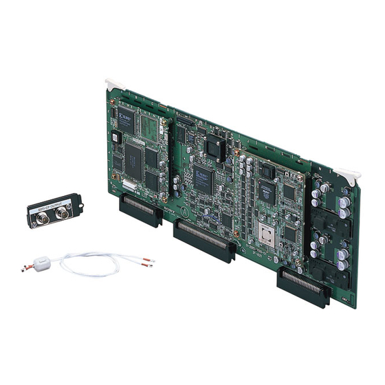
  • Seite 8 概要 DSBK-210 の構成品 DSBK-210は、下図の品目で構成されています。 IF-821 基板 ハ ー ネ ス( 連 同 軸 ケーブル) 外菊ワッシャー × コネクターパネル ネジ 、銀色...
  • Seite 9 取り付け DSBK-210をDSR-2000に取り付ける手順は、以下の通りです。 DSR-2000 の天板を外す。 ネジ3本をゆるめて、 天板ス ト ッパーおよびブラ ンクパネルから引き出 すよ う にして外す。 ネジ ブランクパネル ネジ ネジ 天板ストッパー 基板押さ えを外す。 ネジ1本をゆるめて、 基板押さ えを持ち上げ、 基板押さ えガイ ドがら引 き出すよ う にして外す。 基板押さえ 基板押さえガイド ネジ (続く )
  • Seite 10 取り付け ブラ ンクパネルを外す。 ご注意 ブラ ンクパネルとネジをなく さないよ う に保管してく ださい。 ネジ ブランクパネル ハーネス を、 コネク ターパネル取り付け用開口部を通してコネク ターパ ネルの2つのコネクターに接続した後、 コネクターパネルをDSR-2000 にネジ止めする。 ハーネス コネクターパネル 付属のネジ 銀色 とワッシャー...
  • Seite 11 ハーネスをIF-821基板上のDIF-109基板にあるCN200およびCN201 コネク ターに接続する。 (どち らのコネク ターにも同じ信号が出力されま す。 ) DIF-109 基板 CN200 CN201 、 コネクター IF-821 基板を基板スロ ッ ト (外側から4 番目) に差し込む。 差し込んだ基板下部の3個のコネクターとDSR-2000本体底部の3個 のコネク ターを合わせて、 コネク ターが接続されるまで基板をしっかり 押し下げる。 IF-821 基板 (続く )
  • Seite 12 取り付け ハーネス を、 基板スロ ッ ト脇の突起に沿わせて導き、 2つのケーブルホ ルダーと基板スロッ ト横の切込みにはめ込んだ後、 フェライ ト コアを ケーブルホルダー先の窪みに収める。 フェライトコア...
  • Seite 13 手順 2 で外した基板押さ えを元どおりに取りつける。 基板押さ えを基板押さ えガイ ドに合わせて押しこんでから、 ネジ穴を 合わせてネジを締める。 このとき、 基板押さ え下面の6対のツメが、 6個の基板スロ ッ ト に装着 されている基板をそれぞれはさむ位置になっている こ とを確認する。 基板押さえガイド ネジ 基板押さえのツメ DSR-2000 の天板を取り付ける。...
  • Seite 15: For The Customers In The Usa

    English For the customers in the USA This equipment has been tested and found to comply with the limits for a Class A digital device, pursuant to Part 15 of the FCC Rules. These limits are designed to provide reasonable protection against harmful interference when the equipment is operated in a commercial environment.
  • Seite 16: Inhaltsverzeichnis

    Components of the DSBK-210 ........20 Installation ..............21 Overview The DSBK-210 SDTI-CP Output Board is an optional board for the Sony DSR-2000/2000P Digital Videocassette Recorder. Installing this board in the DSR-2000/2000P allows connection to an MPEG-supporting recorder (such as the MSW-2000/ 2000P or MAV-555/2000), equipped with an SDTI-CP interface.
  • Seite 17: Additional Menu Items

    Additional Menu Items When this board is installed in the DSR-2000/2000P, the following additional items appear in the setup menus. For details of how to use the menus, refer to the Operating Instructions for the DSR-2000/2000P. In the table, the settings enclosed in a box are the factory default values.
  • Seite 18: Feed Playback Operations

    Overview Feed Playback Operations When menu item 111 is set to FEED, then by connecting a nonlinear editing system or disk recorder which supports the SDTI-CP interface, feed playback is possible. Notes • The DSR-2000/2000P only supports feed playback at normal speed.
  • Seite 19 Auto feed playback By setting the recording IN point and recording OUT point on the DSR-2000/2000P and carrying out auto feed playback, on a recorder capable of on-demand recording the segment from the IN point to the OUT point is recorded automatically. On the DSR-2000/2000P, set the IN and OUT points.
  • Seite 20: Components Of The Dsbk-210

    Overview Components of the DSBK-210 The DSBK-210 consists of the following items. IF-821 board Harness (two coaxial cables) Screw (M3 × 6, silver-colored) Washer Connector panel...
  • Seite 21: Installation

    To avoid such risks, installation should be performed by qualified service personnel. To install the DSBK-210 in the DSR-2000/2000P, proceed as follows. Remove the top cover of the DSR-2000/2000P.
  • Seite 22 Installation Remove the blank panel. Note Keep the blank panel and screw in a safe place for future use. Screw Blank panel Pass the harness through the opening in which the connector panel fits and connect it to the two connectors of the connector panel;...
  • Seite 23 Connect the harness to connectors CN200 and CN201 on the DIF-109 board on the IF-821 board. (Both connectors output the same signals.) DIF-109 board CN200 and CN201 connectors Insert the IF-821 board in the board slot (fourth from the outside). Align the three connectors on the bottom of the board with the three connectors inside the unit, and push the board firmly into place.
  • Seite 24 Installation Lay the harness along the projection beside the board slot, and insert it into the two cable holders and the groove alongside the board slot, then pack the ferrite core into the cavity by the cable holders. Ferrite core...
  • Seite 25 Replace the board retainer which you removed in step 2, in its original position. Push the board retainer into the board retainer guide, and fasten the screw in the screw hole. Check that the six claws on the underside of the board retainer engage with the boards in the slots to hold them in position.
  • Seite 27 E1 (résidentiel), E2 (commercial et industrie légère), E3 (urbain extérieur) et E4 (environnement EMC contrôlé ex. studio de télévision). Sommaire Aperçu ................28 Postes de menu additionnels ......... 29 Opéations de lecture Feed ..........30 Composants de la DSBK-210 ........32 Installation ..............33...
  • Seite 28: Aperçu

    Aperçu La carte de sortie SDTI-CP DSBK-210 est une carte optionnelle prévue pour le magnétoscope enregistreur numérique DSR-2000/2000P Sony. Son installation dans cet appareil permet la connexion d’un enregistreur assistant MPEG (tel que MSW-2000/2000P ou MAV-555/2000) équipé d’une interface SDTI-CP Les signaux vidéo sortis par cette carte sont conformes au...
  • Seite 29: Postes De Menu Additionnels

    Postes de menu additionnels Quand cette carte est installée dans un DSR-2000/2000P, les postes additionnels suivants apparaissent dans les menus d’implantation. Voir le mode d’emploi du DSR-2000/2000P pour les détails sur l’utilisation des menus. Dans le tableau, les réglages encadrés sont les valeurs usine par défaut.
  • Seite 30: Opéations De Lecture Feed

    Aperçu Opérations de lecture Feed Quand le poste de menu 111 est réglé à FEED, la lecture Feed devient possible en connectant un système de montage non- linéaire ou un enregistreur sur disque assistant l’interface SDTI-CP. Remarques • Le DSR-2000/2000P assiste seulement la lecture Feed à vitesse normale.
  • Seite 31 Lecture Auto Feed En réglant les seuils d’enregistrement IN et OUT sur le DSR- 2000/2000P et en effectuant une lecture Auto Feed sur un enregistreur permettant l’enregistrement sur demande, le segment entre les seuils IN et OUT est automatiquement enregistré. Réglez les seuils IN et OUT sur le DSR-2000/2000P.
  • Seite 32: Composants De La Dsbk-210

    Aperçu Composants de la DSBK-210 La carte DSBK-210 comprend les éléments suivants. Carte IF-821 Faisceau (deux câbles coaxiaux) Rondelle Vis (M3 × 6, Plaque à connecteur couleur argent)
  • Seite 33: Installation

    éléments périphériques. Pour éviter de tels risques, faites faire l’installation par un personnel de service qualifié. Procédez comme suit pour installer la carte DSBK-210 dans le DSR-2000/2000P. Retirez le cache supérieur du DSR-2000/2000P. Desserrez les trois vis et faites glisser le cache supérieur pour le dégager de la retenue supérieure et de la plaque de...
  • Seite 34 Installation Retirez la retenue de la carte. Desserrez la vis, puis soulevez la retenue de la carte pour la retirer du guide de retenue de carte. Retenue de la carte Guide de retenue de carte Retirez la plaque de suppression. Remarque Rangez la plaque de suppression et la vis à...
  • Seite 35 Passez le faisceau dans l’ouverture dans laquelle s’ajuste la plaque à connecteur et raccordez-le aux deux connecteurs de la plaque; puis fixez la plaque au DSR-2000/2000P avec la vis. Faisceau Plaque à connecteur Vis (couleur argent) et rondelle fournies Raccordez le faisceau aux connecteurs CN200 et CN201 sur la carte DIF-109 sur la carte IF-821.
  • Seite 36 Installation Insérez la carte IF-821 dans le logement pour carte (le quatrième à partir de l’extérieur). Alignez les trois connecteurs à la base de la carte sur les trois connecteurs dans l’appareil, et poussez la carte fermement en place. Carte IF-821...
  • Seite 37 Passez le faisceau le long de la saisie à côté du logement de carte, et insérez-le dans les deux serre-câbles et la cannelure le long du logement de carte, puis escamotez le noyau de ferrite dans la cavité près des serre-câbles. Noyau de ferrite (à...
  • Seite 38 Installation Remettez en place la retenue de carte retirée à l’étape 2. Poussez la retenue de carte dans le guide de retenue de carte et serrer la vis dans le trou à vis. Vérifiez que les six ergots sur le dessous de la retenue de carte sont engagés dans les cartes dans les fentes pour les maintenir en place.
  • Seite 39: Für Kunden In Europa

    E1 (Wohnbereich), E2 (kommerzieller und in beschränktem Maße industrieller Bereich), E3 (Stadtbereich im Freien) und E4 (kontrollierter EMV-Bereich, z.B. Fernsehstudio). Inhaltsverzeichnis Kurzbeschreibung ............40 Weitere Menüpositionen ..........41 “Feed Playback”-Betrieb ..........42 Die Komponenten der DSBK-210 ........ 44 Installation ..............45...
  • Seite 40: Kurzbeschreibung

    Kurzbeschreibung Die SDTI-CP-Ausgabekarte DSBK-210 ist eine optionale Karte für den Digitalvideorecorder DSR-2000P von Sony. Bei Installation dieser Karte in den DSR-2000P läßt sich ein für MPEG geeigneter Recorder (z.B. MSW-2000P oder MAV- 555/2000) mit SDTI-CP-Schnittstelle anschließen. Die über diese Karte ausgegebenen Videosignale entsprechem dem MPEG2 4:2:2 Profile @ Main Level “intra-frame only...
  • Seite 41: Weitere Menüpositionen

    Weitere Menüpositionen Nach Installation der Karte in den DSR-2000P erscheinen die nachstehend aufgeführten Parameter zusätzlich in den Einstellmenüs. Näheres zur Nutzung der Menüs findet sich in der Bedienungsanleitung des DSR-2000P. In der folgenden Tabelle sind die werkseitigen Vorgabeeinstellungen in Kasten gesetzt. Parameter- Parameter- Einstellungen...
  • Seite 42: Feed Playback"-Betrieb

    Kurzbeschreibung “Feed Playback”-Betrieb Bei Einstellung von Menüparameter 111 auf FEED ist Feed Playback möglich, sofern ein nichtlineares und mit der SDTI- CP-Schnittstelle kompatibles Editiersystem oder Disk- Recorder angeschlossen ist. Hinweise • Der DSR-2000P ist nur für Feed Playback mit normaler Geschwindigkeit ausgelegt.
  • Seite 43 Automatisches Feed Playback Durch Setzen des IN- und OUT-Punkts für Aufnahme am DSR-2000P und Ausführung der automatischen Feed Playback erfolgt bei einem Recorder mit der Möglichkeit für Aufnahme bei Bedarf die automatische Aufzeichnung der Passage zwischen IN- und OUT-Punkt. Setzen Sie den IN- und OUT-Punkt beim DSR-2000P. Halten Sie die DMC EDIT-Taste gedrückt, und drücken Sie gleichzeitig die PREVIEW-Taste.
  • Seite 44: Die Komponenten Der Dsbk-210

    Kurzbeschreibung Die Komponenten der DSBK-210 Die DSBK-210 besteht aus den folgenden Komponenten. Leiterplatte IF-821 Kabelbaum (zwei Koaxialkabel) Unterlegscheibe Schraube (M3 × 6, Anschlußfeld silberfarben)
  • Seite 45: Installation

    Brand, elektrischem Schlag und sonstigen Problemen. Überlassen Sie Installationsarbeiten ausschließlich qualifiziertem Fachpersonal. Zum Einbau der DSBK-210 in den DSR-2000P verfahren Sie wie folgt. Entfernen Sie die Abdeckung des DSR-2000P. Lösen Sie die drei Schrauben und schieben Sie die Abdeckung von der oberen Halterung und der Blindplatte weg.
  • Seite 46 Installation Entfernen Sie die Leiterplattenhalterung. Lockern Sie die Schraube, heben Sie die Halterung und ziehen Sie sie aus der Führung heraus. Leiterplattenhalterung Führung Schraube Entfernen Sie die Blindplatte. Hinweis Bewahren Sie die Blindplatte und die Schraube für spätere Verwendung auf. Schraube Blindplatte...
  • Seite 47 Führen Sie den Kabelbaum, durch die Öffnung für das Anschlußfeld, und schließen Sie sie an die beiden Stecker des Anschlußfelds an. Sichern Sie dann das Anschlußfeld mit der Schraube am DSR-2000P. Kabelbaum Anschlußfeld Mitgelieferte Schraube (silberfarben) und Unterlegscheibe Verbinden Sie den Kabelbaum mit Steckverbinder CN200 und CN201 der Leiterplatte DIF-109 an Leiterplatte IF-821 (die Ausgangssignale an beiden Steckverbindern sind identisch).
  • Seite 48 Installation Schieben Sie die Leiterplatte IF-821 in den vierten Schlitz von außen ein. Richten Sie die drei Steckverbinder der Leiterplatte mit den drei Steckverbindern im Innern des Geräts aus, und drücken Sie die Leiterplatte fest ein. Leiterplatte IF-821...
  • Seite 49 Verlegen Sie den Kabelbaum entlang des Vorsprungs neben dem Leiterplattenschlitz und führen Sie ihn in die beiden Kabelhalter und die Nut entlang des Leiterplattenschlitzes ein. Verstauen Sie dann den Ferritkern mit Hilfe der Kabelhalter im Hohlraum. Ferritkern (bitte wenden)
  • Seite 50 Installation Bringen Sie die in Schritt 2 entfernte Leiterplattenhalterung wieder an. Drücken Sie die Leiterplattenhalterung in die Führung, und ziehen Sie die Schraube fest. Vergewissern Sie sich davon, daß die sechs Greiferpaare an der Unterseite der Leiterplattenhalterung korrekt in die Leiterplatten eingreifen, um diese in Stellung zu sichern.
  • Seite 51 E1 (residenziali), E2 (commerciali e industriali leggeri), E3 (esterni urbani) e E4 (ambienti EMC controllati, ad esempio studi televisivi). Indice Descrizione ..............52 Voci di menu supplementari ......... 53 Operazioni di riproduzione feed ........54 Componenti della DSBK-210 ........56 Installazione ..............57...
  • Seite 52: Descrizione

    Descrizione La scheda di uscita SDTI-CP DSBK-210 è una scheda opzionale per il videoregistratore digitale Sony DSR-2000P. L’installazione di questa scheda sul DSR-2000P permette di collegare un registratore che supporta MPEG (come lo MSW- 2000P o MAV-555/2000), dotato di interfaccia SDTI-CP...
  • Seite 53: Voci Di Menu Supplementari

    Voci di menu supplementari Quando questa scheda è installata sul DSR-2000P, le seguenti voci supplementari appaiono nei menu di impostazione. Per dettagli su come usare i menu, fare riferimento alle Istruzioni per l’uso del DSR-2000P. Nella tabella le impostazioni racchiuse in riquadro sono i valori iniziali di fabbrica.
  • Seite 54: Operazioni Di Riproduzione Feed

    Descrizione Operazioni di riproduzione feed Quando la voce di menu 111 è impostata su FEED, collegando un sistema di montaggio non lineare o un registratore dischi che supporta l’interfaccia SDTI-CP è possibile la riproduzione feed. Note • Il DSR-2000P supporta solo la riproduzione feed a velocità normale.
  • Seite 55 Riproduzione feed automatica Impostando il punto IN di registrazione e il punto OUT di registrazione sul DSR-2000P ed eseguendo la riproduzione feed automatica, il segemtno dal punto IN al punto OUT viene registrato automaticamente su un registratore in grado di eseguire la registrazione su domanda.
  • Seite 56: Componenti Della Dsbk-210

    Descrizione Componenti della DSBK-210 La DSBK-210 consiste dei seguenti elementi. Scheda IF-821 Cablaggio (due cavi coassiali) Rondella Vite (M3 × 6, Pannello connettori color argento)
  • Seite 57: Installazione

    Per evitare tali rischi, l’installazione dovrebbe essere eseguita da personale tecnico qualificato. Per installare la DSBK-210 nel DSR-2000P, procedere come segue. Rimuovere il coperchio superiore del DSR-2000P. Allentare le tre viti e far scorrere il coperchio superiore via dal fermo superiore e dal pannello cieco.
  • Seite 58 Installazione Rimuovere il fermaschede. Allentare la vite, sollevare il fermaschede e tirarlo fuori dalla guida. Fermaschede Guida del fermaschede Vite Rimuovere il pannello cieco. Nota Conservare il pannello cieco e le viti in un luogo sicuro per usi futuri. Vite Pannello cieco...
  • Seite 59 Far passare il cablaggio attraverso l’apertura in cui entra il pannello connettori e collegarlo ai due connettori del pannello connettori; quindi fissare il pannello connettori al DSR-2000P con la vite. Cablaggio Pannello connettori Vite (color argento) e rondella in dotazione Collegare il cablaggio ai connettori CN200 e CN201 sulla scheda DIF-109 della scheda IF-821.
  • Seite 60 Installazione Inserire la scheda IF-821 nel vano scheda (quarto dall’esterno). Allineare i tre connettori sul fondo della scheda con i tre connettori all’interno dell’apparecchio e spingere saldamente la scheda in posizione. Scheda IF-821...
  • Seite 61 Disporre il cablaggio lungo la sporgenza a fianco del vano scheda e inserirlo nei due fermacavo e nella scanalatura lungo il vano scheda, quindi inserire l’anello di ferrite nell’incavo presso i fermacavo. Anello di ferrite (continua)
  • Seite 62 Installazione Rimettere il fermaschede rimosso al punto 2 nella sua posizione originale. Premere il fermaschede nella guida del fermaschede e fissare la vite nel foro vite. Controllare che le sei linguette sul lato inferiore del fermaschede si aggancino alle schede nei vani per trattenerle in posizione.
  • Seite 64 Sony Corporation Printed in Japan...

Inhaltsverzeichnis