Werbung
Verfügbare Sprachen
Verfügbare Sprachen
Quicklinks
I N S T R U C T I O N S
Type OTN-1991-SH
67203 10/12 (KPA)
English
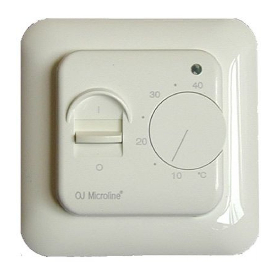
OTN-1991-SH, electronic thermostat for
mounting in standard wall box. The thermostat
is adjustable to required temperature from
+5/+40 ˚C. The LED shows that the heat is ON.
PRODUCTPROGRAM
OTN-1991-SH
with floor sensor
CE MARKING
OJ Electronics A/S declare under their own
responsibility that this product meets the
requirements of the European Council's direc-
tive 89/336 and successive modifications as to
electro-magnetic compatibility and the Council
directive 73/23 as to electrical equipment to be
applied within certain voltage ranges.
Standards applied
EN 61000-6-3, EN 61000-6-2, EN 60 730-1 and
EN 60730-2-9.
The product may only be energised when the
entire installation meets the current directive
requirements.
When the product is installed according to this
instructions guide and the current installation
guidelines, it is covered by factory guarantee.
If the product has been exposed to damage e.g.
in transport, it must be checked and overhauled
by qualified staff before the product is con-
nected to the power.
TECHNICAL DATA
Voltage ................230 VAC +10/-15%, 50/60 Hz
Current consumption .................................. 6 VA
Max. fuse .................................................... 16 A
Built-in switch .................................1-pole, 16 A
Output relay ............ Make contact - SPST - NO
Load .............................................14 A, 3200 W
Regulation principle ............................ ON / OFF
Temperature scale ..............................+5/-40 ºC
Difference/hysteresis ............................... 0.4 ºC
Setback temperature ..........................fixed 5 ºC
-control voltage signal ......................... 230 VAC
Scale limitation .................................. min./max.
Error circuit fuse at .................................. -20 ºC
Ambient temperature ........................... 0/+25 ºC
Dimensions ..................... H/80, W/80, D/50 mm
Protection ................................................... IP21
Because of tolerances the temperature range
may vary from +5/+45 °C.
The thermostat is free of maintenance.
CLASSIFICATION
The product is a class II device (reinforced
insulation) and the product must be connected
to the following conductors:
1)
Phase
(L)
2)
Neutral
(N)
WARNING – Important Safety Instructions
Isolate supply before carrying out any installa-
tion or maintenance work on this control unit
and associated components. This control unit
and associated components should only be
installed by a competent person (i, e qualified
electrician). Electrical installation to be in ac-
cordance with latest IEE Wiring Regulations and
appropriate Statutory Regulations.
Mounting of sensor
Floor sensor: Placed in an approved non
conductive installation pipe in accordance with
EN 61386-1, which is embedded in the floor.
(fig. 4) The pipe is closed in the end and placed
as high as possible in the concrete layer. The
installation pipe must be centered in between
the heating cable.
Sensor cable can be extended up to 100 m. by
means of a separate cable. If the extension ca-
ble is lighter than H05VV-F, it shall equally be in-
stalled in an unbroken installation pipe between
the sensor cable and the extension cable. Two
remaining cores of a multi-core cable which, for
example, supplies current to the floor heating
wires, must not be used. The switching peaks
of such current supply lines may create interfer-
ing signals that prevent optimum controller
function. If a shielded cable is used, the shield
must not be earthed but must be connected to
terminal 7. The two-core cable must be placed
in a separate pipe.
OTN-1991-SH units contain a fault interrupter
circuit which interrupts the heating in case of
disconnected or short-circuited sensors.
MOUNTING OF THERMOSTAT (fig. 1-3)
1. Remove the control knob (A).
2. Screw (B) should be unscrewed and the
cover lifted off.
3. Electrical connections can be made as
shown in the wiring diagram.
4. Mount the backing plate. Use only the round
holes.
5. The thermostat can now be filled into the wall
box.
- frame and cover is mounted
- thermostat knob is replaced
SETBACK TEMPERATURE
Setback of temperature setting is activated by a
230 V (L) signal from an external time switch to
terminal 5. Setback temperature is fixed 5 ˚C.
TEMPERATURE SETTING
OTN-1991-SH has a scale range of +5/+40
˚C. To assist the adjustment, the thermostat
has a LED (D) which will glow RED when the
heating is ON. The thermostat should be set to
maximum temperature setting until the desired
temperature of the room or floor is achieved.
The control knob should then be turned back
until the LED goes out. Fine adjustments can be
made over the next 1/2 days to suit individual
requirements.
THERMOSTAT ADJUSTMENT
When the room temperature has been sta-
bilized, the thermostat set position may be
adjusted to match actual room temperature.
Measure the temperature of the room with an
accurate thermometer. Remove control knob
and reposition it so that the indicated tem-
perature line shows the same as the measured
temperature. This adjustment can be done in
steps of 3 °C.
© 2012 OJ Electronics A/S
MAX./MIN. TEMPERATURE
A locking mechanism is positioned behind the
control knob to limit the amount of adjustment
possible. By loosening the little screw (C), the
scale range can be locked, e.g. between 20 ˚C
and 25 ˚C. The red ring indicates the maximum
temperature and the blue ring indicates the
minimum temperature.
FIGURES
Fig. 1
OTN-1991-SH cover with knob.
Fig. 2
Connection of OTN-1991-SH.
Fig. 3
Table with sensor values.
Fig. 4
Mounting of floor sensor.
Fig. 5
Mounting of thermostat.
Deutsch
OTN-1991-SH ist eine Thermostat-Serie
für den Einbau in standard Wanddosen. Die
gewünschte Temperatur kann zwischen +5°und
40 °C eingestellt werden. Die Leuchtdiode
leuchtet auf, wenn die Heizung eingeschaltet
is.
PRODUKTPROGRAMM
OTN-1991-SH
mit Bodenfühler
CE PRÜFZEICHEN
OJ Electronics A/S erklärt in eigener Verant-
wortung, dass dieses Produkt der Direktive
des Europäischen Rats 89/336 und den
nach folgenden Änderungen betreffs elektro-
magnetischer Kompatibilität sowie auch der
Direktive des Rats 73/23 betreffs Elektro-
ausrüstung zur Anwendung innerhalb gewissen
Spannungsgrenzen entspricht.
Berücksichtigte Standarde
EN 61000-6-3, EN 61000-6-2, EN 60 730-1
und EN 60730-2-9.
Das Produkt darf erst in Betrieb genommen
werden, nachdem sichergestellt ist, dass die
Gesamtinstallation die geltenden Forderungen
der Direktive erfüllt.
Nachdem das Produkt nach den Anweisungen
dieser Bedienungsanleitung und den Instal-
lationsvorschriften montiert ist, ist es von der
Werkgarantie umfasst.
Ist das Produkt z.B. im Transport beschädigt
worden, ist es vom qualifizierten Personal zu
besichtigen und zu prüfen, bevor das Produkt
ans Netz angeschlossen wird.
TECHNISCHE DATEN
Betriebsspannung ............. 230 VAC +10/-15%,
Stromverbrauch .......................................... 6 VA
Absicherung ............................................... 16 A
Eingebauter Ein/Ausschalter .........1-polig, 16 A
Ausgangsrelais ....Schliesskontakt - SPST - NO
Ausgangsstrom ............................14 A, 3200 W
Regelverfahren ................................... ON / OFF
Regelbarer Temperaturbereich ...........+5/-40 ºC
Hysteresis ................................................ 0.4 ºC
Einstellbare Nachtabsenkung .............. fest 5 ºC
-Steurspannung ................................... 230 VAC
50/60 Hz
1
Werbung

Verwandte Anleitungen für OJ Electronics OTN-1991-SH Series


Inhaltszusammenfassung für OJ Electronics OTN-1991-SH Series
- Seite 1 CE MARKING the heating cable. Fig. 3 Table with sensor values. OJ Electronics A/S declare under their own Sensor cable can be extended up to 100 m. by Fig. 4 Mounting of floor sensor. responsibility that this product meets the means of a separate cable.
- Seite 2 CE MAKERING drähte mit Strom versorgt, dürfen nicht verwen- tussen de sensorkabel en de thermostaat. De OJ Electronics A/S verklaart, dat het product det werden. Die Schaltspitzen einer derartigen twee overgebleven aders in een meeraderige voldoet aan de eisen, zoals gesteld in de richt- Stromversorgung können das Signal beein-...
- Seite 3 FIGUREN Fig. 1 OTN-1991-SH deksel met knop. Fig. 2 Aansluiting van OTN-1991-SH. Fig. 5 BR929A04a Fig. 3 Overzicht van voeler waarden. Fig. 4 Monteren van vloersensor. Fig. 5 Montage van de thermostaat. © 2012 OJ Electronics A/S...
- Seite 4 Dr. Huizingastraat 28 · 4507 AB Schoondijke Postbus 144 · 4500 AC Oostburg Tel: +31 (0) 117 401500 · Fax: +31 (0) 117 455606 info@speedheat.nl · www.speedheat.com The trademark is registered and belongs to OJ Electronics A/S · © 2012 OJ Electronics A/S...