Thermalright AXP-200 Muscle Handbuch
Vorschau ausblenden
Andere Handbücher für AXP-200 Muscle:
- Bedienungsanleitung (64 Seiten) ,
- Bedienungsanleitung (36 Seiten) ,
- Installationsanleitung (18 Seiten)
Werbung
Quicklinks
Werbung

Verwandte Anleitungen für Thermalright AXP-200 Muscle


Inhaltszusammenfassung für Thermalright AXP-200 Muscle
- Seite 1 Thermalright AXP-200 Muscle...
- Seite 3 AXP-200 Muscle Assembly Package × 4 × 8 × 7 × 4 × 5 × 5 × 5 × 1 × 1 Chill Factor × 1...
-
Seite 4: Exploded View
AXP-200 Muscle Intel 775/1150/1155/1156/1366 Exploded View Important! Before proceeding with installation, please check for the most up-to-date instructions at www.thermalright.com M3 L17 Screw TY-14013BW Fan Heatsink Body Mounting Plate M3 L6 Screw Anchoring Mount Screw Nut Intel Washer (small) M3 L10 Screw... - Seite 5 Mounting Plate ×1 Screw Nut ×4 M3 L10 Screw ×5 M3 L6 Screw ×7 Intel Washer (small) ×8 AMD Washer (big) ×4 Thermal Paste ×1 TY-14013BW Fan×1 M3 L17 Screw ×5 M3 L28 Screw ×5 The Ultimate Cooling Solutions! www.thermalright.com...
-
Seite 6: Installation Instructions
Installation Instructions: Step 1: Step 1 : Install the four screw pillars. Take one M3L10 screw and put one washer for Intel around the screw pillar. Snap it through one of holes around CPU socket from bottom towards top. Cap the screw pillar with the screw nut included and then tighten up. - Seite 7 (for Intel boards) underneath the fan for additional mounting holes. height before securing the fan onto the heatsink body. Step 6: Step 6 : Installation Completed Plug in the fan connector to the CPU PWM Fan socket on the motherboard. Installation complete. The Ultimate Cooling Solutions! www.thermalright.com...
- Seite 8 AXP-200 Muscle AM2/AM2+/AM3/AM3+/FM1/FM2 Exploded View Important! Before proceeding with installation, please check for the most up-to-date instructions at www.thermalright.com M3 L17 Screw TY-14013BW Fan Heatsink Body M3 L6 Screw Anchoring Mount Mounting Plate Screw Nut AMD Washer (big) M3 L10 Screw...
- Seite 9 Mounting Plate ×1 Screw Nut ×4 M3 L10 Screw ×5 M3 L6 Screw ×7 Intel Washer (small) ×8 AMD Washer (big) ×4 Thermal Paste ×1 TY-14013BW Fan×1 M3 L17 Screw ×5 M3 L28 Screw ×5 The Ultimate Cooling Solutions! www.thermalright.com...
- Seite 10 Installation Instructions: Step 1: Step 1 : Install the four screw pillars. Take one M3L10 screw and put one washer for AMD around the screw pillar. Snap it through one of holes around CPU socket from bottom towards top. Cap the screw pillar with the screw nut included and then tighten up.
- Seite 11 (for Intel boards) underneath the fan for additional mounting holes. height before securing the fan onto the heatsink body. Step 6: Step 6 : Installation Completed Plug in the fan connector to the CPU PWM Fan socket on the motherboard. Installation complete. The Ultimate Cooling Solutions! www.thermalright.com...
-
Seite 12: Explosionszeichnung
AXP-200 Muscle Intel 775/1150/1155/1156/1366 Explosionszeichnung Wichtig! Bitte prüfen Sie vor der Montage ob für Ihren Kühler aktualisierte Montagehinweise auf der Webseite www.thermalright.com verfügbar sind. M3 L17 Schraube TY-14013BW Lüfter Kühlkörper Befestigungsplatte M3 L6 Schraube Montagerahmen Rändelschraube Intel Unterlegscheibe (klein) M3 L10 Schraube... - Seite 13 Chill Factor Kühlkörper ×1 Montagerahmen ×1 Befestigungsplatte ×1 Rändelschraube ×4 M3 L10 Schraube ×5 M3 L6 Schraube ×7 Intel Unterlegscheibe AMD Unterlegscheibe Wärmeleitpaste ×1 (klein)×8 (groß)×4 TY-14013BW Lüfter×1 M3 L17 Schraube ×5 M3 L28 Schraube ×5 The Ultimate Cooling Solutions! www.thermalright.com...
- Seite 14 Installation Instructions: Schritt 1: Legen Sie die vier Unterlegscheiben (für Intel) über jede einzelne der vier M3L10 Schrauben. Führen Sie diese anschließend von unten durch die Montagelöcher des Mainboards, die sich um den CPU Sockel ziehen diese in diagonaler Reihenfolge (siehe Abbildung) vorsichtig an. Schritt 2: Setzen Sie den Montagerahmen auf die Rändelschrauben.
- Seite 15 Lüfters und drehen diese dann vorsichtig fest. Unterlegscheiben für Intel Plattformen unter den Lüfter bevor Sie ihn auf dem Kühlkörper befestigen. Schritt 6: Verbinden Sie den Lüfterstecker mit dem CPU PWM Lüfteranschluss auf dem Mainboard. Die Installation ist nun abgeschlossen. The Ultimate Cooling Solutions! www.thermalright.com...
- Seite 16 AXP-200 Muscle AM2/AM2+/AM3/AM3+/FM1/FM2 Explosionszeichnung Wichtig! Bitte prüfen Sie vor der Montage ob für Ihren Kühler aktualisierte Montagehinweise auf der Webseite www.thermalright.com verfügbar sind. M3 L17 Schraube TY-14013BW Lüfter Kühlkörper M3 L6 Schraube Montagerahmen Befestigungsplatte Rändelschraube AMD Unterlegscheibe (groß) M3 L10 Schraube...
- Seite 17 Chill Factor Kühlkörper ×1 Montagerahmen ×1 Befestigungsplatte ×1 Rändelschraube ×4 M3 L10 Schraube ×5 M3 L6 Schraube ×7 Intel Unterlegscheibe AMD Unterlegscheibe Wärmeleitpaste ×1 (klein)×8 (groß)×4 TY-14013BW Lüfter×1 M3 L17 Schraube ×5 M3 L28 Schraube ×5 The Ultimate Cooling Solutions! www.thermalright.com...
- Seite 18 Installation Instructions: Schritt 1: Legen Sie die vier Unterlegscheiben (für AMD) über jede einzelne der vier M3L10 Schrauben. Führen Sie diese anschließend von unten durch die Montagelöcher des Mainboards, die sich um den CPU Schritt 2: Setzen Sie den Montagerahmen auf die Rändelschrauben. Verwenden Sie die vier M3L6 Schrauben, um den Montagerahmen auf den Rändelschrauben zu befestigen.
- Seite 19 Lüfter bevor Sie ihn auf dem Kühlkörper befestigen. Schritt 6: Schließen Sie den Lüfterstecker an den CPU PWM Lüfteranschluss auf dem Mainboard an. Bitte prüfen Sie die ordnungsgemäße Funktion vor der Inbetriebnahme Ihres PC. Die Installation ist abgeschlossen. The Ultimate Cooling Solutions! www.thermalright.com...
- Seite 20 AXP-200 Muscle Intel 775/1150/1155/1156/1366...
- Seite 21 Chill Factor The Ultimate Cooling Solutions! www.thermalright.com...
- Seite 22 Installation Instructions:...
- Seite 23 The Ultimate Cooling Solutions! www.thermalright.com...
- Seite 24 AXP-200 Muscle AM2/AM2+/AM3/AM3+/FM1/FM2...
- Seite 25 Chill Factor The Ultimate Cooling Solutions! www.thermalright.com...
- Seite 26 Installation Instructions:...
- Seite 27 比例 1.000 The Ultimate Cooling Solutions! www.thermalright.com...
- Seite 28 Upgrading to 25mm thick 120mm x 120mm fans (or Thermalright TY-140 series fans) Step 1: Step 1:Secure the fan by screwing on the four M3L28 Screws, though the fan’s mounting holes. Step 2: Step 2: Installation Completed. Plug in the fan connector to the CPU PWM Fan socket on the motherboard.
- Seite 29 Upgrade auf 120 x 120 x 25 mm Lüfter (oder Thermalright TY-140 Lüfter) Schritt 1: Positionieren Sie den 25 mm hohen Lüfter auf den Kühlkörper und drehen anschließend die vier mitgelieferten M3L28 Schrauben durch die Löcher im Lüfterrahmen in die dafür vorgesehenen Montagebohrungen.
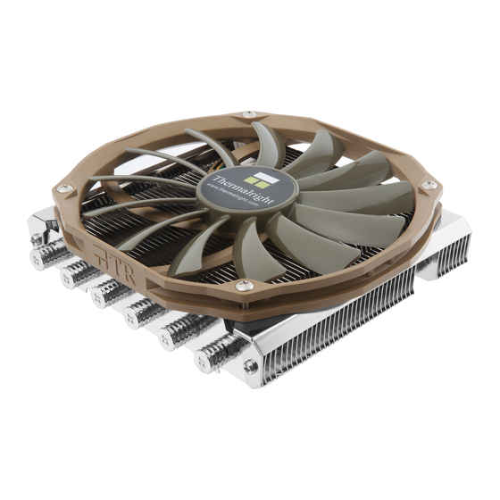
- Seite 31 AXP-200 Muscle Technical Spec Heatsink Specifications: Dimension: Length 149.99mm x Width 139.53mm x Height 59.65mm Weight: 430g (Heatsink only) Heatpipe: 6mm heatpipe*6 units Fan Specification: Dimension: L150mm x W140mm x H13mm Weight: 90g Fan speed: 700~1300RPM (PWM controlled) Fan noise: 21.7~30.6 dBA MAX (Test distance 1.0M) Airflow: 35.18~64.52CFM MAX...
- Seite 32 AXP-200 Muscle Kühlkörper Spezifikationen: Maße (in mm): Länge 149,99 x Breite 139,53 x Höhe 59,65 Heatpipe: 6 mm Heatpipe * 6 Stück Lüfter Spezifikationen: Maße (in mm): L150 x B140 x H13 Drehzahl: 700 ~ 1.300 U/min +/- 10% (PWM gesteuert) Lautstärke: 21,7 ~ 30,6 dBA max.
- Seite 33 AXP-200 Muscle The Ultimate Cooling Solutions! www.thermalright.com...
- Seite 34 AXP-200 Muscle...
- Seite 35 Thermalright -- Endorsed by Critics, Chosen by Experts...
- Seite 36 The Ultimate Cooling Solutions! www.thermalright.com TEL: +886-2-8663-6630 FAX: +886-2-8663-6645 EMAIL: sales@thermalright.com...