Herunterladen Inhalt Inhalt Diese Seite drucken
Panasonic AW-RP50E Bedienungsanleitung
Vorschau ausblenden Andere Handbücher für AW-RP50E:
Inhaltsverzeichnis

Werbung

Verfügbare Sprachen
  • DE

Verfügbare Sprachen

  • DEUTSCH, seite 40
Before operating this product, please read the instructions carefully and save this manual for
future use.
For instructions on how to operate this Remote Camera Controller and
how to establish its settings, refer to the "Operations and Settings" manual
(PDF file) which can be found on the CD-ROM supplied with the unit.
FJ0610TY5033 -FJ
Printed in Japan
Operating Instructions
Remote Camera Controller
AW-RP50E
Model No.
<Basics>
3TR006516FAA

Werbung

Inhaltsverzeichnis
loading

Inhaltszusammenfassung für Panasonic AW-RP50E

  • Seite 1 Operating Instructions <Basics> Remote Camera Controller AW-RP50E Model No. Before operating this product, please read the instructions carefully and save this manual for future use. For instructions on how to operate this Remote Camera Controller and how to establish its settings, refer to the “Operations and Settings” manual (PDF file) which can be found on the CD-ROM supplied with the unit.
  • Seite 2: Safety Precautions

    ENGLISH VERSION Safety precautions  DO NOT REMOVE PANEL COVERS BY CAUTION: UNSCREWING. TO REDUCE THE RISK OF FIRE OR SHOCK To reduce the risk of electric shock, do not HAZARD AND ANNOYING INTERFERENCE, remove the covers. No user serviceable parts USE THE RECOMMENDED ACCESSORIES inside.
  • Seite 3: Caution For Ac Mains Lead

    L or coloured RED. until a replacement cover is obtained. A replacement fuse cover can be purchased from your local Panasonic Dealer. How to replace the fuse 1. Open the fuse compartment with a screwdriver. IF THE FITTED MOULDED PLUG IS UNSUITABLE...
  • Seite 4 If you wish to discard this product, please contact your local authorities or dealer and ask for the correct method of disposal. Manufactured by: Panasonic Corporation, Osaka, Japan Importer’s name and address of pursuant to EU rules: Panasonic Testing Centre...
  • Seite 5: Inhaltsverzeichnis

    Contents Before use ..............5 Basic operations of the unit ........16 Overview ..............5 Basic operations for the menus ......17 Trademarks and registered trademarks ....5 Network settings ............18 About copyright and licence ........5 Setting the unit ............18 Concerning the ratings display ........5 Disclaimer of warranty..........5 Connections .............21 Network security .............5...
  • Seite 6: Before Use

     Overview   Disclaimer of warranty  IN NO EVENT SHALL Panasonic Corporation This unit is a controller which is designed to control BE LIABLE TO ANY PARTY OR ANY PERSON, remote cameras (cameras integrated with pan-tilt EXCEPT FOR REPLACEMENT OR REASONABLE...
  • Seite 7: Characteristics

    Characteristics Compact design Function for linkup with the switcher using IP   The unit features a compact design with its half-rack connection   By linking the unit with one AW-HS50 compact size width (210 mm) and its 4RU size (177 mm) depth.
  • Seite 8: Pan-Tilt Heads And Cameras Supported

    Pan-tilt heads and cameras supported  Remote cameras supported (cameras integrated with a pan-tilt head) AW-HE100, AW-HE50  Pan-tilt heads supported AW-PH360, AW-PH405, AW-PH650, AW-PH400 (AW-IF400 required)  Cameras supported (must be combined with the pan-tilt head supported) AW-HE870, AW-E860, AW-E750, AW-E650, AW-E350, AK-HC1500, AK-HC1800 Notes ...
  • Seite 9: Required Personal Computer Environment

    Required personal computer environment Run the software that is provided with the switcher on a host computer which satisfies the following specifications. ® Intel Core 2 DUO 2.4 GHz or faster recommended ® Memory Windows 512 MB or more ® ®...
  • Seite 10: Installation Precautions

    Installation precautions  In addition to heeding the points presented in the “Safety precautions”,  observe the following precautions as well. Be absolutely sure to ask your dealer to do the jobs of installing and connecting the unit. Connecting the power supply ...
  • Seite 11 Installation precautions Handle carefully!   Dropping the unit or subjecting it to strong impact or vibration may cause trouble and/or malfunctioning. Do not allow any foreign objects to enter inside the unit!   Allowing water, metal items, scraps of food or other foreign objects inside the unit may cause a fire and/or electric shocks.
  • Seite 12: Operating Precautions

    Operating precautions  In addition to heeding the points presented in the “Safety precautions”,  observe the following precautions as well. When the product is to be discarded Handle carefully. When the product is to be discarded at the end of its Do not drop the product, or subject it to strong shock service life, ask a specialized contractor to dispose of or vibration.
  • Seite 13: Parts And Their Functions

    Parts and their functions  Control panel  POWER ALARM CAMERA MENU PAGE GAIN/PED R/B GAIN R/B PED AWB/ABB SHUTTER EXIT STORE DELETE USER1 USER2 DETAIL SCENE/MODE CAMERA SETUP SYSTEM PRESET MEMORY / MENU IRIS AUTO PT ACTIVE CAMERA STATUS / SELECTION AUTO TELE ZOOM...
  • Seite 14 Parts and their functions  EXIT button [EXIT]  DELETE button [DELETE] Press this during menu operations to return to the Press this to delete the preset memory data for the previous hierarchical level. currently selected remote camera. When it is pressed again while its indicator is lit, the ...
  • Seite 15 Parts and their functions  Auto focus button [AUTO]  Auto iris button [AUTO] Press this to control the focus automatically. Press this to control the lens iris automatically. Button indicator ON: Button indicator ON: Auto focusing Auto iris Button indicator OFF: Button indicator OFF: Manual focusing Manual iris...
  • Seite 16: Rear Panel

    Parts and their functions   Rear panel SIGNAL GND POWER TO PAN/TILT HEAD 12V IN TALLY/GPI BOOT  DC IN socket [12V IN] (DC 12 V)  POWER switch [POWER] The AC adapter provided with the unit is connected When the POWER switch is set to the ON position, to this socket.
  • Seite 17: Basic Operations Of The Unit

    Basic operations of the unit Turn on the unit’s power. Adjust the lens iris. Set the POWER switch to the ON position. Use the IRIS dial to adjust the lens iris.   While the lens iris is being adjusted, a level Power is now supplied to the unit, and the POWER indicator lights.
  • Seite 18: Basic Operations For The Menus

    Basic operations for the menus Set the MENU button to ON.   Press the EXIT button to return the menu to its Press the MENU button and light its indicator. previous hierarchical level.   When the down arrow “” is displayed for a Select the target menu.
  • Seite 19: Network Settings

    Network settings This section describes how the unit’s network are set. Turn the F1 dial, and display the target setting item. Note 1. I P A D DR E S S ▼ Correct operation is not possible if the same IP 19 2 1 6 8 .0 0 0 .
  • Seite 20 Network settings Setting the IP address Setting the subnet mask On the [SYSTEM] menu, select the [NETWORK] On the [SYSTEM] menu, select the [NETWORK] menu, menu, and display [IP ADDRESS]. and display [SUBNETMASK]. Then operate the F2 dial to set the IP address. Then operate the F2 dial to set the subnet mask.
  • Seite 21 Network settings Setting the port number Set the port number for the remote camera. On the [SYSTEM] menu, select [CAM PORT] and display [PORT:CAM1] to [PORT:CAM100], and then operate the F2 dial to set the port number. 1. PO RT : C A M1 ▼...
  • Seite 22: Connections

    Connections  Example of IP connections   Connections with the AW-HE50 and AW-HS50  AW-HE50S AW-HE50S  SDI video LAN cable Monitor 2 signal Monitor 1 Switching hub  LAN cable Monitor Monitor AW-HS50 AW-RP50  Connecting a multiple number of the units with the AW-HE50 units ...
  • Seite 23: Example Of Serial Connections

    Connections  Example of serial connections   Connection with the AW-HE50  AW-HE50 Remote camera control signal  LAN cable AW-RP50 SIGNAL GND POWER RJ-45 relay TO PAN/TILT HEAD 12V IN TALLY/GPI BOOT adapter Monitor Multi-Interface Cable AW-CA20T6G 1: Use straight cables (category 5 or above) for these connections. 2: The multi-interface cable (AW-CA20T6G) is required for the serial connection with the AW-HE50.
  • Seite 24 Connections  Connections with the AW-PH400 and camera  Camera model: AW-HE870, AW-E860, AW-E750, AW-E650, AW-E350, AK-HC1500 or AK-HC1800 Zoom lens  LAN cable max. 1000 m max. 500 m AW-RP50 AW-PH400 SIGNAL GND POWER TO PAN/TILT HEAD 12V IN TALLY/GPI BOOT Protocol Converter...
  • Seite 25 Connections  Connection with the AW-PH650  MULTI POWER AW-PH650 RJ-45 relay adapter  LAN cable AW-RP50 SIGNAL GND POWER TO PAN/TILT HEAD 12V IN TALLY/GPI BOOT G/L input Monitor : Use straight cables (category 5 or above) for these connections. 24 (E)
  • Seite 26: Settings For Connection With The Remote Cameras

    Connections There are two procedures for the connection settings,  Settings for connection with  and these are described in “Settings for connection the remote cameras with the remote cameras” and “Settings for connection with the switcher”. Either serial connection “Serial” or IP connection There are two series of steps to be taken for “Settings “Network”...
  • Seite 27 Connections  Setting the IP addresses   If the IP address for a detected remote camera matches the IP address set for a camera number automatically (auto IP (a camera number with a connection setting setting) other than “Serial”), the IP address setting for the remote camera will be used as is.
  • Seite 28 Connections  When setting the IP addresses for  the first time  Memo  The IP addresses are set while the remote cameras,   If the number of new devices detected exceeds switcher and unit are at their factory settings. the number of devices that can be registered (100 remote cameras and 1 switcher), [C/S OVER!] Note...
  • Seite 29 Connections Turn the F2 dial, select “Yes”, and then press the F2 dial. This starts the “Auto IP setting” process. When “Auto IP setting” has been initiated, the progress is shown by the number of displayed dots which are reduced one by one. AU TO S E T U P When all the operations have been completed successfully, “COMPLETE!”...
  • Seite 30 Connections  When introducing additional remote  Setting the IP address from the unit cameras or a switcher into an environment where similar existing [Remote camera settings] devices are already in use The unit sets the IP addresses for the remote cameras that have been detected by associating Even when additional remote cameras or switcher are them with camera numbers whose connection...
  • Seite 31 Connections Connect the additional remote cameras Turn the F2 dial, select “Yes”, and then and the switcher to be introduced and press the F2 dial. the unit to the network within the same This starts the “Auto IP setting” process. subnet.
  • Seite 32 Connections Changing the IP address on the unit to match Connect the additional remote cameras the IP address of the remote camera or and the switcher to be introduced and switcher the unit to the network within the same subnet. [Remote camera settings] The unit sets the IP addresses for the remote On the [SYSTEM] menu, select [AUTO...
  • Seite 33 Connections Turn the F2 dial, select “Yes”, and then press the F2 dial. This starts the “Auto IP setting” process. When “Auto IP setting” has been initiated, the progress is shown by the number of displayed dots which are reduced one by one. AU TO S E T U P When all the operations have been completed successfully, “COMPLETE!”...
  • Seite 34: Controlled By The Unit

    Connections  Changing the IP addresses  When the IP addresses are changed, a check for IP address duplication is conducted. of the camera numbers A check is carried out to verify whether there is any duplication with the IP addresses of the camera controlled by the unit numbers which were set to “Network”...
  • Seite 35: Changing The Camera Numbers

    Connections  Changing the camera   Changing the IP address of  numbers the switcher The camera numbers which have been set by “Auto IP The IP address of the switcher which was set by “Auto setting” can be changed. IP setting”...
  • Seite 36: Selecting The Remote Cameras To Be Operated

    Selecting the remote cameras to be operated Up to five remote cameras to be operated can be selected using the CAMERA STATUS/SELECTION buttons. MENU PAGE GAIN/PED R/B GAIN R/B PED AWB/ABB SHUTTER EXIT When one of the CAMERA STATUS/SELECTION buttons 1 to 5 is pressed, the indicator of the STORE DELETE DETAIL...
  • Seite 37 Selecting the remote cameras to be operated Up to 100 cameras can be divided into 1 to 20 groups by menu operations, and controlled by the unit. The selection procedure is described below. Set the MENU button to ON. Press the MENU button and light its indicator. Set the PRESET MEMORY/MENU 8 button (CAMERA) to ON.
  • Seite 38: Appearance

    Appearance Unit: mm POWER ALARM CAMERA MENU PAGE GAIN/PED R/B GAIN R/B PED AWB/ABB SHUTTER EXIT STORE DELETE DETAIL SCENE/MODE CAMERA SETUP SYSTEM USER1 USER2 PRESET MEMORY / MENU IRIS AUTO PT ACTIVE CAMERA STATUS / SELECTION AUTO TELE ZOOM WIDE FOCUS/ OTAF...
  • Seite 39: Specifications

    Specifications DC 12 V 10 % Power requirements: (AC adapter provided) Current consumption: 0.5 A (DC 12 V) indicates safety information.  AC adapter   GENERAL  Input: Ambient operating temperature: AC 100 V to 240 V, 1.3 A, 47-63 Hz 0 °C to +40 °C Output: Allowable humidity ranges:...
  • Seite 40: Sicherheitshinweise

    DEUTSCHE AUSGABE (GERMAN VERSION) Sicherheitshinweise  Öffnen nicht Gerät durch VORSICHT: Abschrauben von Gehäuseteilen. EMPFOHLENE ZUBEHÖR Vermeidung elektrischem Schlag VERWENDEN, UM DIE GEFAHR VON FEUER darf das Gehäuse nicht geöffnet werden. Im ELEKTRISCHEM SCHLAG SOWIE Geräteinneren befinden sich keine Teile, die vom STÖRUNGEN AUSZUSCHALTEN.
  • Seite 41 Dieses Symbol ist nur in der Europäischen Union gültig. Bitte treten Sie mit Ihrer Gemeindeverwaltung oder Ihrem Händler in Kontakt, wenn Sie dieses Produkt entsorgen möchten, und fragen Sie nach einer Entsorgungsmöglichkeit. Hergestellt von: Panasonic Corporation, Osaka, Japan Name und Adresse des Importeurs gemäß EU-Bestimmungen: Panasonic Testing Centre...
  • Seite 42: Konfigurationsweise Der Bedienungsanleitungen Des Modells

    Inhalt Vor dem Gebrauch .............4 Grundlegende Bedienung des Gerätes ....15 Übersicht ..............4 Grundlegende Menüoperationen ......16 Warenzeichen und eingetragene Warenzeichen ..4 Netzwerkeinstellungen..........17 Copyright und Lizenz ..........4 Einstellen des Gerätes ..........17 Bezüglich des Typenschilds ........4 Verbindungen............20 Haftungsausschluss ..........4 Beispiel von IP-Verbindungen .......20 Netzwerksicherheit ..........4 Beispiel für serielle Verbindungen ......21 Eigenschaften ............5...
  • Seite 43: Vor Dem Gebrauch

    Vor dem Gebrauch  Übersicht   Haftungsausschluss  Panasonic Corporation IST UNTER ANDEREM IN KEINEM Bei diesem Gerät handelt es sich um ein Steuergerät, DER UNTEN AUFGEFÜHRTEN FÄLLE GEGENÜBER das für die Fernsteuerung von Kameras (mit Schwenk- JURISTISCHEN PERSONEN ODER PERSONEN Neigeköpfen integrierte Kameras) und Schwenk-...
  • Seite 44: Eigenschaften

    Eigenschaften Kompaktes Design Funktion für Kopplung mit dem Bildmischpult über   Mit seiner Halbrack-Breite (210 m) und seiner IP-Verbindung   Durch Kopplung des Gerätes mit einem 4RU-Tiefe (177 mm) weist das Gerät ein kompaktes Design auf. kompakten Live-Bildmischpult AW-HS50 über Das Gerät hat die gleiche Größe wie das kompakte eine IP-Verbindung kann eine hocheffiziente Live-Bildmischpult AW-HS50 (Option), und wenn...
  • Seite 45: Unterstützte Schwenk-Neigeköpfe Und Kameras

    Unterstützte Schwenk-Neigeköpfe und Kameras  Unterstützte Netzwerkkameras (mit einem Schwenk-Neigekopf integrierte Kameras) AW-HE100, AW-HE50  Unterstützte Schwenk-Neigeköpfe AW-PH360, AW-PH405, AW-PH650, AW-PH400 (AW-IF400 erforderlich)  Unterstützte Kameras (müssen mit dem unterstützten Schwenk-Neigekopf kombiniert sein) AW-HE870, AW-E860, AW-E750, AW-E650, AW-E350, AK-HC1500, AK-HC1800 Hinweise ...
  • Seite 46: Erforderliche Pc-Umgebung

    Erforderliche PC-Umgebung Führen Sie die mit dem Bildmischpult gelieferte Software auf einem Hostcomputer aus, der die folgenden Spezifikationen erfüllt. ® Intel Core 2 DUO 2,4 GHz oder schneller empfohlen ® Arbeitsspeicher Windows 512 MB oder mehr ® ® ® ® Microsoft Windows Vista , Microsoft...
  • Seite 47: Installationshinweise

    Installationshinweise  Beachten Sie neben den unter “Sicherheitshinweise” aufgeführten Punkten  auch die folgenden Vorsichtsmaßnahmen. Überlassen Sie Installation und Anschluss des Gerätes unbedingt Ihrem Händler. Anschließen der Stromversorgung   Verwenden Sie nur das mit dem Gerät gelieferte Netzkabel und Netzgerät. ...
  • Seite 48 Installationshinweise Sorgfältig behandeln!   Fallenlassen des Gerätes oder Einwirkung starker Erschütterungen oder Vibrationen können Schäden und/ oder Funktionsstörungen verursachen. Verhüten Sie das Eindringen von Fremdkörpern in das Gerät!   Das Eindringen von Wasser, Metallteilen, Essenresten oder anderen Fremdkörpern in das Gerät kann einen Brand und/oder elektrische Schläge verursachen.
  • Seite 49: Vorsichtsmaßnahmen Zum Betrieb

    Vorsichtsmaßnahmen zum Betrieb  Beachten Sie neben den unter “Sicherheitshinweise” aufgeführten Punkten  auch die folgenden Vorsichtsmaßnahmen. Wenn das Produkt ausrangiert werden soll Vorsichtig handhaben. Wenn das Produkt am Ende seiner Lebensdauer Das Produkt nicht fallen lassen oder starken Stößen ausrangiert werden soll, beauftragen Sie einen bzw.
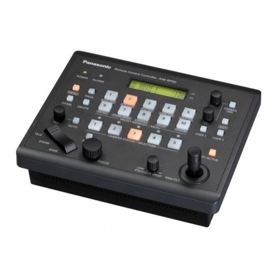
  • Seite 50: Teile Und Ihre Funktionen

    Teile und ihre Funktionen  Steuerpult  POWER ALARM CAMERA MENU PAGE GAIN/PED R/B GAIN R/B PED AWB/ABB SHUTTER EXIT STORE DELETE DETAIL SCENE/MODE CAMERA SETUP SYSTEM USER1 USER2 PRESET MEMORY / MENU IRIS AUTO PT ACTIVE CAMERA STATUS / SELECTION AUTO TELE ZOOM...
  • Seite 51: Benutzertasten [User1, User2]

    Teile und ihre Funktionen  Taste EXIT [EXIT]  Taste DELETE [DELETE] Drücken Sie diese Taste während der Drücken Sie diese Taste, um die Menüoperationen, um auf die vorherige Vorwahlspeicherdaten der gegenwärtig gewählten hierarchische Ebene zurückzukehren. Netzwerkkamera zu löschen. Wird die Taste bei leuchtender Lampe erneut ...
  • Seite 52 Teile und ihre Funktionen  Autofokustaste [AUTO]  Blendenautomatiktaste [AUTO] Drücken Sie diese Taste, um den Fokus Drücken Sie diese Taste, um die Objektivblende automatisch zu steuern. automatisch zu steuern. Tastenlampe EIN: Tastenlampe EIN: Automatische Fokussierung Automatische Blendeneinstellung Tastenlampe AUS: Tastenlampe AUS: Manuelle Fokussierung Manuelle Blendeneinstellung...
  • Seite 53: Rückwand

    Teile und ihre Funktionen   Rückwand SIGNAL GND POWER TO PAN/TILT HEAD 12V IN TALLY/GPI BOOT  Gleichstrom-Eingang [12V  Hauptschalter POWER [POWER] (12 V Gleichspannung) Wird der Hauptschalter auf die Position ON gestellt, leuchtet die Betriebslampe () auf, um anzuzeigen, Das mit dem Gerät gelieferte Netzgerät wird an dass das Gerät betriebsbereit ist.
  • Seite 54: Grundlegende Bedienung Des Gerätes

    Grundlegende Bedienung des Gerätes Schalten Sie das Gerät ein. Stellen Sie die Objektivblende ein. Drehen Sie den Knopf IRIS, um die Stellen Sie den Hauptschalter POWER auf ON. Objektivblende einzustellen. Das Gerät wird nun mit Strom versorgt, und die   Während die Objektivblende eingestellt wird, wird Lampe POWER leuchtet.
  • Seite 55: Grundlegende Menüoperationen

    Grundlegende Menüoperationen Stellen Sie die Taste MENU auf ON.   Drücken Sie die Taste EXIT, um auf die Drücken Sie die Taste MENU, so dass ihre Lampe vorhergehende hierarchische Ebene des Menüs aufleuchtet. zurückzukehren.   Erscheint der Abwärtspfeil “” für einen Wählen Sie das Zielmenü...
  • Seite 56: Netzwerkeinstellungen

    Netzwerkeinstellungen Dieser Abschnitt beschreibt die Netzwerkeinstellungen Drehen Sie den Knopf F1, um den des Gerätes. gewünschten Einstellungsposten anzuzeigen. Hinweis 1. I P AD D R ES S ▼ Korrekter Betrieb ist nicht möglich, wenn dieselbe 19 2 1 68 . 0 00 . 0 09 IP-Adresse bereits im selben Netzwerk existiert.
  • Seite 57 Netzwerkeinstellungen Einstellen der IP-Adresse Einstellen der Subnetzmaske Wählen Sie das Menü [NETWORK] im Menü Wählen Sie das Menü [NETWORK] im Menü [SYSTEM], und zeigen Sie [IP ADDRESS] an. [SYSTEM], und zeigen Sie [SUBNETMASK] an. Drehen Sie dann den Knopf F2, um die IP-Adresse Drehen Sie dann den Knopf F2, um die Subnetzmaske einzustellen.
  • Seite 58 Netzwerkeinstellungen Einstellen der Portnummer Stellen Sie die Portnummer für die Netzwerkkamera ein. Wählen Sie [CAM PORT] im Menü [SYSTEM], zeigen Sie [PORT:CAM1] bis [PORT:CAM100] an, und drehen Sie dann den Knopf F2, um die Portnummer einzustellen. 1 . P O R T :C AM 1 ▼...
  • Seite 59: Verbindungen

    Verbindungen  Beispiel von IP-Verbindungen   Verbindungen mit AW-HE50 und AW-HS50  AW-HE50S AW-HE50S SDI- Monitor 2  LAN-Kabel Videosignal Monitor 1 Switching-Hub  LAN-Kabel Monitor Monitor AW-HS50 AW-RP50  Verbinden mehrerer Geräte mit den Kameras AW-HE50  AW-HE50S AW-HE50S ...
  • Seite 60: Beispiel Für Serielle Verbindungen

    Verbindungen  Beispiel für serielle Verbindungen   Verbindung mit AW-HE50  AW-HE50 Netzwerkkamera-Steuersignal  LAN-Kabel AW-RP50 SIGNAL GND POWER RJ-45- TO PAN/TILT HEAD 12V IN TALLY/GPI BOOT Kupplung Monitor Multi-Verbindungskabel AW-CA20T6G 1: Verwenden Sie Straight-Kabel (Kategorie 5 oder höher) für diese Verbindungen. 2: Das Multi-Verbindungskabel (AW-CA20T6G) wird für die serielle Verbindung mit AW-HE50 benötigt.
  • Seite 61: Verbindungen Mit Aw-Ph400 Und Kamera

    Verbindungen  Verbindungen mit AW-PH400 und Kamera  Kameramodell: AW-HE870, AW-E860, AW-E750, AW-E650, AW-E350, AK-HC1500 oder AK-HC1800 Zoomobjektiv  LAN-Kabel max. 1000 m max. 500 m AW-RP50 AW-PH400 SIGNAL GND POWER TO PAN/TILT HEAD 12V IN TALLY/GPI BOOT Protokollkonverter AW-IF400 Kamera ...
  • Seite 62: Verbindung Mit Aw-Ph650

    Verbindungen  Verbindung mit AW-PH650  MULTI POWER AW-PH650 RJ-45-Kupplung  LAN-Kabel AW-RP50 SIGNAL GND POWER TO PAN/TILT HEAD 12V IN TALLY/GPI BOOT G/L-Eingang Monitor : Verwenden Sie Straight-Kabel (Kategorie 5 oder höher) für diese Verbindungen. 23 (G)
  • Seite 63: Ei Nstellungen Für Die Verbindung Mit Netzwerkkameras

    Verbindungen Zwei Verfahren sind für die Verbindungseinstellungen  Einstellungen für  verfügbar. Diese werden in “Einstellungen für die Verbindung mit Netzwerkkameras” und “Einstellungen die Verbindung mit für die Verbindung mit dem Bildmischpult” beschrieben. Netzwerkkameras Zwei Folgen von Schritten müssen für “Einstellungen für die Verbindung mit Netzwerkkameras”...
  • Seite 64 Verbindungen  Automatische Einstellung   Falls die IP-Adresse für eine erkannte Netzwerkkamera mit der für eine der IP-Adressen Kameranummer (eine Kameranummer mit (Automatische IP-Einstellung) einer anderen Verbindungseinstellung als “Serial”) eingestellten IP-Adresse übereinstimmt, Wenn “Automatische IP-Einstellung” ausgelöst wird, wird die IP-Adressen-Einstellung für die werden die IP-Adressen für die Netzwerkkameras und Netzwerkkamera unverändert verwendet.
  • Seite 65 Verbindungen  Bei erstmaliger Einstellung der   Notiz  IP-Adressen Die IP-Adressen werden eingestellt, während die   Falls die Zahl der erkannten neuen Vorrichtungen Netzwerkkameras, das Bildmischpult und das Gerät die Zahl der registrierbaren Vorrichtungen noch auf ihre Werksvorgaben eingestellt sind. (100 Netzwerkkameras und 1 Bildmischpult) überschreitet, wird [C/S OVER!] unten auf dem Hinweis...
  • Seite 66 Verbindungen Drehen Sie den Knopf F2, um “Yes” zu wählen, und drücken Sie dann den Knopf Dadurch wird der Vorgang “Automatische IP-Einstellung” gestartet. Wenn “Automatische IP-Einstellung” ausgelöst worden ist, wird der Fortschritt anhand der Zahl der Punkte angezeigt, die nacheinander verringert werden.
  • Seite 67 Verbindungen  Wenn zusätzliche Netzwerkkameras  Einstellen der IP-Adresse vom Gerät aus oder ein Bildmischpult in eine Umgebung eingeführt werden, in [Netzwerkkamera-Einstellungen] Das Gerät legt die IP-Adressen für die der ähnliche Vorrichtungen bereits erkannten Netzwerkkameras fest, indem es in Betrieb sind sie mit Kameranummern verbindet, deren Verbindungseinstellung auf “NoAsign”...
  • Seite 68 Verbindungen Schließen Sie die neu einzuführenden Drehen Sie den Knopf F2, um “Yes” zu zusätzlichen Netzwerkkameras, das wählen, und drücken Sie dann den Knopf Bildmischpult und das Gerät innerhalb desselben Subnetzes an das Netzwerk an. Dadurch wird der Vorgang “Automatische IP-Einstellung”...
  • Seite 69 Verbindungen Ändern der IP-Adresse am Gerät zur Schließen Sie die neu einzuführenden Anpassung an die IP-Adresse der zusätzlichen Netzwerkkameras, das Netzwerkkamera oder des Bildmischpults Bildmischpult und das Gerät innerhalb desselben Subnetzes an das Netzwerk an. [Netzwerkkamera-Einstellungen] Wählen Sie [AUTO SET IP] im Menü Das Gerät legt die IP-Adressen für die [SYSTEM], und zeigen Sie [AUTO SETUP] erkannten Netzwerkkameras fest, indem es...
  • Seite 70 Verbindungen Drehen Sie den Knopf F2, um “Yes” zu wählen, und drücken Sie dann den Knopf Dadurch wird der Vorgang “Automatische IP-Einstellung” gestartet. Wenn “Automatische IP-Einstellung” ausgelöst worden ist, wird der Fortschritt anhand der Zahl der Punkte angezeigt, die nacheinander verringert werden.
  • Seite 71: Ändern Der Ip-Adressen

    Verbindungen  Ändern der IP-Adressen  Wenn die IP-Adressen geändert werden, erfolgt eine Überprüfung auf IP-Adressen-Duplizierung. der vom Gerät gesteuerten Eine Überprüfung wird durchgeführt, um festzustellen, Kameranummern ob eine Duplizierung der IP-Adressen der Kameranummern vorliegt, die für den Posten [CAM1] Wenden Sie das folgende Verfahren an, um bis [CAM100] von [CAMERA CTL] im Menü...
  • Seite 72: Ändern Der Ip-Adresse Des Bildmischpults

    Verbindungen  Ändern der   Ändern der IP-Adresse des  Kameranummern Bildmischpults Die mit “Automatische IP-Einstellung” eingestellten Die mit “Automatische IP-Einstellung” eingestellte Kameranummern können geändert werden. IP-Adresse des Bildmischpults kann geändert werden. Die Änderung erfolgt, indem die IP-Adressen der aktuellen Kameranummern durch die IP-Adressen der Wählen Sie [SW IP ADR] im Menü...
  • Seite 73: Auswählen Der Zu Bedienenden Netzwerkkameras

    Auswählen der zu bedienenden Netzwerkkameras Bis zu fünf Netzwerkkameras können zum Zweck der Steuerung mithilfe der Tasten CAMERA STATUS/ SELECTION ausgewählt werden. MENU PAGE GAIN/PED R/B GAIN R/B PED AWB/ABB SHUTTER EXIT Wenn eine der Tasten CAMERA STATUS/ SELECTION 1 bis 5 gedrückt wird, leuchtet die Lampe STORE DELETE DETAIL...
  • Seite 74 Auswählen der zu bedienenden Netzwerkkameras Bis zu 100 Kameras können durch Menüoperationen in 1 bis 20 Gruppen eingeteilt und vom Gerät gesteuert werden. Das Auswahlverfahren wird im Folgenden beschrieben. Stellen Sie die Taste MENU auf ON. Drücken Sie die Taste MENU, so dass ihre Lampe aufleuchtet.
  • Seite 75: Aussehen

    Aussehen Einheit: mm POWER ALARM CAMERA MENU PAGE GAIN/PED R/B GAIN R/B PED AWB/ABB SHUTTER EXIT STORE DELETE DETAIL SCENE/MODE CAMERA SETUP SYSTEM USER1 USER2 PRESET MEMORY / MENU IRIS AUTO PT ACTIVE CAMERA STATUS / SELECTION AUTO TELE ZOOM WIDE FOCUS/ OTAF...
  • Seite 76: Technische Daten

    Technische daten Quellenspannung: 12 V Gleichspannung 10 % (mitgeliefertes Netzgerät) Stromverbrauch: 0,5 A (12 V Gleichspannung) ist die Sicherheitsinformation.  Netzgerät   ALLGEMEINES  Eingäng: Betriebstemperatur: 100 V bis 240 V Wechselstrom, 1,3 A, 47-63 Hz 0 °C bis +40 °C Ausgänge: Zulässige Luftfeuchtigkeitsbereiche: 12 V Gleichspannung, 3,5 A, 42 W...
  • Seite 77 Notizen...
  • Seite 78: Consignes De Sécurité

    VERSION FRANÇAISE (FRENCH VERSION) Consignes de sécurité  Ne pas dévisser le couvercle. ATTENTION: Pour réduire tout risque d’électrocution, ne pas POUR ÉVITER TOUT RISQUE D’INCENDIE, retirer le couvercle. Il ne se trouve à l’intérieur CHOCS ÉLECTRIQUES aucune pièce qui puisse être réparée par D’INTERFÉRENCES, N’UTILISER QUE LES l’utilisateur.
  • Seite 79 Pour supprimer ce produit, contactez les autorités locales ou votre revendeur afin de connaître la procédure d’élimination à suivre. Fabriqué par : Panasonic Corporation, Osaka, Japon Nom et adresse de l’importateur en accord avec les règlements de l’Union Européenne :...
  • Seite 80 Table des matières Avant utilisation ............4 Opérations de base de l’appareil ......15 Vue générale ............4 Opérations de base pour les menus ......16 Ma rques commerciales et marques commerciales Réglages de réseau ..........17 déposées ............4 Réglage de l’appareil ..........17 Au sujet du droit d’auteur et de la licence ....4 Connexions ..............20 Affichage des caractéristiques électriques ....4 Exemple de connexions IP ........20...
  • Seite 81: Avant Utilisation

     Déni de la garantie   Vue générale  EN AUCUN CAS Panasonic Corporation NE SERA TENU Cet appareil est une commande conçue pour POUR RESPONSABLE POUR TOUTE PARTIE OU TOUTE la caméras distantes (caméras avec tête de PERSONNE, À L’EXCEPTION DU REMPLACEMENT OU panoramique horizontal/vertical (ci-après abrégé...
  • Seite 82: Caractéristiques

    Caractéristiques Conception compacte Fonction de raccordement au commutateur par   L’appareil a une conception compacte avec sa connexion IP   Le raccordement de l’appareil à un commutateur largeur half-rack (210 mm) et sa profondeur 4RU (177 mm). live compact AW-HS50 par connexion IP permet L’appareil est de la même taille que le commutateur d’obtenir un environnement de fonctionnement très live compact AW-HS50 (option), et quand le...
  • Seite 83: Têtes Pan-Tilt Et Caméras Supportées

    Têtes pan-tilt et caméras supportées  Caméras distantes supportées (caméras à tête pan-tilt intégrée) AW-HE100, AW-HE50  Têtes pan-tilt supportées AW-PH360, AW-PH405, AW-PH650, AW-PH400 (AW-IF400 nécessaire)  Caméras supportées (doivent être combinées avec une tête pan-tilt supportée) AW-HE870, AW-E860, AW-E750, AW-E650, AW-E350, AK-HC1500, AK-HC1800 Remarques ...
  • Seite 84: Environnement Informatique Nécessaire

    Environnement informatique nécessaire Exécuter le logiciel fourni avec le mélangeur sur un ordinateur hôte qui présente les spécifications suivantes. ® Unité centrale Intel Core 2 DUO 2,4 GHz ou plus rapide recommandé ® Mémoire Windows 512 Mo ou plus ® ®...
  • Seite 85: Précautions D'installation

    Précautions d’installation  En plus des différents points présentés dans les “Consignes de sécurité”,  veuillez respecter également les précautions suivantes. Adressez-vous sans faute à votre revendeur pour effectuer les travaux d’installation et de raccordement de l’appareil. Raccordement de l’alimentation électrique ...
  • Seite 86 Précautions d’installation Manipuler avec précautions!   Une chute de l’appareil, un impact violent ou de fortes vibrations peuvent entraîner des défaillances et/ou une panne. Aucun corps étranger ne doit pénétrer à l’intérieur de l’appareil!   De l’eau, un objet métallique, des miettes ou tout autre corps étranger pénétrant à l’intérieur de l’appareil pourraient déclencher un incendie et/ou des décharges électriques.
  • Seite 87: Précautions D'utilisation

    Précautions d’utilisation  En plus des différents points présentés dans les “Consignes de sécurité”,  veuillez respecter également les précautions suivantes. Mise au rebut du produit Manipuler délicatement. Quand le produit atteint la fin de sa durée de vie, Ne jamais faire tomber l’appareil ni lui subir des chocs veuillez vous adresser à...
  • Seite 88: Nomenclature

    Nomenclature  Panneau de commande  POWER ALARM CAMERA MENU PAGE GAIN/PED R/B GAIN R/B PED AWB/ABB SHUTTER EXIT STORE DELETE DETAIL SCENE/MODE CAMERA SETUP SYSTEM USER1 USER2 PRESET MEMORY / MENU IRIS AUTO PT ACTIVE CAMERA STATUS / SELECTION AUTO TELE ZOOM...
  • Seite 89 Nomenclature  Bouton de sortie [EXIT]  Bouton d’effacement [DELETE] Appuyer dessus pendant les opérations de menu Appuyer dessus pour supprimer les données pour revenir au niveau hiérarchique précédent. de la mémoire préréglée de la caméra distante sélectionnée.  Boutons d’utilisateur [USER1, USER2] Si le bouton est pressé...
  • Seite 90 Nomenclature  Bouton de mise au point automatique  Bouton iris auto [AUTO] [AUTO] Le presser pour contrôler l’iris d’objectif Appuyer pour contrôler automatiquement la mise automatiquement. au point. Indicateur de bouton allumé: Indicateur de bouton allumé: Iris automatique Mise au point automatique Indicateur de bouton éteint: Indicateur de bouton éteint: Iris manuel...
  • Seite 91: Panneau Arrière

    Nomenclature   Panneau arrière SIGNAL GND POWER TO PAN/TILT HEAD 12V IN TALLY/GPI BOOT  Douille DC IN [12V IN] (12 V CC)  Interrupteur d’alimentation [POWER] L’adaptateur secteur fourni avec cet appareil se Quand l’interrupteur POWER est sur ON, le témoin connecte ici.
  • Seite 92: Opérations De Base De L'appareil

    Opérations de base de l’appareil Mettre sous tension. Ajuster l’iris d’objectif. Mettre l’interrupteur POWER sur ON. Ajuster à l’aide du cadran IRIS.   Pendant le réglage de l’iris d’objectif, L’appareil est maintenant alimenté, et le témoin POWER est allumé. l’indicateur de niveau s’affiche sur le panneau ...
  • Seite 93: Opérations De Base Pour Les Menus

    Opérations de base pour les menus Régler le bouton MENU à ON.   Appuyer sur le bouton EXIT pour remettre le Appuyer sur le bouton MENU, son indicateur menu à son niveau hiérarchique précédent. s’allumera.   Quand la flèche vers le bas “” est affichée pour un item de réglage, cela signifie que la valeur Sélectionner le menu cible.
  • Seite 94: Réglages De Réseau

    Réglages de réseau Cette section décrit comment le réseau de l’appareil Tourner le cadran F1 pour afficher l’item est réglé. de réglage cible. 1. I P AD D R ES S ▼ Remarque 19 2 1 68 . 0 00 . 0 09 Le fonctionnement correct est impossible si la même adresse IP existe déjà...
  • Seite 95 Réglages de réseau Réglage du masque de sous-réseau Réglage de l’adresse IP Au menu [SYSTEM], sélectionner le menu Au menu [SYSTEM], sélectionner le menu [NETWORK] et afficher [SUBNETMASK]. [NETWORK] et afficher [IP ADDRESS]. Puis opérer le cadran F2 pour régler le masque de Puis opérer le cadran F2 pour régler l’adresse IP.
  • Seite 96 Réglages de réseau Réglage du numéro de port Régler le numéro de port pour la caméra distante. Au menu [SYSTEM], sélectionner [CAM PORT] et afficher [PORT:CAM1] à [PORT:CAM100], puis opérer le cadran F2 pour régler le numéro de port. 1 . P O R T :C AM 1 ▼...
  • Seite 97: Connexions

    Connexions  Exemple de connexions IP   Connexions avec le AW-HE50 et le AW-HS50  AW-HE50S AW-HE50S Moniteur 2  Signal vidéo Câble LAN Concentrateur de Moniteur 1 commutation  Câble LAN Moniteur Moniteur AW-HS50 AW-RP50  Connexion de plusieurs appareils avec des unités AW-HE50 ...
  • Seite 98: Exemple De Connexions En Série

    Connexions  Exemple de connexions en série   Connexion avec le AW-HE50  AW-HE50 Signal de commande de caméra distante  Câble LAN AW-RP50 SIGNAL GND POWER Adaptateur de TO PAN/TILT HEAD 12V IN TALLY/GPI BOOT relais RJ-45 Moniteur Câble multi-interface AW-CA20T6G 1: Utiliser des câbles droits (catégorie 5 ou supérieure) pour ces connexions.
  • Seite 99 Connexions  Connexions avec le AW-PH400 et une caméra  Modèle de caméra: AW-HE870, AW-E860, AW-E750, AW-E650, AW-E350, AK-HC1500 ou AK-HC1800 Objectif zoom  Câble LAN 1000 mètres max. 500 mètres max. AW-RP50 AW-PH400 SIGNAL GND POWER TO PAN/TILT HEAD 12V IN TALLY/GPI BOOT...
  • Seite 100 Connexions  Connexion avec le AW-PH650  MULTI POWER AW-PH650 Adaptateur de relais RJ-45  Câble LAN AW-RP50 SIGNAL GND POWER TO PAN/TILT HEAD 12V IN TALLY/GPI BOOT Entrée G/L Moniteur : Utiliser des câbles droits (catégorie 5 ou supérieure) pour ces connexions. 23 (F)
  • Seite 101: Réglages Pour La Connexion Avec Les Caméras Distantes

    Connexions Il y a deux procédures pour les réglages de connexion,  Réglages pour la connexion  qui sont décrites dans “Réglages pour la connexion avec les caméras distantes” et “Réglages pour la avec les caméras distantes connexion avec le commutateur”. Une connexion en série “Serial”...
  • Seite 102 Connexions  Réglage automatique des   Si l’adresse IP pour une caméra distante détectée correspond à l’adresse IP pour un adresses IP (Réglage IP numéro de caméra (un numéro de caméra avec automatique) réglage de connexion autre que “Serial”), le réglage d’adresse IP pour la caméra distante Quand “Réglage IP automatique”...
  • Seite 103 Connexions  Au premier réglage des adresses IP   Notes  Les adresses IP sont réglées quand les caméras   Si le nombre de nouveaux dispositifs détectés distantes, le commutateur et l’appareil sont à leurs dépasse le nombre de dispositifs enregistrables réglages d’usine.
  • Seite 104 Connexions Tourner le cadran F2, sélectionner “Yes”, puis appuyer sur le cadran F2. Cela démarre le processus “Réglage IP automatique”. Quand “Réglage IP automatique” est initié, la progression est indiquée par le nombre de points affichés qui diminuent un à un. A U T O S ET U P Une fois toutes les opérations bien terminées, “COMPLETE!”...
  • Seite 105 Connexions  A l’introduction de caméras  Réglage de l’adresse IP à l’appareil distantes additionnelles ou d’un commutateur dans un [Réglages des caméras distantes] environnement où des dispositifs L’appareil règle les adresses IP pour les caméras similaires sont déjà utilisés distantes qui ont été...
  • Seite 106 Connexions Connecter les caméras distantes Tourner le cadran F2, sélectionner “Yes”, additionnelles et le commutateur à puis appuyer sur le cadran F2. introduire et l’appareil au réseau dans le Cela démarre le processus “Réglage IP même sous-réseau. automatique”. Quand “Réglage IP automatique” est initié, la progression est indiquée par le nombre de points Au menu [SYSTEM], sélectionner [AUTO affichés qui diminuent un à...
  • Seite 107 Connexions Changement de l’adresse IP à l’appareil pour Connecter les caméras distantes la correspondance à l’adresse IP de la caméra additionnelles et le commutateur à distante ou du commutateur introduire et l’appareil au réseau dans le même sous-réseau. [Réglages des caméras distantes] L’appareil règle les adresses IP pour les caméras Au menu [SYSTEM], sélectionner [AUTO distantes qui ont été...
  • Seite 108 Connexions Tourner le cadran F2, sélectionner “Yes”, puis appuyer sur le cadran F2. Cela démarre le processus “Réglage IP automatique”. Quand “Réglage IP automatique” est initié, la progression est indiquée par le nombre de points affichés qui diminuent un à un. A U T O S ET U P Une fois toutes les opérations bien terminées, “COMPLETE!”...
  • Seite 109 Connexions  Changement des adresses  Quand les adresses IP sont changées, un contrôle de duplication des adresses IP est exécuté. IP des numéros de caméra Un contrôle est exécuté pour vérifier s’il n’y a pas contrôlés par l’appareil. de duplication avec les adresses IP des numéros de caméra, qui ont été...
  • Seite 110: Changement Des Numéros De Caméra

    Connexions  Changement des numéros   Changement de l’adresse IP  de caméra du commutateur Les numéros de caméra qui ont été réglés par L’adresse IP du commutateur qui a été réglée à “Réglage IP automatique” peuvent être modifiés. “Réglage IP automatique”...
  • Seite 111: Sélection Des Caméras Distantes À Opérer

    Sélection des caméras distantes à opérer Jusqu’à cinq caméras distantes à opérer peuvent être sélectionnées à l’aide des boutons CAMERA STATUS/ SELECTION. MENU PAGE GAIN/PED R/B GAIN R/B PED AWB/ABB SHUTTER EXIT Quand un des boutons CAMERA STATUS/ SELECTION 1 à 5 est pressé, le témoin du bouton STORE DELETE DETAIL...
  • Seite 112 Sélection des caméras distantes à opérer Jusqu’à 100 caméras peuvent être divisées en 1 à 20 groupes par des opérations de menu, et contrôlées par l’appareil. La procédure de sélection est décrite ci-dessous. Régler le bouton MENU à ON. Appuyer sur le bouton MENU de sorte que son indicateur s’allume.
  • Seite 113: Aspect Extérieur

    Aspect extérieur Unité: mm POWER ALARM CAMERA MENU PAGE GAIN/PED R/B GAIN R/B PED AWB/ABB SHUTTER EXIT STORE DELETE DETAIL SCENE/MODE CAMERA SETUP SYSTEM USER1 USER2 PRESET MEMORY / MENU IRIS AUTO PT ACTIVE CAMERA STATUS / SELECTION AUTO TELE ZOOM WIDE FOCUS/...
  • Seite 114: Fiche Technique

    Fiche technique Source d’alimentation: 12 V CC 10 % (Adaptateur secteur fourni) Consommation de courant: 0,5 A (12 V CC) Informations concernant la sécurité.  Adaptateur secteur   Données générales  Entrée: Température de fonctionnement ambiante: 100 V à 240 V CA, 1,3 A, 47-63 Hz 0 °C à...
  • Seite 115 Notes...
  • Seite 116: Precauzioni Per La Sicurezza

    VERSIONE ITALIANA (ITALIAN VERSION) Precauzioni per la sicurezza  NON TOGLIERE COPERCHIO PRECAUZIONE: SVITANDOLO. PER RIDURRE I PERICOLI D’INCENDIO O Per ridurre i pericoli di scosse elettriche, non Dl SCOSSE ELETTRICHE E Dl FASTIDIOSE togliere il coperchio. All’interno non ci sono parti INTERFERENZE, USARE SOLTANTO...
  • Seite 117 Qualora si desideri smaltire questo prodotto, contattare le autorità locali o il rivenditore e chiedere informazioni sul metodo corretto di smaltimento. Fabbricato da: Panasonic Corporation, Osaka, Giappone Nome e indirizzo dell'importatore in conformità con le normative UE: Panasonic Testing Centre...
  • Seite 118 Sommario Prima dell’uso ............4 Operazioni basilari dell’unità ........15 Descrizione generale ..........4 Operazioni basilari dei menu ........16 Marchi di fabbrica e marchi di fabbrica registrati ..4 Impostazioni di rete ..........17 Riguardo a copyright e licenza ........4 Configurazione dell’unità ........17 Informazioni sull’indicazione delle specifiche ..4 Collegamenti ............20 Esonero dalla garanzia ...........4 Esempio di connessione IP ........20...
  • Seite 119: Prima Dell'uso

     Esonero dalla garanzia   Descrizione generale  IN NESSUN CASO Panasonic Corporation DOVRÀ La presente unità è un controller progettato per ESSERE RITENUTA RESPONSABILE NEI CONFRONTI DI controllare videocamere remote (videocamere ALCUNA PARTE O PERSONA, FATTA ECCEZIONE PER LA...
  • Seite 120: Caratteristiche

    Caratteristiche Design compatto Funzione di collegamento con lo switcher tramite   L’unità è caratterizzata da un design compatto, con connessione IP   Collegando l’unità al live switcher compatto larghezza a mezzo rack (210 mm) e profondità 4RU (177 mm). AW-HS50 mediante una connessione IP, è...
  • Seite 121: Te Ste Di Panoramica Orizzontale/Verticale E Videocamere Supportate

    Teste di panoramica orizzontale/verticale e videocamere supportate  Videocamere remote supportate (videocamere integrate con una testa di panoramica orizzontale/verticale) AW-HE100, AW-HE50  Teste di panoramica orizzontale/verticale supportate AW-PH360, AW-PH405, AW-PH650, AW-PH400 (necessario l’AW-IF400)  Videocamere supportate (da combinare con una testa di panoramica orizzontale/verticale supportata) AW-HE870, AW-E860, AW-E750, AW-E650, AW-E350, AK-HC1500, AK-HC1800 Note...
  • Seite 122: Ambiente Necessario Sul Personal Computer

    Ambiente necessario sul personal computer Avviare il software in dotazione con lo switcher su un computer host che soddisfi le seguenti specifiche. ® Consigliato Intel Core 2 DUO 2,4 GHz o superiore ® Memoria Windows Almeno 512 MB ® ® ®...
  • Seite 123: Precauzioni Per L'installazione

    Precauzioni per l’installazione  Oltre ai punti presentati alla sezione “Precauzioni per la sicurezza”, rispettare  anche le seguenti precauzioni. Consultare il rivenditore per informazioni sull’installazione e il collegamento dell’unità. Collegamento dell’alimentazione   Utilizzare esclusivamente il cavo di alimentazione e l’alimentatore c.a. in dotazione con l’unità. ...
  • Seite 124 Precauzioni per l’installazione Maneggiare con cura!   Se l’unità cade oppure subisce urti o vibrazioni di notevole entità, potrebbero verificarsi problemi e/o malfunzionamenti. Non consentire l’ingresso di corpi estranei all’interno dell’unità!   Se acqua, oggetti metallici, briciole o altri corpi estranei penetrano nell’unità, potrebbero verificarsi incendi o scosse elettriche.
  • Seite 125: Precauzioni Per L'uso

    Precauzioni per l’uso  Oltre ai punti presentati alla sezione “Precauzioni per la sicurezza”, rispettare  anche le seguenti precauzioni. Smaltimento del prodotto Maneggiare con cura. Per disfarsi del prodotto al termine della sua vita Non far cadere l’unità ed evitare che subisca forti urti utile, rivolgersi a un centro specializzato, in modo da o vibrazioni.
  • Seite 126: Parti E Funzioni

    Parti e funzioni  Pannello comandi  POWER ALARM CAMERA MENU PAGE GAIN/PED R/B GAIN R/B PED AWB/ABB SHUTTER EXIT STORE DELETE DETAIL SCENE/MODE CAMERA SETUP SYSTEM USER1 USER2 PRESET MEMORY / MENU IRIS AUTO PT ACTIVE CAMERA STATUS / SELECTION AUTO TELE ZOOM...
  • Seite 127 Parti e funzioni  Tasto EXIT [EXIT]  Tasto DELETE [DELETE] Premere il tasto durante le operazioni a menu per Premere il tasto per eliminare i dati delle memorie tornare al livello gerarchico precedente. personalizzate della videocamera remota correntemente selezionata. ...
  • Seite 128 Parti e funzioni  Tasto di regolazione automatica del  Tasto di messa a fuoco automatica [AUTO] diaframma [AUTO] Premere il tasto per regolare automaticamente la messa a fuoco. Premere il tasto per regolare automaticamente il diaframma obiettivo. Indicatore del tasto acceso: Messa a fuoco automatica Indicatore del tasto acceso: Diaframma automatico...
  • Seite 129: Pannello Posteriore

    Parti e funzioni   Pannello posteriore SIGNAL GND POWER TO PAN/TILT HEAD 12V IN TALLY/GPI BOOT  Attacco DC IN [12V IN] (C.c. 12 V)  Interruttore di accensione [POWER] L’alimentatore c.a. in dotazione con l’unità viene Impostando l’interruttore POWER su ON, collegato a questo attacco.
  • Seite 130: Operazioni Basilari Dell'unità

    Operazioni basilari dell’unità Accendere l’unità. Regolare il diaframma obiettivo. Utilizzare la ghiera IRIS per regolare il diaframma Spostare l’interruttore POWER in posizione ON. obiettivo. L’unità viene alimentata e l’indicatore POWER si   Durante la regolazione del diaframma obiettivo, accende. viene visualizzato un misuratore di livello sul ...
  • Seite 131: Operazioni Basilari Dei Menu

    Operazioni basilari dei menu Impostare il tasto MENU su ON.   Premere il tasto EXIT per tornare al livello Premere il tasto MENU per accenderne gerarchico precedente nel menu. l’indicatore.   Se per una voce di impostazione è visualizzata una freccia verso il basso “”, il valore indicato Selezionare il menu desiderato.
  • Seite 132: Impostazioni Di Rete

    Impostazioni di rete Questo capitolo descrive la configurazione delle Ruotare la ghiera F1 e visualizzare la voce impostazioni di rete dell’unità. di configurazione desiderata. 1. I P AD D R ES S ▼ Nota 19 2 1 68 . 0 00 . 0 09 Il funzionamento corretto non è...
  • Seite 133 Impostazioni di rete Impostazione dell’indirizzo IP Impostazione della subnet mask Nel menu [SYSTEM], selezionare il menu [NETWORK] Nel menu [SYSTEM], selezionare il menu [NETWORK] e visualizzare [IP ADDRESS]. e visualizzare [SUBNETMASK]. Quindi, utilizzare la ghiera F2 per impostare l’indirizzo Quindi, utilizzare la ghiera F2 per impostare la subnet mask.
  • Seite 134 Impostazioni di rete Impostazione del numero di porta Impostare il numero di porta della videocamera. Nel menu [SYSTEM], selezionare [CAM PORT] e visualizzare le voci da [PORT:CAM1] a [PORT:CAM100], quindi utilizzare la ghiera F2 per impostare il numero di porta. 1 .
  • Seite 135: Collegamenti

    Collegamenti  Esempio di connessione IP   Collegamenti con l’AW-HE50 e l’AW-HS50  AW-HE50S AW-HE50S Monitor 2  Segnale Cavo LAN video SDI Hub di Monitor 1 commutazione  Cavo LAN Monitor Monitor AW-HS50 AW-RP50  Collegamento di più unità con le unità AW-HE50 ...
  • Seite 136: Esempi Di Collegamenti Seriali

    Collegamenti  Esempi di collegamenti seriali   Collegamento con l’AW-HE50  AW-HE50 Segnale di controllo videocamera remota  Cavo LAN AW-RP50 SIGNAL GND POWER Scheda di TO PAN/TILT HEAD 12V IN TALLY/GPI BOOT rinvio RJ-45 Monitor Cavo multi-interfaccia AW-CA20T6G 1: Per questi collegamenti, utilizzare cavi dritti (categoria 5 o superiore).
  • Seite 137 Collegamenti  Collegamenti con l’AW-PH400 e la videocamera  Modello videocamera: AW-HE870, AW-E860, AW-E750, AW-E650, AW-E350, AK-HC1500 o AK-HC1800 Obiettivo zoom  Cavo LAN 1000 metri max. 500 metri max. AW-RP50 AW-PH400 SIGNAL GND POWER TO PAN/TILT HEAD 12V IN TALLY/GPI BOOT Convertitore...
  • Seite 138 Collegamenti  Collegamento con l’AW-PH650  MULTI POWER AW-PH650 Scheda di rinvio RJ-45  Cavo LAN AW-RP50 SIGNAL GND POWER TO PAN/TILT HEAD 12V IN TALLY/GPI BOOT Ingresso G/L Monitor : Per questi collegamenti, utilizzare cavi dritti (categoria 5 o superiore). 23 ( I )
  • Seite 139: Im Postazioni Per Il Collegamento Con Le Videocamere Remote

      Il collegamento seriale “Serial” non può essere tra un multiplo numero (fino a 5 unità) di controller di selezionato per i numeri di videocamera da CAM6 videocamere remote AW-RP50E collegati alla stessa a CAM100. rete, le operazioni vanno eseguite usando il “Setup Software”...
  • Seite 140 Collegamenti  Configurazione automatica   Se l’indirizzo IP di una videocamera remota rilevata è identico a quello impostato per un degli indirizzi IP numero di videocamera (con impostazione di (Configurazione IP collegamento diversa da “Serial”), l’indirizzo IP impostato per la videocamera remota verrà automatica) utilizzato senza variazioni.
  • Seite 141 Collegamenti  Prima configurazione degli indirizzi IP   Promemoria  Gli indirizzi IP vengono impostati mentre le videocamere remote, lo switcher e l’unità sono   Se il numero di nuovi dispositivi rilevati supera configurati con le impostazioni di fabbrica. il numero massimo di dispositivi registrabili (100 videocamere remote e 1 switcher), il Nota...
  • Seite 142 Collegamenti Ruotare la ghiera F2, selezionare “Yes” e premere la ghiera F2. La procedura “Configurazione IP automatica” viene avviata. Durante l’esecuzione di “Configurazione IP automatica”, lo stato di avanzamento dell’operazione viene indicato dai puntini visualizzati, che si riducono progressivamente. A U T O S ET U P Quando tutte le operazioni terminano con successo, viene visualizzato il messaggio “COMPLETE!”.
  • Seite 143 Collegamenti  Quando si introducono  Configurazione dell’indirizzo IP dall’unità videocamere remote o uno switcher in un ambiente dove sono già in uso [Impostazioni della videocamera remota] dispositivi simili L’unità imposta gli indirizzi IP delle videocamere remote collegate associandoli ai numeri di Anche se si introducono altre videocamere remote videocamera con impostazione di collegamento o uno switcher in un ambiente dove sono già...
  • Seite 144 Collegamenti Collegare le videocamere remote o lo Ruotare la ghiera F2, selezionare “Yes” e switcher supplementari e l’unità alla rete, premere la ghiera F2. all’interno della stessa subnet. La procedura “Configurazione IP automatica” viene avviata. Durante l’esecuzione di “Configurazione Nel menu [SYSTEM], selezionare il menu IP automatica”, lo stato di avanzamento [AUTO SET IP] e visualizzare [AUTO dell’operazione viene indicato dai puntini...
  • Seite 145 Collegamenti Modifica dell’indirizzo IP sull’unità, in modo Collegare le videocamere remote o lo da farlo corrispondere all’indirizzo IP della switcher supplementari e l’unità alla rete, videocamera remota o dello switcher all’interno della stessa subnet. [Impostazioni della videocamera remota] Nel menu [SYSTEM], selezionare il menu L’unità...
  • Seite 146 Collegamenti Ruotare la ghiera F2, selezionare “Yes” e premere la ghiera F2. La procedura “Configurazione IP automatica” viene avviata. Durante l’esecuzione di “Configurazione IP automatica”, lo stato di avanzamento dell’operazione viene indicato dai puntini visualizzati, che si riducono progressivamente. A U T O S ET U P Quando tutte le operazioni terminano con successo, viene visualizzato il messaggio “COMPLETE!”.
  • Seite 147 Collegamenti  Modifica degli indirizzi IP  Dopo aver modificato gli indirizzi IP, viene eseguito un controllo per rilevare eventuali duplicazioni degli dei numeri di videocamera indirizzi. controllati dall’unità Il controllo verifica la presenza di eventuali duplicazioni con gli indirizzi IP dei numeri di videocamera impostati Utilizzare la seguente procedura per collegare le su “Network”...
  • Seite 148: Modifica Dei Numeri Delle Videocamere

    Collegamenti  Modifica dei numeri delle   Modifica degli indirizzi IP  videocamere dello switcher È possibile modificare i numeri delle videocamere È possibile modificare l’indirizzo IP dello switcher configurati con “Configurazione IP automatica”. configurato con “Configurazione IP automatica”. I numeri vengono modificati sostituendo gli indirizzi IP dei numeri di videocamera correnti con gli indirizzi IP Nel menu [SYSTEM], selezionare il menu...
  • Seite 149: Selezione Delle Videocamere Remote Da Comandare

    Selezione delle videocamere remote da comandare È possibile selezionare fino a cinque videocamere remote da comandare con i tasti CAMERA STATUS/ SELECTION. MENU PAGE GAIN/PED R/B GAIN R/B PED AWB/ABB SHUTTER EXIT Premendo uno dei tasti CAMERA STATUS/ SELECTION da 1 a 5, l’indicatore del tasto STORE DELETE DETAIL...
  • Seite 150 Selezione delle videocamere remote da comandare Utilizzando il menu, è possibile dividere fino a 100 videocamere remote in 1 - 20 gruppi e controllarle dall’unità. La procedura di regolazione viene descritta di seguito. Impostare il tasto MENU su ON. Premere il tasto MENU per accenderne l’indicatore.
  • Seite 151: Aspetto

    Aspetto Unità: mm POWER ALARM CAMERA MENU PAGE GAIN/PED R/B GAIN R/B PED AWB/ABB SHUTTER EXIT STORE DELETE DETAIL SCENE/MODE CAMERA SETUP SYSTEM USER1 USER2 PRESET MEMORY / MENU IRIS AUTO PT ACTIVE CAMERA STATUS / SELECTION AUTO TELE ZOOM WIDE FOCUS/ OTAF...
  • Seite 152: Dati Tecnici

    Dati tecnici Tensione di alimentazione: C.c. 12 V 10 % (Alimentatore c.a. in dotazione) Consumo di corrente: 0,5 A (C.c. 12 V) sono le informazioni sulla sicurezza.  Alimentatore c.a.   Generali  Ingresso: Temperatura d’esercizio: C.a. 100 V - 240 V, 1,3 A, 47-63 Hz 0 °C - +40 °C Uscita: Gamme di umidità...
  • Seite 153 Appunti...
  • Seite 154: Precauciones De Seguridad

    VERSIÓN ESPAÑOLA (SPANISH VERSION) Precauciones de seguridad  NO QUITE CUBIERTA PRECAUCIÓN: DESATORNILLÁNDOLA. PARA REDUCIR RIESGO No quite la tapa para evitar el riesgo de INCENDIOS, SACUDIDAS ELÉCTRICAS sacudidas eléctricas. Las piezas del interior no INTERFERENCIAS MOLESTAS, requieren mantenimiento por parte del usuario. UTILICE SOLAMENTE LOS ACCESORIOS Solicite las reparaciones al personal de servicio RECOMENDADOS.
  • Seite 155 Si desea desechar este producto, póngase en contacto con las autoridades locales o con su distribuidor para que le informen sobre el método correcto de eliminación. Fabricado por: Panasonic Corporation, Osaka, Japón Nombre y dirección del importador conforme a las normas de la UE:...
  • Seite 156 Índice Operaciones básicas de la unidad ......15 Antes del uso .............4 Operaciones básicas para los menús ....16 Perspectiva general..........4 Ajustes de red ............17 Mar cas comerciales y marcas comerciales registradas ............4 Ajuste de la unidad ..........17 Acerca de los derechos de autor y de la licencia ..4 Conexiones ..............20 Ace rca de la visualización de las especificaciones Ejemplo de conexiones IP........20...
  • Seite 157: Antes Del Uso

     Perspectiva general   Renuncia de la garantía  Panasonic Corporation NO ACEPTA NINGÚN TIPO Esta unidad es un controlador que ha sido diseñado DE RESPONSABILIDAD CON PERSONAS LEGALES para controlar cámaras remotas (cámaras integradas O FÍSICAS, A EXCEPCIÓN DEL REEMPLAZO O con cabezales de panorámica-inclinación) y sistemas...
  • Seite 158: Características

    Características Diseño compacto Función de enlace con el conmutador utilizando la   Esta unidad es de diseño compacto con su anchura conexión IP   Enlazando la unidad con un conmutador en directo del tamaño de media estantería (210 mm) y su profundidad del tamaño 4RU (177 mm).
  • Seite 159: Cabezales De Panorámica-Inclinación Y Cámaras Compatibles

    Cabezales de panorámica-inclinación y cámaras compatibles  Cámaras remotas compatibles (cámaras integradas con un cabezal de panorámica- inclinación) AW-HE100, AW-HE50  Cabezales de panorámica-inclinación compatibles AW-PH360, AW-PH405, AW-PH650, AW-PH400 (AW-IF400 necesario)  Cámaras compatibles (deberán combinarse con el cabezal de panorámica-inclinación compatible) AW-HE870, AW-E860, AW-E750, AW-E650, AW-E350, AK-HC1500, AK-HC1800 Notas...
  • Seite 160: Ambiente De Ordenador Personal Requerido

    Ambiente de ordenador personal requerido Ejecute el software provisto con el conmutador en un ordenador anfitrión que satisfaga las especificaciones siguientes. ® Se recomienda Intel Core 2 DUO 2,4 GHz o más rápida ® Memoria Windows 512 MB o más ®...
  • Seite 161: Precauciones Para La Instalación

    Precauciones para la instalación  Además de seguir las indicaciones de las “Precauciones de seguridad”, tome  también las precauciones siguientes. Asegúrese absolutamente de solicitar a su concesionario que le haga los trabajos de instalación y conexión de la unidad. Conexión de la alimentación ...
  • Seite 162 Precauciones para la instalación ¡Maneje cuidadosamente la unidad!   La caída de la unidad o exponerla a impactos o vibraciones fuertes puede ser causa de problemas y/o fallos en el funcionamiento. ¡No permita que ningún objeto extraño entre en la unidad! ...
  • Seite 163: Precauciones De Manejo

    Precauciones de manejo  Además de seguir las indicaciones de las “Precauciones de seguridad”, tome  también las precauciones siguientes. Cuando tire el producto Maneje el producto cuidadosamente. Cuando tire el producto al final de su vida de servicio, No deje caer el producto ni lo someta a sacudidas o póngase en contacto con un contratista especializado vibraciones fuertes.
  • Seite 164: Partes Y Sus Funciones

    Partes y sus funciones  Panel de control  POWER ALARM CAMERA MENU PAGE GAIN/PED R/B GAIN R/B PED AWB/ABB SHUTTER EXIT STORE DELETE DETAIL SCENE/MODE CAMERA SETUP SYSTEM USER1 USER2 PRESET MEMORY / MENU IRIS AUTO PT ACTIVE CAMERA STATUS / SELECTION AUTO TELE ZOOM...
  • Seite 165 Partes y sus funciones  Botón EXIT [EXIT]  Botón DELETE [DELETE] Pulse este botón durante las operaciones con Pulse este botón para eliminar los datos de la menú para volver al nivel jerárquico anterior. memoria de preajustes de la cámara remota actualmente seleccionada.
  • Seite 166 Partes y sus funciones  Botón de enfoque automático [AUTO]  Botón de iris automático [AUTO] Pulse este botón para controlar automáticamente el Pulse este botón para controlar automáticamente el enfoque. iris del objetivo. Indicador del botón ON: Indicador del botón ON: Enfoque automático Iris automático Indicador del botón OFF:...
  • Seite 167: Panel Trasero

    Partes y sus funciones   Panel trasero SIGNAL GND POWER TO PAN/TILT HEAD 12V IN TALLY/GPI BOOT  Conector DC IN [12V IN] (12 V CC)  Interruptor POWER [POWER] El adaptador de CA provisto con la unidad se Cuando el interruptor POWER se pone en la conecta a este conector.
  • Seite 168: Operaciones Básicas De La Unidad

    Operaciones básicas de la unidad Conecte la alimentación de la unidad. Ajuste el iris del objetivo. Utilice el dial IRIS para ajustar el iris del objetivo. Ponga el interruptor POWER en la posición ON.   Mientras está siendo ajustado el iris del Ahora se suministra alimentación a la unidad y se objetivo se visualiza un medidor de nivel en el enciende el indicador POWER.
  • Seite 169: Operaciones Básicas Para Los Menús

    Operaciones básicas para los menús Ponga el botón MENU en ON.   Pulse el botón EXIT para poner el menú en su Pulse el botón MENU y encienda su indicador. nivel jerárquico anterior.   Cuando se visualiza la flecha hacia abajo “” Seleccione el menú...
  • Seite 170: Ajustes De Red

    Ajustes de red Esta sección describe cómo se establece la red de la Gire el dial F1 y visualice el elemento de unidad. ajuste deseado. 1. I P AD D R ES S ▼ Nota 19 2 1 68 . 0 00 . 0 09 No es posible realizar la operación correcta si ya existe la misma dirección IP en la misma red.
  • Seite 171 Ajustes de red Ajuste de la dirección IP Ajuste de la máscara de red secundaria En el menú [SYSTEM], seleccione el menú En el menú [SYSTEM], seleccione el menú [NETWORK] y visualice [IP ADDRESS]. [NETWORK] y visualice [SUBNETMASK]. Luego utilice el dial F2 para establecer la dirección IP. Luego utilice el dial F2 para establecer la máscara de Seleccione un ajuste que no sea el mismo que el red secundaria.
  • Seite 172 Ajustes de red Ajuste del número de puerto Establezca el número de puerto para la cámara remota. En el menú [SYSTEM], seleccione [CAM PORT] y visualice [PORT:CAM1] a [PORT:CAM100], y luego utilice el dial F2 para establecer el número de puerto. 1 .
  • Seite 173: Conexiones

    Conexiones  Ejemplo de conexiones IP   Conexiones con la AW-HE50 y AW-HS50  AW-HE50S AW-HE50S Monitor 2  Señal de Cable LAN vídeo SDI Concentrador de Monitor 1 conmutación  Cable LAN Monitor Monitor AW-HS50 AW-RP50  Conexión de un número múltiple de unidades con unidades AW-HE50 ...
  • Seite 174: Ejemplo De Conexiones En Serie

    Conexiones  Ejemplo de conexiones en serie   Conexión con la AW-HE50  AW-HE50 Señal de control de cámara remota  Cable LAN AW-RP50 SIGNAL GND POWER Adaptador TO PAN/TILT HEAD 12V IN TALLY/GPI BOOT de relé RJ-45 Monitor Cable de interfaz múltiple AW-CA20T6G 1: Utilice cables rectos (categoría 5 o superior) para estas conexiones.
  • Seite 175 Conexiones  Conexiones con el AW-PH400 y la cámara  Modelo de cámara: AW-HE870, AW-E860, AW-E750, AW-E650, AW-E350, AK-HC1500 o AK-HC1800 Objetivo zoom  Cable LAN máximo de 1000 metros máximo de 500 metros AW-RP50 AW-PH400 SIGNAL GND POWER TO PAN/TILT HEAD 12V IN TALLY/GPI BOOT...
  • Seite 176 Conexiones  Conexión con el AW-PH650  MULTI POWER AW-PH650 Adaptador de relé RJ-45  Cable LAN AW-RP50 SIGNAL GND POWER TO PAN/TILT HEAD 12V IN TALLY/GPI BOOT Entrada G/L Monitor : Utilice cables rectos (categoría 5 o superior) para estas conexiones. 23 (S)
  • Seite 177: Ajustes Para La Conexión Con Cámaras Remotas

    Conexiones Hay dos procedimientos para hacer los ajustes de las  Ajustes para la conexión  conexiones, y éstos se describen en “Ajustes para la conexión con cámaras remotas” y en “Ajustes para la con cámaras remotas conexión con el conmutador”. La conexión en serie “Serial”...
  • Seite 178: Aju Ste De Las Direcciones Ip Automáticamente (Ajuste Automático Ip)

    Conexiones  Si la dirección IP para una cámara remota  Ajuste de las direcciones IP  detectada concuerda con la dirección IP automáticamente establecida para un número de cámara (un número de cámara con un ajuste de conexión (Ajuste automático IP) diferente de “Serial”), el ajuste de dirección IP para la cámara remota se utilizará...
  • Seite 179 Conexiones  Cuando se ajusten las direcciones   Apunte  IP por primera vez   Si el número de aparatos nuevos detectados Las direcciones IP se establecen mientras las sobrepasa el número de aparatos que pueden ser cámaras remotas, el conmutador y la unidad están registrados (100 cámaras remotas y 1 conmutador), con sus ajustes de fábrica.
  • Seite 180 Conexiones Gire el dial F2, seleccione “Yes” y luego pulse el dial F2. Esto inicia el proceso de “Ajuste automático IP”. Cuando se ha iniciado el proceso “Ajuste automático IP”, el progreso se muestra mediante el número de puntos visualizados que van desapareciendo uno a uno.
  • Seite 181 Conexiones  Cuando se introduzcan cámaras  Ajuste de la dirección IP desde la unidad remotas o un conmutador adicionales en un entorno en el que [Ajustes de cámaras remotas] ya se utilizan aparatos similares La unidad establece las direcciones IP para las cámaras remotas que han sido detectadas Aunque se introduzcan cámaras remotas o un asociándolas con los números de cámaras cuyo...
  • Seite 182 Conexiones Conecte las cámaras remotas y el Gire el dial F2, seleccione “Yes” y luego conmutador adicionales que va a pulse el dial F2. introducir y la unidad a la red dentro de la Esto inicia el proceso de “Ajuste automático IP”. misma red secundaria.
  • Seite 183 Conexiones Cambio de la dirección IP en la unidad para Conecte las cámaras remotas y el que concuerde con la dirección IP de las conmutador adicionales que va a cámaras remotas o el conmutador. introducir y la unidad a la red dentro de la misma red secundaria.
  • Seite 184 Conexiones Gire el dial F2, seleccione “Yes” y luego pulse el dial F2. Esto inicia el proceso de “Ajuste automático IP”. Cuando se ha iniciado el proceso “Ajuste automático IP”, el progreso se muestra mediante el número de puntos visualizados que van desapareciendo uno a uno.
  • Seite 185: Cámaras Controlados Por La Unidad

    Conexiones  Cambio de las direcciones  Cuando se cambian las direcciones IP se realiza una verificación por si existe una repetición de la dirección IP de los números de cámaras controlados por la Se realiza una verificación para verificar si hay alguna repetición de direcciones IP de los números de unidad cámaras que fueron establecidos en “Network”...
  • Seite 186: Cambio De Los Números De Cámaras

    Conexiones  Cambio de los números de   Cambio de la dirección IP  cámaras del conmutador Los números de cámaras que han sido establecidos La dirección IP del conmutador que ha sido mediante “Ajuste automático IP” se pueden cambiar. establecido mediante “Ajuste automático IP”...
  • Seite 187: Selección De Las Cámaras Remotas Que Van A Ser Utilizadas

    Selección de las cámaras remotas que van a ser utilizadas Utilizando los botones CAMERA STATUS/SELECTION se puede seleccionar un máximo de cinco cámaras remotas para poder utilizarlas. MENU PAGE GAIN/PED R/B GAIN R/B PED AWB/ABB SHUTTER EXIT Cuando se pulsa uno de los botones CAMERA STATUS/SELECTION 1 a 5, el indicador del botón STORE DELETE...
  • Seite 188 Selección de las cámaras remotas que van a ser utilizadas Mediante operaciones con menús se puede dividir un máximo de 100 cámaras en cualquier número de grupos comprendido entre 1 y 20, y luego las cámaras pueden ser controladas por la unidad. El procedimiento de selección se describe a continuación.
  • Seite 189: Apariencia

    Apariencia Unidad: mm POWER ALARM CAMERA MENU PAGE GAIN/PED R/B GAIN R/B PED AWB/ABB SHUTTER EXIT STORE DELETE DETAIL SCENE/MODE CAMERA SETUP SYSTEM USER1 USER2 PRESET MEMORY / MENU IRIS AUTO PT ACTIVE CAMERA STATUS / SELECTION AUTO TELE ZOOM WIDE FOCUS/ OTAF...
  • Seite 190: Especificaciones

    Especificaciones Alimentación: 12 V CC 10 % (Adaptador de CA suministrado) Consumo de corriente: 0,5 A (12 V CC) indica información de seguridad.  Adaptador de CA   GENERAL  Entrada: Temperatura ambiental de funcionamiento: 100 V a 240 V CA, 1,3 A, 47-63 Hz 0 °C a +40 °C Salida: Gamas de humedad permitidas:...
  • Seite 191 Apuntes...
  • Seite 192: Русская Версия

    РУССКАЯ ВЕРСИЯ (RUSSIAN VERSION) Меры предосторожности  НЕ ОТВИНЧИВАЙТЕ КРЫШКИ ПАНЕЛЕЙ. ОСТОРОЖНО: Для снижения риска удара электрическим током не ДЛЯ СНИЖЕНИЯ РИСКА ВОЗНИКНОВЕНИЯ снимайте панели. Внутри устройства нет деталей, ПОЖАРА ИЛИ УДАРА ЭЛЕКТРИЧЕСКИМ ТОКОМ подлежащих обслуживанию пользователем. И ВОЗНИКНОВЕНИЯ ПОМЕХ ИСПОЛЬЗУЙТЕ...
  • Seite 193 Содержание Перед использованием ..........3 Базовые операции устройства ........14 Общие сведения ................3 Базовые операции для меню ........15 Торговые знаки и зарегистрированные торговые знаки ....3 Сетевые установки .............16 Об авторском праве и лицензии ........... 3 Настройка устройства ..............16 Об...
  • Seite 194: Перед Использованием

    Данное устройство является контроллером, НИ В КАКИХ СЛУЧАЯХ, КРОМЕ ЗАМЕНЫ ИЛИ ОБОСНОВАННОГО ТЕХОБСЛУЖИВАНИЯ ПРОДУКТА, предназначенным для управления удаленными камерами Panasonic Corporation НЕ НЕСЕТ ОТВЕТСТВЕННОСТИ ПЕРЕД (камерами с интегрированными панорамно-наклонными ЛЮБОЙ СТОРОНОЙ ИЛИ ЛИЦОМ ЗА СЛУЧАИ, ВКЛЮЧАЯ, НО головками) и системами панорамно-наклонных головок...
  • Seite 195: Характеристики

    Характеристики Компактный дизайн Функция для соединения с видеомикшером с помощью   Устройство имеет компактный дизайн: ширина размера IP-соединения половины стойки (210 мм) и глубина 4RU (177 мм).   Путем соединения устройства с одним компактным Устройство имеет такие же размеры, как и видеомикшером...
  • Seite 196: Поддерживаемые Панорамно-Наклонные Головки И Камеры

    Поддерживаемые панорамно-наклонные головки и камеры  Поддерживаемые удаленные камеры (камеры с интегрированными панорамно-наклонными головками) AW-HE100, AW-HE50  Поддерживаемые панорамно-наклонные головки AW-PH360, AW-PH405, AW-PH650, AW-PH400 (требуется конвертер AW-IF400)  Поддерживаемые камеры (обязательно совместно с поддерживаемыми панорамно-наклонными головками) AW-HE870, AW-E860, AW-E750, AW-E650, AW-E350, AK-HC1500, AK-HC1800 Примечания...
  • Seite 197: Необходимые Средства Персонального Компьютера

    Необходимые средства персонального компьютера Запустите прилагаемое к видеомикшеру программное обеспечение на хост-компьютере, который соответствует приведенным ниже техническим характеристикам. ЦП Рекомендуется Intel ® Core 2 DUO 2,4 ГГц или более мощный Память Windows ® 512 Мб или более Microsoft ® Windows Vista ®...
  • Seite 198: Меры Предосторожности При Установке

    Меры предосторожности при установке  Помимо выполнения действий пунктов, указанных в разделе “Меры  предосторожности”, соблюдайте также меры предосторожности, указанные ниже. Обязательно обратитесь к дилеру по вопросам выполнения работ по установке и подключению устройства. Подключение источника питания   Обязательно используйте только кабель электропитания и адаптер переменного тока, которые прилагаются к устройству. ...
  • Seite 199 Меры предосторожности при установке Обращайтесь с устройством осторожно!   Если устройство бросать или подвергать сильному ударному воздействию или вибрации, это может привести к возникновению проблем и/или неисправностей. Не допускайте попадания посторонних предметов внутрь устройства!   Попадание воды, металлических предметов, крошек или других посторонних предметов внутрь устройства может привести к...
  • Seite 200: Меры Предосторожности При Эксплуатации

    Меры предосторожности при эксплуатации  Помимо выполнения пунктов, представленных в разделе “Меры предосторожности”,  соблюдайте также меры предосторожности, указанные ниже. Если изделие подлежит списанию Обращайтесь бережно. Если по завершении срока эксплуатации изделие подлежит Не роняйте устройство и не подвергайте его сильным списанию, обратитесь...
  • Seite 201: Компоненты И Их Функции

    Компоненты и их функции  Панель управления  POWER ALARM CAMERA MENU PAGE GAIN/PED R/B GAIN R/B PED AWB/ABB SHUTTER EXIT STORE DELETE DETAIL SCENE/MODE CAMERA SETUP SYSTEM USER1 USER2 PRESET MEMORY / MENU IRIS AUTO PT ACTIVE CAMERA STATUS / SELECTION AUTO TELE ZOOM...
  • Seite 202 Компоненты и их функции  Кнопка EXIT [EXIT]  Кнопка DELETE [DELETE] Для возврата к предыдущему уровню иерархии нажмите Нажмите данную кнопку для удаления данную кнопку во время выполнения операций меню. предустановленного шаблона памяти для текущей выбранной удаленной камеры.  Кнопки USER [USER1, USER2] При...
  • Seite 203 Компоненты и их функции  Кнопка автофокусировки [AUTO]  Кнопка авторегулировки диафрагмы [AUTO] Нажмите данную кнопку для автоматического управления Нажмите данную кнопку для автоматического управления фокусировкой. диафрагмой. Индикатор кнопки ON: Индикатор кнопки ON: Автофокусировка Авторегулировка диафрагмы Индикатор кнопки OFF: Индикатор кнопки OFF: Фокусировка...
  • Seite 204: Задняя Панель

    Компоненты и их функции   Задняя панель SIGNAL GND POWER TO PAN/TILT HEAD 12V IN TALLY/GPI BOOT  Гнездо DC IN [12V  Выключатель POWER [POWER] (Постоянное напряжение 12 В) Если выключатель POWER установить в положение ON, загорится индикатор POWER (), что указывает на К...
  • Seite 205: Базовые Операции Устройства

    Базовые операции устройства Включите питание устройства. Отрегулируйте диафрагму объектива. Установите выключатель POWER в положение ON. Воспользуйтесь диском IRIS для регулировки На устройство поступает питание и загорается диафрагмы объектива. индикатор POWER.   Во время регулировки диафрагмы объектива на   Однако при выборе пункта [CAMERA]  [POWER] панели...
  • Seite 206: Базовые Операции Для Меню

    Базовые операции для меню Установите кнопку MENU в положение ON.   Нажмите кнопку EXIT для возврата меню к Нажмите кнопку MENU, чтобы загорелся ее индикатор. предыдущему уровню иерархии. Выберите целевое меню.   Если для установочного пункта отображается направленная вниз стрелка “”, это означает, что Нажмите...
  • Seite 207: Сетевые Установки

    Сетевые установки В данном разделе приведено описание настройки сети Поверните диск F1, чтобы отобразить целевой устройства. установочный пункт. Примечание 1. I P A D DR E S S ▼ 19 2 1 6 8 .0 0 0 . 0 0 9 Правильное...
  • Seite 208 Сетевые установки Установка IP-адреса Установка маски подсети В меню [SYSTEM] выберите меню [NETWORK] и отобразите В меню [SYSTEM] выберите меню [NETWORK] и отобразите пункт [IP ADDRESS]. пункт [SUBNETMASK]. Затем воспользуйтесь диском F2 для установки IP-адреса. Затем воспользуйтесь диском F2 для установки маски Выберите...
  • Seite 209 Сетевые установки Установка номера порта Установите номер порта для удаленной камеры. В меню [SYSTEM] выберите подменю [CAM PORT] и отобразите пункты от [PORT:CAM1] до [PORT:CAM100], а затем воспользуйтесь диском F2 для установки номера порта. 1. PO RT : C A M1 ▼...
  • Seite 210: Подключения

    Подключения  Пример IP-соединений   Соединения с камерой AW-HE50 и видеомикшером AW-HS50  AW-HE50S AW-HE50S Монитор 2 Видеосигнал Кабель LAN  Коммутирующий Монитор 1 концентратор  Кабель LAN Монитор Монитор AW-HS50 AW-RP50  Подключение нескольких камер AW-HE50 к устройствам ...
  • Seite 211: Пример Последовательных Соединений

    Подключения  Пример последовательных соединений   Подключение к камере AW-HE50  AW-HE50 Сигнал управления удаленной камерой  Кабель LAN AW-RP50 SIGNAL GND POWER Релейный TO PAN/TILT HEAD 12V IN TALLY/GPI адаптер RJ-45 BOOT Монитор Многоинтерфейсный кабель AW-CA20T6G 1: Для данных соединений используйте кабель прямого доступа (категории 5 или выше). 2: Для...
  • Seite 212 Подключения  Подключения к системе панорамно-наклонной головки AW-PH400 и камере  Модель камеры: AW-HE870, AW-E860, AW-E750, AW-E650, AW-E350, AK-HC1500 или AK-HC1800 Объектив с увеличением  Кабель LAN макс. 1000 м макс. 500 м AW-RP50 AW-PH400 SIGNAL GND POWER TO PAN/TILT HEAD 12V IN TALLY/GPI BOOT...
  • Seite 213 Подключения  Подключение к внешней панорамно-наклонной головке AW-PH650  MULTI POWER AW-PH650 Релейный адаптер RJ-45 Кабель LAN  AW-RP50 SIGNAL GND POWER TO PAN/TILT HEAD 12V IN TALLY/GPI BOOT Вход G/L Монитор : Для данных соединений используйте кабель прямого доступа (категории 5 или выше). 22 (R)
  • Seite 214: Установки Для Соединения С Удаленными Камерами

    Подключения Существуют две процедуры для установок соединения, и их  Установки для соединения с  описание приведено в разделе “Установки для соединения удаленными камерами с удаленными камерами” и “Установки для соединения с видеомикшером”. При выполнении соединений между устройством и Существуют две серии действий, выполняемых в разделе удаленными...
  • Seite 215: Автоматическая Установка Ip-Адреса (Автоустановка Ip)

    Подключения  Автоматическая установка   Если IP-адрес обнаруженной камеры совпадает  с IP-адресом, установленным для номера IP-адреса (Автоустановка IP) камеры (номера камеры, установка соединения которого имеет значение, отличное от “Serial”), При запуске функции “Автоустановка IP” для удаленных установка IP-адреса для удаленной камеры камер...
  • Seite 216 Подключения  При установке IP-адресов в первый раз   Памятка  IP-адреса устанавливаются, когда для установок удаленных камер, видеомикшера и устройства выбраны значения по   Если количество новых обнаруженных устройств умолчанию. превышает количество устройств, которые могут быть зарегистрированы (100 удаленных камер и Примечание...
  • Seite 217 Подключения Поверните диск F2, выберите опцию “Yes,” а затем нажмите диск F2. Данные действия приведут к запуску процесса “Автоустановка IP”. Когда функция “Автоустановка IP” запущена, ход процесса отображается благодаря точкам, которые исчезают одна за другой. AU TO S E T U P Когда...
  • Seite 218 Подключения  При добавлении дополнительных  Установка IP-адреса с устройства удаленных камер или видеомикшера в операционную среду, где уже [Установки удаленной камеры] Устройство устанавливает IP-адреса для обнаруженных используются подобные устройства удаленных камер путем их ассоциирования с номерами Даже при добавлении дополнительных удаленных камер камер, для...
  • Seite 219 Подключения Подключите дополнительные удаленные Поверните диск F2, выберите опцию “Yes,” а камеры и видеомикшер, которые необходимо затем нажмите диск F2. добавить, и устройство к сети в пределах Данные действия приведут к запуску процесса одной подсети. “Автоустановка IP”. Когда функция “Автоустановка IP” запущена, ход процесса...
  • Seite 220 Подключения Изменение IP-адреса на устройстве таким образом, Подключите дополнительные удаленные чтобы он соответствовал IP-адресу удаленной камеры и видеомикшер, которые необходимо камеры или видеомикшера добавить, и устройство к сети в пределах одной подсети. [Установки удаленной камеры] Устройство устанавливает IP-адреса для обнаруженных В...
  • Seite 221 Подключения Поверните диск F2, выберите опцию “Yes,” а затем нажмите диск F2. Данные действия приведут к запуску процесса “Автоустановка IP”. Когда функция “Автоустановка IP” запущена, ход процесса отображается благодаря точкам, которые исчезают одна за другой. AU TO S E T U P Когда...
  • Seite 222: Изм Енение Ip-Адресов Удаленных Камер, Управляемых С Помощью Устройства

    Подключения По завершении изменения IP-адресов выполняется  Изменение IP-адресов  проверка на дублирование IP-адреса. удаленных камер, Проверка выполняется для определения, не дублируются ли IP-адреса номеров камер, для которых было установлено управляемых с помощью значение “Network” в пунктах от [CAM1] до [CAM100] устройства...
  • Seite 223: Изменение Номеров Камер

    Подключения  Изменение номеров камер  Изменение IP-адреса   видеомикшера Номера камер, установленные с помощью функции “Автоустановка IP”, можно изменять. IP-адрес видеомикшера, установленный с помощью Они изменяются путем замены IP-адресов текущих номеров функции “Автоустановка IP”, можно изменить. камер на IP-адреса номеров камер, которые необходимо изменить.
  • Seite 224: Выбор Удаленных Камер Для Управления

    Выбор удаленных камер для управления С помощью кнопок CAMERA STATUS/SELECTION можно выбрать максимум пять удаленных камер для управления. При нажатии одной из кнопок CAMERA STATUS/SELECTION MENU PAGE GAIN/PED R/B GAIN R/B PED AWB/ABB SHUTTER EXIT от 1 до 5 загорается индикатор соответствующей кнопки. Статусы...
  • Seite 225 Выбор удаленных камер для управления До 100 удаленных камер можно разделить на группы от 1 до 20, а затем осуществлять управление ими. Ниже приведено описание процедуры выбора. Установите кнопку MENU в положение ON. Нажмите кнопку MENU, чтобы загорелся ее индикатор. Установите...
  • Seite 226: Внешний Вид

    Внешний вид Единица измерения: мм POWER ALARM CAMERA MENU PAGE GAIN/PED R/B GAIN R/B PED AWB/ABB SHUTTER EXIT STORE DELETE DETAIL SCENE/MODE CAMERA SETUP SYSTEM USER1 USER2 PRESET MEMORY / MENU IRIS AUTO PT ACTIVE CAMERA STATUS / SELECTION AUTO TELE ZOOM WIDE...
  • Seite 227: Технические Характеристики

    Технические характеристики Напряжение питания: Постоянное напряжение 12 В 10 % (Прилагаемый адаптер переменного тока) Потребляемый ток: Данный знак обозначает информацию, 0,5 A (Постоянное напряжение 12 В) относящуюся к технике безопасности.  Адаптер переменного тока   Общие  Вход: Рабочая окружающая температура: От...
  • Seite 228 Web Site: http://panasonic.net © Panasonic Corporation 2011...

Inhaltsverzeichnis