Herunterladen Inhalt Inhalt Diese Seite drucken
Inhaltsverzeichnis

Werbung

Verfügbare Sprachen
  • DE

Verfügbare Sprachen

  • DEUTSCH, seite 22
Remote Control Unit
AW-RC600E
Before attempting to connect, operate or adjust this product,
please read these instructions completely.

Werbung

Inhaltsverzeichnis
loading

Inhaltszusammenfassung für Panasonic AW-RC600E

  • Seite 1 Remote Control Unit AW-RC600E Before attempting to connect, operate or adjust this product, please read these instructions completely.
  • Seite 2: Safety Precautions

    ENGLISH VERSION Safety precautions  DO NOT REMOVE PANEL COVERS BY WARNING: UNSCREWING. TO PREVENT INJURY, THIS APPARATUS To reduce the risk of electric shock, do not remove MUST BE SECURELY ATTACHED TO THE the covers. No user serviceable parts inside. FLOOR/WALL IN ACCORDANCE WITH THE Refer servicing to qualified service personnel.
  • Seite 3: Inhaltsverzeichnis

    Contents Introduction ............... 2 Adjustment ..............13 Cable compensation ............. 13 Accessories ..............2 White balance adjustments ........... 14 Precautions for use ............3 Black balance adjustments ........... 15 Parts and their functions ..........4 Gen-lock adjustment ............. 16 Front panel ..............4 Menu item setting ............
  • Seite 4: Precautions For Use

    Precautions for use  Handle the unit carefully. Dropping the unit or subjecting it to strong impact may give rise to malfunctioning or accidents.  Operate the unit within a temperature range of –10°C to +45°C. Operation in locations below –10°C or above +45°C may adversely affect the internal parts. ...
  • Seite 5: Parts And Their Functions

    Parts and their functions Front panel  Power switch [POWER OFF/ON]  AGC selector switch [AGC HIGH/LOW/OFF] ON: At this setting, the power is supplied to the unit HIGH: At this setting, the maximum AGC gain is set to (and the power indicator LED lights). +30 dB.
  • Seite 6 Parts and their functions  Auto white/auto black setting switch  White balance selector switch [AWC/HOLD/ABC] [AWC/ATW ATW/A/B] Automatic adjustment of the white balance starts when This switch is used to select the auto white balance this switch is set to the top position while the white setting.
  • Seite 7 Parts and their functions  Red and blue pedestal adjustment controls  Electronic shutter selector switch [PAINTING PED R/B] [SHUTTER OFF/120/500/1000/ S/S /ELC] These controls enable the black balance to be adjusted This switch enables the shutter speed (OFF, 1/120, 1/500, finely.
  • Seite 8 Parts and their functions  Lens iris selector switch [IRIS MANU/AUTO]  Intercom connector [INCOM] (XLR 4-pin connector) The lens is set to automatic iris (ALC) if this switch is set to [AUTO] when the iris selector switch on the lens is at A headset is connected here.
  • Seite 9 Parts and their functions  Horizontal phase adjustment control [H.PHASE]  Chroma gain adjustment control [ADJUST CHROMA] This is used to adjust the horizontal phases of the gen-lock input and video output when two or more This is used to adjust the chrominance level of the video cameras are used at the same time.
  • Seite 10: Rear Panel

    Parts and their functions Rear panel  Camera cable connector [CAMERA]  Ensure that both the LEFT and RIGHT pins are not (26-pin connector) connected to the COMM pin at the same time.  Similarly, do not connect both the UP and DOWN, FAR The camera’s cable (such as the AW-CA50A26) is and NEAR or WIDE and TELE pins to the COMM pin connected here.
  • Seite 11 Parts and their functions  Video output connectors [VIDEO1, VIDEO2]  Tally/intercom input/output connector [TALLY/INCOM] (D-SUB 15-pin connector) The video signals from the camera after cable compensation are output from these connectors. (The Connect this to the TALLY & INCOM connector on the live same signal is output from connectors 1 and 2.) switcher (AW-SW350).
  • Seite 12: Connections

    Connections  Before proceeding with the connections, ensure that the power to all the devices is off.  Be absolutely sure to use the AW-CA50A26 RCU cable to connect the RCU to the camera.  When extending the cable, use the extension-use studio cable (WV-CA26U15, WV-CA26U30 or WV-CA26U100) and extension-use joint connector (WV-CA26T26).
  • Seite 13: Operating Procedure

    Operating procedure 1. Turn on the power. Set the unit’s power switch to [ON]. Power switch 2. Proceed with the cable compensation and gen-lock adjustments. Gen-lock adjustment Cable compensation 3. Adjust the white balance.  This adjustment must be performed when the unit is used for the first time or when the unit has not been used for a prolonged period.
  • Seite 14 Adjustment Cable compensation 1. Turn the cable compensation selector switch to match the length of the cable connecting the camera and the RCU. Switch position Cable length Less than 75 m 75 to 150 m 150 to 230 m 230 to 300 m (The cable lengths above are approximations only.) 2.
  • Seite 15: White Balance Adjustments

    Adjustment White balance adjustments  Automatic adjustment (AWC)  Two sets of colour temperature conditions can be stored in the memory.  When using the unit under the same conditions as the ones stored in the memory, there is no need to re-adjust the white balance.
  • Seite 16: Black Balance Adjustments

    Adjustment Black balance adjustments  Automatic adjustment (ABC) 1. The black balance can be automatically adjusted by setting the auto white/auto black setting switch to [ABC]. While the black balance is being automatically adjusted, the auto setting indicator LED starts blinking: it goes off if the adjustment is successful and lights up if it is not successful.
  • Seite 17: Gen-Lock Adjustment

    Adjustment Gen-lock adjustment When using the gen-lock function, the phases of the signals must be adjusted to bring the phases into alignment with the other devices and camera. Before proceeding with the adjustment, switch the camera’s video signals to colour bar signals. ...
  • Seite 18: Menu Item Setting

    Menu item setting The settings of the convertible camera were preset when the camera was shipped from the manufacturing plant. However, the menu items can be set or changed for each mode to match the actual shooting conditions. For details, refer to the camera’s operating instructions.
  • Seite 19: Rack-Mount Angles

    Rack mounting When the unit is to be mounted on a EIA 19-inch rack, use rack mount angles (provided) and four mounting screws (M410) (provided). 1. Turn off the power switch of the unit. 2. Remove four screws fixing the rubber feet and remove the four rubber feet from the bottom of the unit. Remove rubber feet.
  • Seite 20: Appearance

    Appearance Unit: mm 19 (E)
  • Seite 21: Specifications

    Specifications Power supply: 220 to 240 V AC, 50 Hz Power consumption: Approx. 67 W indicates safety information. Video output: Composite signal 1.0 Vp-p/752 (BNC connector) R/G/B, Y/PR/PB, Y/C signal (switch)1 each (BNC connector) R,B: 0.7 Vp-p/75, G: 1.0 Vp-p/75 (with SYNC) Y: 1.0 Vp-p/75, PR, PB: 0.525 Vp-p/75...
  • Seite 22: Sicherheitshinweise

    DEUTSCHE AUSGABE (GERMAN VERSION) Sicherheitshinweise  Öffnen nicht Gerät durch WARNUNG: Abschrauben von Gehäuseteilen. UM VERLETZUNGEN ZU VERHÜTEN, MUSS Zur Vermeidung von elektrischem Schlag darf das DIESER APPARAT GEMÄSS Gehäuse nicht geöffnet werden. Im Geräteinneren INSTALLATIONSANLEITUNG SICHER befinden sich keine Teile, die vom Benutzer gewartet werden können.
  • Seite 23 Inhalt Einleitung ................2 Einstellung ..............13 Kabelkompensation ............13 Zubehör ................2 Weißabgleich-Einstellung ..........14 Vorsichtsmaßnahmen zum Gebrauch ......3 Schwarzabgleich-Einstellung ........15 Teile und ihre Funktionen ..........4 Genlock-Einstellung ............16 Fronttafel ................. 4 Einstellung von Menüposten ......... 17 Rückseite ................
  • Seite 24: Vorsichtsmaßnahmen Zum Gebrauch

    Vorsichtsmaßnahmen zum Gebrauch  Behandeln Sie die Gerät sorgfältig. Fallenlassen oder starke Erschütterungen der Gerät können eine Funktionsstörung oder Unfälle verursachen.  Betreiben Sie das Gerät innerhalb eines Temperaturbereichs von –10°C bis +45°C. Der Betrieb bei Temperaturen unter –10°C oder über +45°C kann sich negativ auf die Innenteile auswirken. ...
  • Seite 25: Teile Und Ihre Funktionen
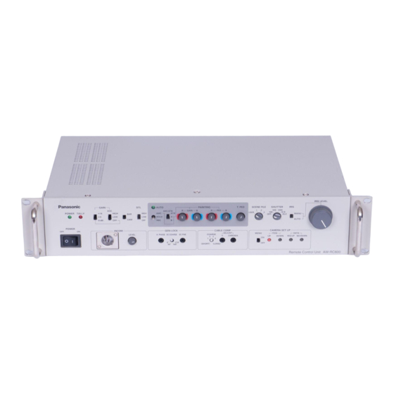
    Teile und ihre Funktionen Fronttafel  Netzschalter [POWER OFF/ON]  AGC-Wahlschalter [AGC HIGH/LOW/OFF] ON: In dieser Stellung wird das Gerät mit Strom HIGH: In dieser Stellung wird die maximale AGC- versorgt (die Betriebs-LED leuchtet auf). Verstärkung auf +30 dB gesetzt. (Dieser OFF: In dieser Stellung ist die Stromversorgung Wert kann je nach der verwendeten Kamera ausgeschaltet.
  • Seite 26 Teile und ihre Funktionen  Schalter für automatische  Weißabgleich-Wahlschalter Weiß-/Schwarzabgleicheinstellung [AWC/ATW ATW/A/B] [AWC/HOLD/ABC] Dieser Schalter dient zur Wahl der automatischen Weißabgleicheinstellung. Die automatische Einstellung des Weißabgleichs beginnt, ATW: In dieser Stellung liefert die Kamera eine wenn dieser Schalter auf die obere Position gestellt wird, Kompensation dahingehend, dass der während sich der Weißabgleich-Wahlschalter ...
  • Seite 27 Teile und ihre Funktionen  Rot- und Blauwertregler [PAINTING PED R/B]  Elektronikverschluss-Wahlschalter [SHUTTER OFF/120/500/1000/ S/S /ELC] Diese Regler ermöglichen eine Feineinstellung des Schwarzabgleichs. Dieser Schalter gestattet die Wahl der Verschlusszeit Wenn der Schwarzabgleich nach der Feineinstellung (OFF, 1/120, 1/500, 1/1000) sowie von S/S und ELC. erneut automatisch eingestellt wird, erfolgt eine S/S: Diese Abkürzung steht für Synchro Scan.
  • Seite 28 Teile und ihre Funktionen  Objektivblenden-Wahlschalter  Intercombuchse [INCOM] [IRIS MANU/AUTO] (4-polige XLR-Buchse) Die Blendenautomatik (ALC) des Objektivs wird An diese Buchse wird eine Kopfgarnitur angeschlossen. aktiviert, wenn dieser Schalter auf [AUTO] gestellt wird, Interkommunikation ist dann zwischen Kamera, RCU und während sich der Blendenwahlschalter am Objektiv Live-Bildmischpult möglich.
  • Seite 29 Teile und ihre Funktionen  Horizontalphasenregler [H.PHASE]  Chromaverstärkungsregler [ADJUST CHROMA] Dieser Regler dient zur Einstellung der Horizontalphasen Dieser Regler dient zur Einstellung des der Genlock-Eingabe und der Videoausgabe, wenn zwei Chrominanzpegels der Video-Ausgangssignale oder mehr Kameras gleichzeitig verwendet werden. zur Anpassung an die Kabellänge.
  • Seite 30: Rückseite

    Teile und ihre Funktionen Rückseite  Kamerakabelbuchse [CAMERA]  Stellen Sie sicher, dass die Stifte LEFT und RIGHT (26-polige Buchse) nicht gleichzeitig mit dem Stift COMM verbunden werden. Hier wird das Kamerakabel (wie z.B. AW-CA50A26)  Ebenso dürfen auch die Stifte UP und DOWN, FAR angeschlossen.
  • Seite 31 Teile und ihre Funktionen  Videoausgangsbuchsen [VIDEO1, VIDEO2] Hinweis: Wenn die Ausgangsbuchsen RGB/Y, PR und PB/YC  Die Videosignale der Kamera nach der und die S-Videoeingangsbuchse  gleichzeitig Kabelkompensation werden von diesen Buchsen verwendet werden, wird der Pegel der Ausgangssignale ausgegeben.
  • Seite 32: Anschlüsse

    Anschlüsse  Vergewissern Sie sich vor der Herstellung der Verbindungen, dass alle Geräte ausgeschaltet sind.  Verwenden Sie unbedingt das RCU-Kabel AW-CA50A26, um das RCU mit der Kamera zu verbinden.  Wenn die Kabelverbindung verlängert werden muss, verwenden Sie das Studio-Verlängerungskabel (WV-CA26U15, WV-CA26U30 oder WV-CA26U100) und den Verlängerungs-Verbindungsstecker (WV-CA26T26).
  • Seite 33: Bedienungsverfahren

    Bedienungsverfahren 1. Schalten Sie das Gerät ein. Stellen Sie den Schalter POWER des Gerätes auf [ON]. Netzschalter 2. Führen Sie die Kabelkompensations- und Genlock-Einstellungen durch. Genlock-Einstellung Kabelkompensation 3. Stellen Sie den Weißabgleich ein.  Diese Einstellung muss durchgeführt werden, wenn das Gerät zum ersten Mal benutzt wird oder längere Zeit nicht benutzt worden ist.
  • Seite 34: Einstellung

    Einstellung Kabelkompensation 1. Stellen Sie den Kabelkompensations-Wahlschalter auf die Position, die der Länge des Kabels zwischen Kamera und RCU entspricht. Schalterstellung Kabellänge Weniger als 75 m 75 bis 150 m 150 bis 230 m 230 bis 300 m (Die obigen Kabellängen sind Näherungswerte.) 2.
  • Seite 35: Weißabgleich-Einstellung

    Einstellung Weißabgleich-Einstellung  Automatische Einstellung (AWC)  Zwei Sätze von Farbtemperaturbedingungen können gespeichert werden.  Entsprechen die Benutzungsbedingungen des Gerätes den gespeicherten Werten, erübrigt sich eine Neueinstellung des Weißabgleichs.  Wenn eine automatische Neueinstellung des Weißabgleichs durchgeführt wird, werden die Daten im Speicher überschrieben.
  • Seite 36: Schwarzabgleich-Einstellung

    Einstellung Schwarzabgleich-Einstellung  Automatische Einstellung (ABC) 1. Der Schwarzabgleich kann automatisch eingestellt werden, indem der Schalter für automatische Weiß-/Schwarzabgleicheinstellung auf [ABC] gestellt wird. Während der automatischen Schwarzabgleicheinstellung beginnt die Automatik-LED zu blinken; sie erlischt, wenn die Einstellung erfolgreich ist und leuchtet auf, wenn sie nicht erfolgreich ist. Falls die Einstellung nicht erfolgreich war, versuchen Sie eine erneute automatische Einstellung.
  • Seite 37: Genlock-Einstellung

    Einstellung Genlock-Einstellung Wenn die Genlock-Funktion verwendet wird, müssen die Phasen der Signale eingestellt werden, um sie in Übereinstimmung mit den anderen Geräten und der Kamera zu bringen. Bevor Sie mit der Einstellung beginnen, schalten Sie die Videosignale der Kamera auf Farbbalkensignale um. ...
  • Seite 38: Einstellung Von Menüposten

    Einstellung von Menüposten Die konvertierbare Kamera wurde vor dem Versand im Herstellungswerk einer Voreinstellung unterzogen. Die Menüposten können jedoch für jeden Modus eingestellt oder geändert werden, um sie den tatsächlichen Aufnahmebedingungen anzupassen. Einzelheiten entnehmen Sie bitte der Bedienungsanleitung der Kamera. ...
  • Seite 39: Rack-Einbauwinkel

    Rack-einbau Wenn diese Einheit in ein 19-Zoll EIA-Rack eingebaut werden soll, die Rack-Einbauwinkel (mitgeliefert) und vier Befestigungsschrauben (M410) (mitgeliefert) verwenden. 1. Den Storm-EIN\AUS-Schalter dieser Einheit ausschalten. 2. Die vier Befestigungsschrauben der Gummifüße entfernen und die Gummifüße von der Unterseite der Einheit abnehmen.
  • Seite 40 Aussehen Einheit: mm 19 (G)
  • Seite 41: Technische Daten

    Technische Daten Stromversorgung: 220 bis 240 V Wechselstrom, 50 Hz Leistungsaufnahme: ca. 67 W ist die Sicherheitsinformation. Videoausgang: Composite-Signal 1,0 Vs-s/752 (BNC-Buchse) R/G/B-, Y/PR/PB-, Y/C-Signal (Schalter)je 1 (BNC-Buchse) R, B: 0,7 Vs-s/75, G: 1,0 Vs-s/75 (mit SYNC) Y: 1,0 Vs-s/75, PR, PB: 0,525 Vs-s/75 Y: 1,0 Vs-s/75, C: 0,3 Vs-s/75...
  • Seite 42: Consignes De Sécurité

    VERSION FRANÇAISE (FRENCH VERSION) Consignes de sécurité  Ne pas dévisser le couvercle. AVERTISSEMENT: Pour réduire tout risque d’électrocution, ne pas retirer POUR ÉVITER TOUT RISQUE le couvercle. Il ne se trouve à l’intérieur aucune pièce BLESSURES, L’APPAREIL DOIT ÊTRE qui puisse être réparée par l’utilisateur.
  • Seite 43 Table des matières Introduction ............... 2 Réglages ................13 Compensation de câble ..........13 Accessoires ..............2 Réglage de la balance des blancs ........ 14 Précautions d’utilisation ..........3 Réglage de la balance des noirs ........15 Les commandes et leurs fonctions ........ 4 Réglage du genlock ............
  • Seite 44: Précautions D'utilisation

    Précautions d’utilisation  Manipuler l’appareil avec précaution. Ne pas faire tomber l’appareil ni le soumettre à un choc puissant car cela risque de provoquer des dysfonctionnements ou des accidents.  Utiliser l’appareil dans une plage de températures située entre –10°C et +45°C. Le fait de l’utiliser dans un endroit exposé...
  • Seite 45: Les Commandes Et Leurs Fonctions

    Les commandes et leurs fonctions Façade  Interrupteur d’alimentation [POWER OFF/ON]  Sélecteur AGC [AGC HIGH/LOW/OFF] ON: Quand l’interrupteur est sur cette position, HIGH: Sur cette position, le gain AGC maximum est fixé l’appareil est alimenté (et la diode témoin à...
  • Seite 46 Les commandes et leurs fonctions  Commutateur de réglage de blanc automatique/  Sélecteur de balance des blancs noir automatique [AWC/HOLD/ABC] [AWC/ATW ATW/A/B] Le réglage automatique de la balance des blancs Ce sélecteur sert à sélectionner le réglage de balance commence quand ce commutateur est poussé...
  • Seite 47 Les commandes et leurs fonctions  Commandes de réglage de niveau de noir pour  Sélecteur d’obturateur électronique le rouge et le bleu [PAINTING PED R/B] [SHUTTER OFF/120/500/1000/ S/S /ELC] Ces commandes permettent d’ajuster finement la Ce sélecteur sert à sélectionner la vitesse d’obturation balance des noirs.
  • Seite 48 Les commandes et leurs fonctions  Sélecteur de diaphragme [IRIS MANU/AUTO]  Connecteur Intercom [INCOM] (connecteur XLR 4 broches) L’objectif est en mode diaphragme automatique (ALC) si ce sélecteur est positionné sur [AUTO] et que le sélecteur Ce connecteur sert à raccorder un casque. de diaphragme sur l’objectif est positionné...
  • Seite 49 Les commandes et leurs fonctions  Commande de réglage de phase horizontale  Commande de réglage de gain de chroma [H.PHASE] [ADJUST CHROMA] Cette commande sert à régler la phase horizontale de Cette commande sert à régler le niveau de chrominance l’entrée de verrouillage de synchronisation (genlock) et des signaux vidéo sortant en fonction de la longueur de la sortie vidéo quand plusieurs caméras sont utilisées...
  • Seite 50: Face Arrière

    Les commandes et leurs fonctions Face arrière  Connecteur de câble de caméra [CAMERA]  S’assurer que les broches LEFT et RIGHT ne sont pas (connecteur 26 broches) raccordées à la broche COMM en même temps.  De la même manière, ne pas raccorder les broches UP Le câble de caméra (tel que l’AW-CA50A26) est connecté...
  • Seite 51 Les commandes et leurs fonctions  Connecteur de sortie vidéo [VIDEO1, VIDEO2]  Connecteur d’entrée/sortie Tally/Intercom [TALLY/INCOM] (connecteur D-SUB 15 broches) Les signaux vidéo de la caméra après compensation de câble sortent de ces connecteurs. (Le même signal sort Le raccorder au connecteur TALLY & INCOM du module des connecteurs 1 et 2.) de commutation en direct (AW-SW350).
  • Seite 52: Raccordements

    Raccordements  Avant d’effectuer les branchements, s’assurer que tous les dispositifs sont hors tension.  Le câble servant à raccorder la RCU à la caméra doit impérativement être l’AW-CA50A26 RCU.  Pour allonger le câble, utiliser un câble de studio (WV-CA26U15, WV-CA26U30 ou WV-CA26U100) et un adaptateur de raccordement de câble (WV-CA26T26).
  • Seite 53: Utilisation

    Utilisation 1. Mettre sous tension. Positionner l’interrupteur d’alimentation de l’appareil sur [ON]. Interrupteur d’alimentation 2. Procéder aux réglages de compensation de câble et de verrouillage de synchronisation. Réglage du genlock Compensation de câble 3. Régler la balance des blancs.  Ce réglage doit être effectué quand l’appareil est utilisé pour la première fois ou s’il n’a pas été utilisé pendant une période prolongée.
  • Seite 54: Réglages

    Réglages Compensation de câble 1. Tourner le sélecteur de compensation de câble en fonction de la longueur du câble entre la caméra et la RCU. Position du sélecteur Longueur du câble Inférieure à 75 m 75 à 150 m 150 à 230 m 230 à...
  • Seite 55: Réglage De La Balance Des Blancs

    Réglages Réglage de la balance des blancs  Réglage automatique (AWC)  Deux ensembles de conditions de température de couleur peuvent être sauvegardés en mémoire.  Si l’appareil est utilisé dans les mêmes conditions que celles qui sont en mémoire, il n’est pas nécessaire de refaire le réglage de la balance des blancs.
  • Seite 56: Réglage De La Balance Des Noirs

    Réglages Réglage de la balance des noirs  Réglage automatique (ABC) 1. Pour régler la balance des noirs automatiquement, positionner le commutateur de réglage de blanc automatique/ noir automatique sur [ABC]. Pendant que la balance des noirs est ajustée automatiquement, la diode témoin de réglage automatique clignote: elle s’éteint si le réglage est réussi et reste allumée dans le cas opposé.
  • Seite 57: Réglage Du Genlock

    Réglages Réglage du genlock Quand la fonction de verrouillage de synchronisation est utilisée, les phases des signaux doivent être calées sur celles des autres dispositifs et de la caméra. Avant de procéder à ce réglage, commuter les signaux vidéo de la caméra sur les signaux de mire de couleur. ...
  • Seite 58: Réglage Des Options Du Menu

    Réglage des options du menu Les réglages de la caméra convertible ont été préréglés au moment de l’expédition de la caméra depuis l’usine. Il est cependant possible de régler ou de modifier les réglages des options du menu pour chaque mode en fonction des conditions de prise de vues.
  • Seite 59: Cornières D'installation En Rack

    Installation en rack Lorsque l’unité de commande à distance AW-RC600 doite être installée dans un meuble rack de 19 pouces, se servir des cornières d’installation en rack (fournies) et des quartre vis de montage (M410) (fournies). 1. Couper l’alimentation à l’aide de l’interrupteur d’alimentation de l’appareil. 2.
  • Seite 60: Aspect Extérieur

    Aspect extérieur Unité: mm 19 (F)
  • Seite 61: Fiche Technique

    Fiche technique Alimentation: 220 à 240 V CA, 50 Hz Consommation: environ 67 W Informations concernant la sécurité. Sortie vidéo: Signal composite 1,0 Vc-c/752 (connecteur BNC) Signal R/G/B, Y/PR/PB, Y/C (commutation)1 de chaque (connecteur BNC) R, B: 0,7 Vc-c/75, G: 1,0 Vc-c/75 (avec SYNC) Y: 1,0 Vc-c/75, PR, PB: 0,525 Vc-c/75...
  • Seite 62: Precauzioni Per La Sicurezza

    VERSIONE ITALIANA (ITALIAN VERSION) Precauzioni per la sicurezza  NON TOGLIERE IL COPERCHIO SVITANDOLO. ATTENZIONE: Per ridurre i pericoli di scosse elettriche, non togliere il PREVENIRE FERITE, QUESTO coperchio. All’interno non ci sono parti riparabili APPARECCHIO DEVE ESSERE MONTATO dall’utente. Per le riparazioni, rivolgersi a personale tecnico SALDAMENTE PAVIMENTO/MURO...
  • Seite 63 Sommario Introduzione ..............2 Regolazioni ..............13 Compensazione del cavo ..........13 Accessori ................2 Regolazione del bilanciamento del bianco ....14 Precauzioni per l’uso ............3 Regolazione del bilanciamento del nero ....... 15 Parti e loro funzioni ............4 Regolazione del genlock ..........
  • Seite 64: Precauzioni Per L'uso

    Precauzioni per l’uso  Maneggiare l’unità con attenzione. Se le unità cadono o se vengono assoggettate a forti urti, possono funzionare non correttamente o provocare incidenti.  Utilizzare l’unità a una temperatura compresa tra –10°C e +45°C. Se la temperatura non è compresa nel suddetto intervallo, i componenti interni potrebbero danneggiarsi. ...
  • Seite 65: Parti E Loro Funzioni

    Parti e loro funzioni Pannello anteriore  Interruttore di accensione [POWER OFF/ON]  Selettore AGC [AGC HIGH/LOW/OFF] ON: In questa posizione, l’unità viene alimentata (e HIGH: In questa posizione, il guadagno AGC massimo è l’indicatore LED di alimentazione si accende). impostato a +30 dB (questo valore può...
  • Seite 66 Parti e loro funzioni  Interruttore bilanciamento automatico del  Selettore bilanciamento del bianco bianco/nero [AWC/HOLD/ABC] [AWC/ATW ATW/A/B] Se il selettore bilanciamento del bianco  è in posizione Seleziona la configurazione del bilanciamento automatico [A] o [B] e questo interruttore è in posizione superiore, del bianco.
  • Seite 67 Parti e loro funzioni  Comandi di regolazione del livello di  Selettore otturatore elettronico spegnimento rosso e blu [PAINTING PED R/B] [SHUTTER OFF/120/500/1000/ S/S /ELC] Permettono di regolare di precisione il bilanciamento del Permette di selezionare la velocità dell’otturatore (OFF, nero.
  • Seite 68 Parti e loro funzioni  Selettore diaframma obiettiv [IRIS MANU/AUTO]  Connettore Intercom [INCOM] (connettore XLR 4 pin) Se il selettore è su [AUTO] mentre il selettore del diaframma è su [AUTO], sull’obiettivo viene attivato Viene utilizzato per collegare le cuffie. È quindi possibile il diaframma automatico (ALC).
  • Seite 69 Parti e loro funzioni  Comando di regolazione della fase orizzontale  Comando di regolazione guadagno crominanza [H.PHASE] [ADJUST CHROMA] Regola la fase orizzontale dell’ingresso genlock e Regola il livello di crominanza dei segnali di uscita video dell’uscita video se si utilizzano contemporaneamente a seconda della lunghezza del cavo.
  • Seite 70: Pannello Posteriore

    Parti e loro funzioni Pannello posteriore  Connettore cavo videocamer [CAMERA]  Verificare che i pin LEFT e RIGHT non siano collegati (connettore a 26 pin) al pin COMM contemporaneamente.  Allo stesso modo, non collegare i pin UP e DOWN, Viene utilizzato per collegare il cavo della videocamera FAR e NEAR o WIDE e TELE al pin COMM (es.
  • Seite 71 Parti e loro funzioni  Connettori uscita video [VIDEO1, VIDEO2] Pertanto, utilizzare i connettori  o  a seconda dei connettori utilizzati sul dispositivo collegato all’unità di Questi connettori trasmettono i segnali video della comando a distanza. videocamera dopo la compensazione del cavo. (I connettori 1 e 2 trasmettono lo stesso segnale.) ...
  • Seite 72: Collegamenti

    Collegamenti  Prima di procedere con i collegamenti, verificare che tutti i dispositivi siano scollegati dalla rete elettrica.  Verificare che per il collegamento tra RCU e videocamera venga utilizzato esclusivamente il cavo AW-CA50A26 RCU.  Per prolungare il cavo, utilizzare il cavo studio per estensione (WV-CA26U15, WV-CA26U30 o WV-CA26U100) e il connettore di giunzione (WV-CA26T26).
  • Seite 73 Funzionamento 1. Accendere l’unità. Posizionare l’interruttore di alimentazione su [ON]. Interruttore di accensione 2. Regolare la compensazione del cavo e il genlock. Regolazione del genlock Compensazione del cavo 3. Regolare il bilanciamento del bianco.  Questa regolazione deve essere effettuata se l’unità viene utilizzata per la prima volta o se è rimasta inutilizzata a lungo. ...
  • Seite 74: Regolazioni

    Regolazioni Compensazione del cavo 1. Spostare il selettore di compensazione del cavo in base alla lunghezza del cavo di collegamento tra videocamera e RCU. Posizione selettore Lunghezza cavo Meno di 75 m 75 – 150 m 150 – 230 m 230 –...
  • Seite 75: Regolazione Del Bilanciamento Del Bianco

    Regolazioni Regolazione del bilanciamento del bianco  Regolazione automatica (AWC)  È possibile memorizzare due set di temperature colore.  Se si utilizza l’unità alle stesse condizioni presenti in memoria, non è necessario regolare nuovamente il bilanciamento del bianco.  Regolando nuovamente il bilanciamento del bianco in modo automatico, i dati in memoria vengono sovrascritti. Selettore bilanciamento del bianco L’oggetto bianco deve occupare Indicatore LED...
  • Seite 76: Regolazione Del Bilanciamento Del Nero

    Regolazioni Regolazione del bilanciamento del nero  Regolazione automatica (ABC) 1. Il bilanciamento del nero può essere regolato automaticamente spostando l’interruttore bilanciamento automatico del bianco/nero su [ABC]. Durante la regolazione automatica del bilanciamento del nero, l’indicatore LED impostazione automatica lampeggia. Se la regolazione si conclude con successo, l’indicatore si spegne, mentre rimane acceso in caso di insuccesso.
  • Seite 77: Regolazione Del Genlock

    Regolazioni Regolazione del genlock Se si utilizza la funzione genlock, le fasi dei segnali devono essere regolate e allineate con gli altri dispositivi e la videocamera. Prima di procedere con la regolazione, commutare il segnali video della videocamera in segnali di barre dei colori. ...
  • Seite 78: Configurazione Delle Voci Di Menu

    Configurazione delle voci di menu Le impostazioni della videocamera convertibile sono state predefinite in fabbrica. Tuttavia, le voci di menu possono essere configurate o modificate per ogni modalità a seconda delle condizioni di ripresa. (per maggiori informazioni, consultare il manuale di funzionamento della videocamera). ...
  • Seite 79: Angolari Di Montaggio Su Rack

    Montaggio su rack Se si intende montare questa unità su un rack EIA di 19 poillici, usare gli angolari di montaggio su rack (in dotazione) e quattro viti di montaggio (M410) (in dotazione). 1. Spegnere l’unità mediante l’interruttore di alimentazione (POWER). 2.
  • Seite 80: Aspetto

    Aspetto Unità: mm 19 ( I )
  • Seite 81: Dati Tecnici

    Dati tecnici Alimentazione: C.a. 220 - 240 V, 50 Hz Assorbimento di corrente: 67 W circa sono le informazioni sulla sicurezza. Uscita video: Segnale composito 1,0 Vp-p/ 752 (connettore BNC) Segnale R/G/B, Y/PR/PB, Y/C (interruttore), uno per ognuno (connettore BNC) R,B: 0,7 Vp-p/75, G: 1,0 Vp-p/75...
  • Seite 82: Precauciones De Seguridad

    VERSIÓN ESPAÑOLA (SPANISH VERSION) Precauciones de seguridad  NO QUITE LA CUBIERTA DESATORNILLÁNDOLA. ADVERTENCIA: No quite la tapa para evitar el riesgo de sacudidas PARA EVITAR HERIDAS, ESTE APARATO eléctricas. Las piezas del interior no requieren DEBE ESTAR FIRMEMENTE INSTALADO AL mantenimiento por parte del usuario.
  • Seite 83: Introducción

    Índice Introducción ..............2 Ajuste ................13 Compensación de cable ..........13 Accesorios ................ 2 Ajuste del balance del blanco ........14 Precauciones para la utilización ........3 Ajuste del balance del negro ......... 15 Partes y sus funciones ............ 4 Ajuste del intersincronizador .........
  • Seite 84: Precauciones Para La Utilización

    Precauciones para la utilización  Manipule la unidad cuidadosamente. Si se cae la unidad o recibe un golpe fuerte puede provocar una avería o accidente.  Utilice la unidad dentro de un margen de temperaturas de –10°C a +45°C. El funcionamiento en lugares donde la temperatura sea inferior a –10°C o superior a +45°C podrá afectar adversamente a las piezas internas.
  • Seite 85: Partes Y Sus Funciones

    Partes y sus funciones Panel frontal  Interruptor de la alimentación [POWER OFF/ON]  Conmutador selector AGC ON: En esta posición se suministra alimentación [AGC HIGH/LOW/OFF] eléctrica a la unidad (y el LED indicador de la HIGH: En esta posición, la ganancia máxima de AGC alimentación se enciende).
  • Seite 86 Partes y sus funciones  Conmutador de ajuste automático del blanco/  Conmutador selector del balance del blanco negro [AWC/HOLD/ABC] [AWC/ATW ATW/A/B] El ajuste automático del balance del blanco empieza al Este conmutador se utiliza para seleccionar el ajuste del poner este conmutador en la posición superior mientras balance del blanco.
  • Seite 87 Partes y sus funciones  Controles de ajuste de pedestal del rojo y del  Conmutador selector de obturador electrónico azul [PAINTING PED R/B] [SHUTTER OFF/120/500/1000/ S/S /ELC] Estos controles permiten ajustar con precisión el balance Este conmutador permite elegir la velocidad del del negro.
  • Seite 88 Partes y sus funciones  Conmutador selector del iris del objetivo  Conector de intercomunicación [INCOM] [IRIS MANU/AUTO] (Conector XLR de 4 contactos) El objetivo se pone en el modo de iris automático (ALC) Aquí se puede conectar un auricular. Y la si este conmutador se pone en [AUTO] cuando el intercomunicación se puede realizar entonces entre la conmutador selector del iris del objetivo está...
  • Seite 89 Partes y sus funciones  Control de ajuste de fase horizontal [H.PHASE]  Control de ajuste de ganancia de croma Este control se utiliza para ajustar las fases horizontales [ADJUST CHROMA] de la entrada del sincronizador de señales de vídeo y de Este control se utiliza para ajustar el nivel de crominancia la salida de vídeo cuando se utilizan dos o más cámaras de las señales de salida de vídeo de forma que...
  • Seite 90: Panel Trasero

    Partes y sus funciones Panel trasero  Conector de cable de cámara [CAMERA]  Asegúrese de que los contactos LEFT y RIGHT no (Conector de 26 contactos) estén conectados al contacto COMM al mismo tiempo. El cable de la cámara (como el AW-CA50A26) se ...
  • Seite 91 Partes y sus funciones  Conectores de salida de vídeo Nota: [VIDEO1, VIDEO2] Cuando los conectores de salida RGB/Y, PR y PB/YC  y el conector de salida de S-Vídeo  se utilicen al mismo Las señales de vídeo procedentes de la cámara después tiempo, el nivel de las señales de salida se reducirá.
  • Seite 92: Conexiones

    Conexiones  Antes de hacer las conexiones, asegúrese de que la alimentación de todos los dispositivos esté desconectada.  Asegúrese de utilizar el cable de RCU AW-CA50A26 para conectar la RCU a la cámara.  Cuando extienda el cable, utilice el cable de estudio de extensión (WV-CA26U15, WV-CA26U30 ó WV-CA26U100) y el conector de unión de extensión (WV-CA26T26).
  • Seite 93: Procedimiento De Operación

    Procedimiento de operación 1. Conecte la alimentación. Ponga el interruptor de la alimentación de la unidad en [ON]. Interruptor de la alimentación 2. Haga los ajustes de compensación de cable y del sincronizador de señales de vídeo. Ajuste del intersincronizador Compensación de cable 3.
  • Seite 94: Ajuste

    Ajuste Compensación de cable 1. Ponga el conmutador selector de compensación de cable en la posición correspondiente a la longitud del cable que va a conectar la cámara y la RCU. Posición del conmutador Longitud del cable Menos de 75 m 75 a 150 m 150 a 230 m 230 a 300 m...
  • Seite 95: Ajuste Del Balance Del Blanco

    Ajuste Ajuste del balance del blanco  Ajuste automático (AWC)  En la memoria se pueden guardar dos juegos de condiciones de temperaturas del color.  Cuando se utilice la unidad bajo las mismas condiciones que las que se encuentran guardadas en la memoria, no será necesario volver a ajustar el balance del blanco.
  • Seite 96: Ajuste Del Balance Del Negro

    Ajuste Ajuste del balance del negro  Ajuste automático (ABC) 1. El balance del negro se puede ajustar automáticamente poniendo el conmutador de ajuste automático del blanco/ negro en la posición [ABC]. Mientras el balance del negro está siendo ajustado automáticamente, el LED indicador de ajuste automático empezará a parpadear: se apaga si el ajuste se realiza correctamente y se enciende en caso contrario.
  • Seite 97: Ajuste Del Intersincronizador

    Ajuste Ajuste del intersincronizador Cuando utilice la función del sincronizador de señales de vídeo, las fases de las señales deberán ajustarse para alinear las fases con los otros dispositivos y la cámara. Antes de hacer el ajuste, cambie las señales de vídeo de la cámara a las señales de franjas de colores. ...
  • Seite 98: Ajuste De Los Elementos Del Menú

    Ajuste de los elementos del menú Los ajustes de la cámara convertible fueron preestablecidos antes de salir la cámara de la fábrica. Sin embargo, los elementos del menú se pueden establecer o cambiar para cada modo y adaptarlos a las condiciones de la filmación real. Para conocer detalles, consulte las instrucciones de funcionamiento de la cámara.
  • Seite 99: Montaje En Estantería

    Montaje en estantería Cuando la unidad vaya a montarse en una estantería EIA de unos 19-inch, utilice las piezas angulares de montaje en estantería (suministradas) y cuatro tornillos de montaje (M410) (suministrados). 1. Desconecte la alimentación de la unidad. 2. Quite los cuatro tornillos de fijación de las patas de goma y retire las cuatro patas de goma del fondo de la unidad. Quite las patas de goma.
  • Seite 100: Apariencia

    Apariencia Unidad: mm 19 (S)
  • Seite 101: Especificaciones

    Especificaciones Alimentación: 220 V a 240 V CA, 50 Hz Consumo: 67 W aproximadamente indica información de seguridad. Salida de vídeo: Señal de vídeo compuesto, 1,0 Vp-p/752 (Conector BNC) Señales R/G/B, Y/PR/PB, Y/C (conmutables)1 conector (Conector BNC) R, B: 0,7 Vp-p/75, G: 1,0 Vp-p/75 (con SYNC) Y: 1,0 Vp-p/75, PR, PB: 0,525 Vp-p/75...
  • Seite 102: Русская Версия

    РУССКАЯ ВЕРСИЯ (RUSSIAN VERSION) Меры предосторожности  НЕ ОТВИНЧИВАЙТЕ КРЫШКИ ПАНЕЛЕЙ. ВНИМАНИЕ: Для снижения риска удара электрическим током не снимайте ВО ИЗБЕЖАНИЕ ПОВРЕЖДЕНИЯ ДАННЫЙ ПРИБОР панели. Внутри устройства нет деталей, подлежащих ДОЛЖЕН БЫТЬ НАДЕЖНО ЗАКРЕПЛЕН НА ПОЛУ/СТЕНЕ В обслуживанию пользователем. СООТВЕТСТВИИ...
  • Seite 103 Содержание Введение ................2 Регулировка ................ 13 Компенсация кабеля ............13 Принадлежности ..............2 Регулировка баланса белого ..........14 Меры предосторожности во время использования ....3 Регулировка баланса черного ..........15 Компоненты и их функции ............4 Регулировка синхронизатора видеосигналов ......16 Передняя...
  • Seite 104: Меры Предосторожности Во Время Использования

    Меры предосторожности во время использования  Обращайтесь с устройством осторожно. Если устройство бросать или подвергать его сильному ударному воздействию, это может привести к возникновению неисправности или несчастному случаю.  Эксплуатируйте устройство в температурном диапазоне от –10°C до +45°C. Эксплуатация при температуре ниже –10°C или выше +45°C может неблагоприятно повлиять на внутренние компоненты. ...
  • Seite 105: Компоненты И Их Функции

    Компоненты и их функции Передняя панель  Выключатель питания [POWER OFF/ON]  Селекторный переключатель автоматической В этом положении на устройство подается электропитание регулировки усиления [AGC HIGH/LOW/OFF] (светодиод индикатора питания загорается). HIGH: При выборе данного значения максимальное усиление OFF: В этом положении электропитание отключается. автоматической...
  • Seite 106 Компоненты и их функции  Переключатель установки автоматического баланса  Селекторный переключатель баланса белого белого/черного [AWC/HOLD/ABC] [AWC/ATW ATW/A/B] Если данный переключатель установлен в верхнее положение, Данный переключатель используется для выбора установки а селекторный переключатель баланса белого  находится в автоматического баланса белого. положении...
  • Seite 107 Компоненты и их функции  Регуляторы уровня гашения красного и синего  Селекторный переключатель электронного затвора [PAINTING PED R/B] [SHUTTER OFF/120/500/1000/ S/S /ELC] Данные регуляторы позволяют выполнять точную регулировку Данный переключатель позволяет выбирать выдержку затвора баланса черного. (OFF, 1/120, 1/500, 1/1000), а также значения S/S и ELC. При...
  • Seite 108 Компоненты и их функции  Селекторный переключатель диафрагмы объектива  Разъем двусторонней связи [INCOM] [IRIS MANU/AUTO] (4-штырьковый разъем XLR) Если селекторный переключатель диафрагмы на объективе Сюда подключается гарнитура. После подключения возможна установлен в положение [AUTO], а данный переключатель также двусторонная связь между камерой, БДУ и видеомикшером установлен...
  • Seite 109 Компоненты и их функции  Регулятор фазы по строкам [H.PHASE]  Регулятор усиления уровня сигнала цветности Используется для регулировки фаз по строкам входного [ADJUST CHROMA] синхронизирующего сигнала и выходного видеосигнала при Используется для регулировки уровня насыщенности изображения одновременном использовании двух или более камер. выходных...
  • Seite 110: Задняя Панель

    Компоненты и их функции Задняя панель  Разъем кабеля камеры [CAMERA]  Убедитесь, что оба штырька LEFT и RIGHT не подключены к (26-штырьковый разъем) штырьку COMM одновременно.  Так же, не подключайте к штырьку COMM одновременно К данному разъему подключается кабель камеры (такой, как штырьки...
  • Seite 111 Компоненты и их функции  Разъемы выходного видеосигнала [VIDEO1, VIDEO2]  Входной/выходной разъем сигнала/двусторонней связи С данных разъемов подаются видеосигналы с камеры после [TALLY/INCOM] (15-штырьковый разъем D-SUB) компенсации кабеля. (С разъемов 1 и 2 выводится один и тот Подключайте данный разъем к разъему сигнала/двусторонней же...
  • Seite 112 Соединения  Перед продолжением подключения убедитесь, что питание всех устройств отключено.  Не забудьте проверит, что для подключения БДУ к камере используется кабель AW-CA50A26.  При удлинени кабеля используйте удлиняемый студийный кабель (WV-CA26U15, WV-CA26U30 или WV-CA26U100) и соединительный разъем для расширения...
  • Seite 113: Рабочая Процедура

    Рабочая процедура 1. Включите электропитание. Установите выключатель электропитания устройства в положение [ON]. Выключатель питания 2. Перейдите к регулировкам компенсации кабеля и принудительной синхронизации. Регулировка синхронизатора видеосигналов Компенсация кабеля 3. Отрегулируйте баланс белого.  Данную регулировку следует выполнять, если устройство используется в первый раз или если устройство не использовалось в течение длительного...
  • Seite 114 Регулировка Компенсация кабеля 1. Поворачивайте селекторный переключатель компенсации кабеля для соответствия длины кабеля, соединяющего камеру с БДУ. Положение переключателя Длина кабеля Менее 75 м От 75 до 150 м От 150 до 230 м От 230 до 300 м (Выше приведены приблизительные длины кабелей). 2.
  • Seite 115: Регулировка Баланса Белого

    Регулировка Регулировка баланса белого  Автоматическая регулировка (AWC)  В памяти можно сохранять два набора параметров цветовой температуры.  При использовании устройства в тех же условиях, которые сохранены в памяти, повторная регулировка баланса белого не требуется.  При повторном выполнении автоматической регулировки баланса белого данные в памяти обновляются. Селекторный...
  • Seite 116: Регулировка Баланса Черного

    Регулировка Регулировка баланса черного  Автоматическая регулировка (ABC) 1. Регулировка баланса черного может выполняться автоматически путем установки переключателя автоматического баланса белого/ черного в положение [ABC]. Во время выполнения автоматической регулировки баланса черного светодиодный индикатор автоматической установки начинает мигать; он гаснет, если регулировка завершилась успешно, и загорается, если регулировка не завершилась успешно. Если регулировка не завершилась успешно, попробуйте...
  • Seite 117: Регулировка Синхронизатора Видеосигналов

    Регулировка Регулировка синхронизатора видеосигналов При использовании функции принудительной синхронизации видеосигнала фазы сигналов должны быть отрегулированы для соответствия фаз камеры с другими устройствами. Перед продолжением регулировки переключите видеосигналы камеры на сигналы цветовых полос.  Регулировка фазы по строкам Наблюдая формы входного сигнала принудительной синхронизации при помощи двухсигнального электронно-лучевого осциллографа (сигналы черного...
  • Seite 118: Установка Пунктов Меню

    Установка пунктов меню Настройки стационарной камеры с дистанционным управлением установлены заранее при поставке камеры с завода-изготовителя. Тем не менее, значения параметров меню для каждого режима можно устанавливать или изменять для соответствия их фактическим условиям съемки. Для получения дополнительной информации обращайтесь к руководству по эксплуатации камеры. ...
  • Seite 119: Монтаж В Стойку

    Монтаж в стойку При монтаже устройства в 19-дюймовую стойку EIA используйте уголки для стоечного монтажа (прилагаются) и четыре крепежных винта (M410) (прилагаются). 1. Отключите выключатель питания устройства. 2. Отвинтите четыре винта, крепящие резиновые ножки, и снимите четыре резиновые ножки с нижней части устройства. Снимите...
  • Seite 120: Внешний Вид

    Внешний вид Единица измерения: мм 19 (R)
  • Seite 121: Технические Характеристики

    Технические характеристики Источник питания: От 220 до 240 В переменного тока, 50 Гц Потребляемая мощность: Приблиз. 67 Вт Данный знак обозначает информацию, относящуюся к технике безопасности. Выходной видеосигнал: Композитный сигнал, размах 1,0 В/752 (разъем BNC) Сигнал R/G/B, Y/PR/PB, Y/C (переключатель)1 каждый (разъем BNC) R,B: Размах...
  • Seite 124 Matsushita Electric Industrial Co., Ltd. Web Site: ht t p: // www.p a n a s o n i c. c o. j p / g l o b a l / Printed in Japan Gedruckt in Japan Imprimé au Japon Stampato in Giappone Impreso en Japón Напечатано...

Inhaltsverzeichnis