Mettler Toledo IND560 Installationsanleitung
Vorschau ausblenden
Andere Handbücher für IND560:
- Benutzerhandbuch (63 Seiten) ,
- Bedienungsanleitung (196 Seiten) ,
- Installationsanleitung (252 Seiten)

Verwandte Anleitungen für Mettler Toledo IND560


Inhaltszusammenfassung für Mettler Toledo IND560
- Seite 1 IND560 Terminal Installation Manual Guía de Instalación Installationsanleitung Guide d’installation Guida all’installazione www.mt.com 71209395 (08/2010).R06...
- Seite 2 IND560 Terminal Installation Manual...
- Seite 3 Restricted Rights. Copyright 2010 METTLER TOLEDO. This documentation contains proprietary information of METTLER TOLEDO. It may not be copied in whole or in part without the express written consent of METTLER TOLEDO. METTLER TOLEDO reserves the right to make refinements or changes to the product or manual without notice.
- Seite 4 NOTE ON FIRMWARE VERSIONS This manual describes features and functions of the IND560 terminal with version 4.xx firmware. Terminals with version 3.xx firmware or lower will differ in some areas. The following list indicates the key differences between versions: New in version 4.xx – optional USB host port; install, backup and restore software via USB;...
- Seite 5 DEMKO APPROVAL CERTIFICATE 06ATEX0514991X AND ALL LOCAL REGULATIONS MUST BE FOLLOWED WITHOUT EXCEPTION. FAILURE TO DO SO COULD RESULT IN BODILY HARM AND/OR PROPERTY DAMAGE. REFER TO THE IND560 DIVISION 2 AND ZONE 2/22 INSTALLATION GUIDE 64060405 FOR ADITIONAL INFORMATION. WARNING!
- Seite 6 HAZARDS INVOLVED. FAILURE TO OBSERVE THIS PRECAUTION COULD RESULT IN BODILY HARM AND/OR PROPERTY DAMAGE. WARNING! TO AVOID DAMAGE TO THE PCB OR LOAD CELL, REMOVE POWER FROM THE IND560 TERMINAL AND WAIT AT LEAST 30 SECONDS BEFORE CONNECTING OR DISCONNECTING ANY HARNESS.
- Seite 7 WARNING! ONLY THE COMPONENTS SPECIFIED IN THIS MANUAL CAN BE USED IN THIS TERMINAL. ALL EQUIPMENT MUST BE INSTALLED IN ACCORDANCE WITH THE INSTALLATION INSTRUCTIONS DETAILED IN THIS MANUAL. INCORRECT OR SUBSTITUTE COMPONENTS AND/OR DEVIATION FROM THESE INSTRUCTIONS CAN IMPAIR THE SAFETY OF THE TERMINAL AND COULD RESULT IN BODILY INJURY AND/OR PROPERTY DAMAGE.
- Seite 8 IND560 Terminal Essential Services for Dependable Performance Congratulations on choosing the quality and precision of METTLER TOLEDO. Proper use of your new equipment according to this Manual and regular calibration and maintenance by our factory-trained service team ensures dependable and accurate operation, protecting your investment.
-
Seite 9: Inhaltsverzeichnis
Contents Chapter 1.0 Introduction ........1-1 IND560 Overview............... 1-2 Standard IND560 Features..............1-2 IND560 Terminal Versions ............1-3 Specifications ................1-4 Environmental Protection............. 1-7 Safe Disposal Requirement ............1-7 Inspection and Contents Checklist ..........1-7 Model Identification ..............1-8 Physical Dimensions ..............1-9 Main PCB................ - Seite 10 IND560 Installation Manual PCB Jumper Positions .............. 2-32 Main PCB Jumper................2-32 Capacity Label Instructions ............2-33 Sealing the Enclosure ............... 2-34 External Sealing of the Panel-Mount Enclosure ........2-34 External Sealing of the Harsh Enclosure..........2-36 Internal Sealing of Both Enclosure Types..........2-36...
- Seite 11 Introduction DIV 2 AND ZONE 2/22 INSTALLATION IF YOU WISH TO INSTALL THE IND560 IN A DIVISION 2 OR ZONE 2/22 AREA, REFER TO THE DIVISION 2 AND ZONE 2/22 INSTALLATION INSTRUCTIONS INCLUDED ON THE DOCUMENTATION CD PROVIDED WITH THE TERMINAL. FAILURE TO COMPLY WITH THE INSTRUCTIONS PROVIDED THERE COULD RESULT IN BODILY HARM AND/OR PROPERTY DAMAGE.
-
Seite 12: Ind560 Overview
IND560 Installation Manual Whether communicating weight data to a process PLC or providing an easier way to do terminal configuration via the InSite™ PC Tool, the IND560 offers multiple connectivity options to improve applications. Direct PLC connectivity is available using 4-20mA Analog Output, Allen-Bradley RIO, PROFIBUS DP, DeviceNet, EtherNet/IP or Modbus TCP protocols. -
Seite 13: Ind560 Terminal Versions
COM-560 Dyn-560 Support for TaskExpert™ custom application development software • IND560 Terminal Versions The IND560 terminal is available in the following versions: Harsh enclosure with analog load cell connection • Harsh enclosure with high-precision (IDNet) base connection • Panel-mount enclosure with analog load cell connection •... -
Seite 14: Specifications
IND560 Installation Manual Specifications The IND560 terminal conforms to the specifications listed in Table 1-1. Table 1-1: IND560 Specifications IND560 Specifications Enclosure Type Panel-mount stainless steel front panel with an aluminum frame Harsh environment desk/wall/column-mount type 304L stainless steel enclosure Dimensions (l ×... - Seite 15 IND560 Installation Manual IND560 Specifications Display 128 × 64 dot-matrix graphic VFD display, 21 mm Display Update Rate: 10/second Weight Display Displayed resolution of 100,000 counts for analog load cell scales Display resolution for high-precision IDNet bases is determined by the specific base used...
- Seite 16 85 V/60 Hz 264 V/50 Hz 110 V/50 Hz 110 V/60 Hz 240 V/50 Hz 240 V/60 Hz Test condition: IND560 with internal Ethernet/Serial, Analog Output and Discrete I/O options installed, input loaded to simulate 8 x 350 load cells.
-
Seite 17: Environmental Protection
AREAS CLASSIFIED AS HAZARDOUS BY THE NATIONAL ELECTRICAL CODE (NEC) BECAUSE OF COMBUSTIBLE OR EXPLOSIVE ATMOSPHERES. When an approved IND560 is installed in an area classified as Division 2 or Zone 2/22, special AC wiring requirements must be met. See document 64060405, IND560 Division 2, Zone 2/22 Installation Guide. -
Seite 18: Model Identification
IND560 Installation Manual Model Identification The IND560 model number is located on the data plate on the back of the terminal along with the serial number. Refer to Figure 1-1 to verify the IND560 that was ordered. Figure 1-1: IND560 Model Identification Numbers... -
Seite 19: Physical Dimensions
IND560 Installation Manual Physical Dimensions The physical dimensions of the Panel Mount IND560 enclosure are shown in Figure 1-2 in inches and [mm]. Figure 1-3 shows the dimensions of the cutout required for the Panel Mount enclosure. Figure 1-2: IND560 Panel Mount Enclosure Dimensions... - Seite 20 IND560 Installation Manual The dimensions of the harsh enclosure desk/wall-mount IND560 terminal are shown in Figure 1-4 and Figure 1-5 in inches and [mm]. Figure 1-4: Harsh Environment Enclosure Dimensions Figure 1-5: Harsh Environment Enclosure Dimensions with Optional Brackets 1-10...
-
Seite 21: Main Pcb
The IND560 supports two types of scale bases: Analog or IDNet. Analog Load Cell Scale Base The IND560 supports this scale type by an analog load cell interface. The terminal can drive up to eight 350-ohm analog load cells. ™... -
Seite 22: Discrete I/O
WARNING THE INTERNAL #71209093 DISCRETE I/O RELAY OPTION MUST NOT BE USED IN AN IND560 TERMINAL INSTALLED IN AN AREA CLASSIFIED AS DIVISION 2 OR ZONE 2/22. FAILURE TO COMPLY WITH THIS WARNING COULD RESULT IN BODILY HARM AND/OR PROPERTY DAMAGE. -
Seite 23: Ethernet/Usb/Com3 Option
The IND560 PLC interface options include Analog Output, A-B RIO, DeviceNet, PROFIBUS DP, EtherNet/IP and Modbus TCP. Additional details about each of these interfaces can be found in the IND560 PLC Interface Manual, provided on the documentation CD. Analog Output Analog Output refers to the representation of an internal system variable using a proportional electrical signal. -
Seite 24: Devicenet
Maintenance, for details on performing a master reset. Fill-560 The Fill-560 is a special application that can be added to the IND560 terminal to provide additional filling and dosing control. It provides control for the following combinations of weigh-in and weigh-out sequences. - Seite 25 The IND560com maintains all of the standard features and functions of the IND560 in addition to the specific features and functions of the COM-560. It provides the following features and functions:...
-
Seite 26: Taskexpert
™ InSite Configuration Tool The IND560 terminal can connect to a PC running InSite via Ethernet or Serial to provide the following: • Viewing and/or changing configuration. • Enabling device-free configuration work before hardware installation. • Saving configuration information locally on the PC, loading a saved configuration file into other devices, or restoring to a known state for service purposes. -
Seite 27: Display And Keyboard
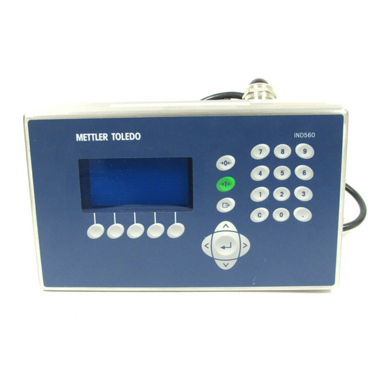
• Performing firmware upgrade services for the IND560. Display and Keyboard The IND560 terminal has a Vacuum Fluorescent Display (VFD), 128 × 64 dot matrix graphic type display. An example of the IND560 front panel is shown in Figure 1-6. Numeric keys... -
Seite 28: Front Panel Keys
IND560 Installation Manual Front Panel Keys Three dedicated scale function keys are located to the right of the display. These provide the interface to zero or tare the scale and to initiate a print. The terminal’s 12-key numeric keypad is used to enter data and commands. The numeric keys are located on the upper-right side of the terminal front panel. - Seite 29 Sealing the Enclosure DIV 2 AND ZONE 2/22 INSTALLATION IF YOU WISH TO INSTALL THE IND560 IN A DIVISION 2 OR ZONE 2/22 AREA, REFER TO THE DIVISION 2 AND ZONE 2/22 INSTALLATION INSTRUCTIONS INCLUDED ON THE RESOURCE CD PROVIDED WITH THE TERMINAL. FAILURE TO COMPLY WITH THE INSTRUCTIONS PROVIDED THERE COULD RESULT IN BODILY HARM AND/OR PROPERTY DAMAGE.
-
Seite 30: Opening The Enclosures
Figure 2-1: Opening the Panel-Mount Enclosure Harsh Enclosure The front panel of the harsh enclosure IND560 terminal is locked in place by four spring clips attached to the enclosure body. To gain access to the terminal’s PCB for internal wiring and setting switches, separate the front panel from the enclosure as follows: 1. -
Seite 31: Environmental Protection
Figure 2-3: Removing the Cover Environmental Protection WARNING! NOT ALL VERSIONS OF THE IND560 ARE DESIGNED FOR USE IN HAZARDOUS (EXPLOSIVE) AREAS. REFER TO THE DATA PLATE OF THE IND560 TO DETERMINE IF A SPECIFIC TERMINAL IS APPROVED FOR USE IN AN AREA CLASSIFIED AS HAZARDOUS BECAUSE OF COMBUSTIBLE OR EXPLOSIVE ATMOSPHERES. -
Seite 32: Mounting The Terminal
IND560 Installation Manual Mounting the Terminal The panel-mount enclosure is designed to mount into a cutout of a flat surface such as an instrument panel or industrial enclosure or door. The harsh enclosure is designed to be placed on a desktop or can be mounted to a vertical surface with the optional mounting brackets. -
Seite 33: Harsh Enclosure
NOTE: Once the Allen-head screws have been tightened, and the unit secured into place, the rear cover plate of the IND560 panel mount unit may be difficult to remove and replace for servicing. If this occurs, slight loosening of the Allen-head screws should allow for removal and replacement of the rear cover for service purposes. -
Seite 34: Desktop Mounting
IND560 Installation Manual Desktop Mounting When the IND560 terminal will be placed on a flat surface, the four rubber feet included with the terminal should be adhered to the bottom of the enclosure to prevent sliding. Locate the four rubber feet, remove the protective paper from the adhesive, and press the feet onto the corners of the bottom of the enclosure as shown in Figure 2-7. - Seite 35 IND560 Installation Manual A. Open the enclosure per the instructions provided in the Opening the Enclosures section. B. Loosen and remove the two nuts securing the two grounding straps (that also operate as hinges for the front cover) to the rear housing. See Figure 2-9.
-
Seite 36: Installing Cables And Connectors
Wiring Connections for Options Ferrites In order to meet certain electrical noise emission limits and to protect the IND560 from external influences, it is necessary to install a ferrite core on each cable connected to the terminal. There are two ferrite cores included with the basic terminal and additional ferrites are supplied with each of the options. -
Seite 37: Harsh Enclosure Cable Glands
Figure 2-12 : Installing the Ferrite Cores Harsh Enclosure Cable Glands The IND560 harsh environment terminal is designed to withstand severe washdown environments. However, care must be taken when installing cables and/or connectors that enter the terminal enclosure. To ensure a watertight seal: •... -
Seite 38: Main Board Wiring Connections
Figure 2-14: Cable Shield Grounding Main Board Wiring Connections Once the IND560 terminal harsh enclosure is open, connections can be made to the terminal strips on the main board, as shown in Figure 2-15. Load Cell COM1... -
Seite 39: Power Connection
A permanently attached line cord supplies the AC power to the harsh enclosure version of the IND560 terminal. The panel-mount enclosure does not provide an AC power cord—it is designed to have AC wiring brought directly to the rear of the chassis and connected to the AC power terminal strip. - Seite 40 TSR = Number of Load Cells Ensure that the TSR of the load cell network to be connected to the IND560 has a resistance greater than 43 ohms before connecting the load cells. If the resistance is less than 43 ohms, the IND560 will not operate properly.
- Seite 41 (+SIG and −SIG). IDNet Connections The IND560 terminal supplies 12 V for the new T-Brick type cell of the IDNet base. Some older types of bases (known as Pik-Brick) required both a 12 V and a 32 V supply.
- Seite 42 IND560 Installation Manual Figure 2-19: IDNet Connector Location on the Harsh Enclosure Figure 2-20 shows the pin assignments and wire colors for the IDNet connector. IDNet connector Color Note P1–A Green TXD+/RXD+ P1–B Blue +30V P1–C Grey +12V P1–D Green Jumper P1–E...
-
Seite 43: Wiring Connections For Options
120 ohms. This terminating resistor is required when connecting ARM100 modules to the port. Wiring Connections for Options Options available for the IND560 terminal that require external connections include the following: • Analog Output •... - Seite 44 IND560 Installation Manual • PROFIBUS (Harsh Enclosure) • PROFIBUS (Panel-Mount Enclosure) • Allen-Bradley (A-B) RIO • EtherNet/IP – Modbus TCP Figure 2-23 shows where each of these options is located in the harsh enclosure and Figure 2-24 shows where they are located in the panel-mount enclosure. The connections for each of these options are described in the following sections.
- Seite 45 IND560 Installation Manual Figure 2-24: Option Locations for Panel-Mount Enclosure 2-17...
-
Seite 46: Analog Output Connections
IND560 Installation Manual Analog Output Connections The analog output option board (Figure 2-25) fits into the PLC interface slot on the Main board. It provides either 0-10 VDC or 4-20mA (only one) analog signal proportional to the weight applied to the scale. - Seite 47 IND560 Installation Manual Ethernet, COM2, and COM3 Connections The Ethernet/TCP IP and dual COM port option board (Figure 2-27) is positioned in the center option slot on the Main board. This port provides a 10 Base-T connection (10 Mb) connection for Ethernet and two serial ports labeled COM2 and COM3.
- Seite 48 IND560 Installation Manual Ethernet, USB, COM3 Connections The Ethernet/USB/COM3 option board (Figure 2-27) can be positioned in the center option slot on the Main board. This option board provides a USB Master,10 Base-T connection (10 Mb) connection for Ethernet and a single serial port labeled COM3.
- Seite 49 IND560 Installation Manual Adhere Ethernet label here Figure 2-31: Ethernet Label Location for the Harsh Enclosure Discrete I/O (Relay) Connections The relay output version of the Discrete I/O option board (Figure 2-32) provides four isolated inputs and six dry-contact normally open relay outputs. The inputs can be selected as either active or passive based on the position of the slide switch on the board.
- Seite 50 IND560 Installation Manual Active Input Selecting the inputs as active (Figure 2-50) enables connection of switches or other simple devices to trigger an input. No voltage is supplied by the external simple device. An example of how to wire to the active inputs is shown in Figure 2-33.
- Seite 51 Selecting the inputs as passive (Figure 2-50) enables other devices such as PLCs to provide the trigger voltage (typically 12 VDC or 24 VDC, maximum 30 VDC) to turn the IND560 inputs “on”. Passive inputs will work with either polarity (ground on common or +V on common).
- Seite 52 IND560 Installation Manual Relay Outputs The relay outputs can switch up to 250 VAC or 45 VDC voltages at 1A maximum. The relay outputs are not polarity-sensitive since they are dry contact outputs. An example of wiring to the outputs is given in Figure 2-35.
-
Seite 53: Devicenet
IND560 Installation Manual The connection should be wired as shown in Figure 2-37. NOTES: 1. CONNECTION WITH TWIN AXIAL CABLE (BLUE HOSE) SHOWN. 2. REFER TO ALLEN-BRADLEY REMOTE I/O DOCUMENTATION FOR TERMINATION RESISTOR AND OTHER CONSIDERATIONS. 3. WIRE SIZE: 14 AWG (2.088 mm2) MAXIMUM 22 AWG (0.322 mm2) MINIMUM. - Seite 54 PROFIBUS (Harsh Enclosure) Connection to the PROFIBUS board in the harsh enclosure (Figure 2-41) is made using a right-angle nine-pin connector inside the IND560 enclosure. This connector is a standard Siemens part # 6ES7 972-0BA41-0XA0 or equivalent; it is not supplied by METTLER TOLEDO.
- Seite 55 The PROFIBUS connection to the panel-mount enclosure version of the option board (Figure 2-43) can be made using either a straight or a right-angle nine-pin connector. This connector (or an equivalent) is a standard METTLER TOLEDO part # 64054361 for the straight connector or Siemens part # 6ES7 972-0BA41-0XA0 for the right-angle connector.
-
Seite 56: Ethernet/Ip And Modbus Tcp Interface
IND560 Installation Manual Figure 2-43: PROFIBUS Option Board, Panel Mount Enclosure Pin assignments for the PROFIBUS interface are shown in Figure 2-44. NOTES: SIGNAL 1. USE MATING CONNECTORS AND CABLE Not used RECOMMENDED FOR PROFIBUS CONNECTIONS. Not used 2. REFER TO PROFIBUS INTERNATIONAL DOCUMENTATION FOR OTHER CONSIDERATIONS. - Seite 57 Figure 2-46 : EtherNet/IP Status Indicator LEDs For convenience, an EtherNet/IP PLC label is provided in the kit. The label can be applied to an IND560 near the EtherNet/IP connector, as shown in Figure 2-47 and Figure 2-48. Figure 2-47: EtherNet/IP Label Placement on Panel Mount Terminal...
-
Seite 58: Pcb Switch Settings
IND560 Installation Manual PCB Switch Settings PCB switch settings are described in this section, including settings for main PCB switches and the discrete I/O (relay) switch. Main PCB Switches Four switches (indicated in Figure 2-49) are located on the main PCB. These switches function as shown in Table 2-3. -
Seite 59: Discrete I/O (Relay) Switch
Master Reset function will be initiated. This procedure will erase all programming in the terminal and return all settings back to factory default values. This process is described in the IND560 Technical Manual, Chapter 4.0, Service and Maintenance. -
Seite 60: Pcb Jumper Positions
Main PCB Jumper The IDNet version of the IND560 main board has no jumpers. There is one jumper on the IND560 analog scale main board (W1). This jumper selects either 2 mV/V or 3 mV/V operation of the analog circuitry. 3mV/V is the factory default position. -
Seite 61: Capacity Label Instructions
IND560 Installation Manual Figure 2-53: W1 Millivolt Jumper Settings When removing the W1 jumper for 3mV/V operation, reposition it on just one of the pins, as shown at left in Figure 2-53. If this jumper is not correctly positioned, the plastic cover over the Main board will not fit properly. If this occurs, do not force the plastic cover down. -
Seite 62: Sealing The Enclosure
Figure 2-55: Capacity Label Installed Sealing the Enclosure When the IND560 terminal is used in a metrologically “approved” application, it must be protected from tampering by use of seals. An optional sealing kit is available from METTLER TOLEDO. The kit (Part number 71209388) contains all the required hardware. - Seite 63 IND560 Installation Manual 3. Thread the wire cable and plastic seal (Figure 2-56) included with the kit through the holes in the new screws. The U.S. requires use of only two of the screws (Figure 2-57), Canada requires use of all three (Figure 2-58).
-
Seite 64: External Sealing Of The Harsh Enclosure
2. With the front panel installed on the enclosure and snapped into place, thread the free end of the wire seal through either the left or right hole in the IND560 front panel, and through the hole in the retaining clip. - Seite 65 IND560 Installation Manual 3. Attach the plastic bottom sealing plate to the Main board as shown in Figure Figure 2-60. Figure 2-60: Attaching the Plastic Bottom Sealing Plate 4. Place the small metal sealing plate from the sealing kit over the plastic standoff beside the metrology security switch as shown in Figure 2-61.
- Seite 66 Remove the backing paper from the two paper seals included in the sealing kit and place the seals over both ends of the internal IDNet harness in the IND560 as shown in Figure 2-65. Figure 2-65: IDNet Paper Seals 2.
- Seite 67 IND560 Installation Manual For proper installation, follow the instructions supplied with that kit. The IDNet code for the base can be viewed on the Metrology Recall display of the terminal. 2-39...
- Seite 68 Terminal IND560 Guía de Instalación www.mt.com...
- Seite 69 METTLER TOLEDO. Esta información no puede copiarse total o parcialmente sin el consentimiento expreso por escrito de METTLER TOLEDO. METTLER TOLEDO se reserva el derecho de refinar o cambiar el producto o el manual sin previo aviso. DERECHOS DE AUTOR ®...
- Seite 70 NOTA ACERCA DE LAS VERSIONES DE MICROINSTRUCCIONES DEL FABRICANTE Este manual describe las características y funciones del terminal IND560 con el firmware de versión 4.xx. Los terminales con el firmware de versión 3.xx o anterior presentan diferencias en algunas áreas. La siguiente lista indica las principales diferencias entre las versiones: Nuevo en la versión 4.xx: Puerto USB opciónal;...
- Seite 71 Cumplió con todos mis requisitos Cumplió con la mayoría de mis requisitos Cumplió con algunos de mis requisitos No cumplió con mis requisitos Comentarios/Preguntas: NO ESCRIBA NADA ABAJO - PARA USO EXCLUSIVO DE METTLER TOLEDO Detallista Industria ligera Industria pesada Cliente...
- Seite 72 DOBLE ESTA HOJA PRIMERO NO POSTAGE NECESSARY IF MAILED IN THE UNITED STATES BUSINESS REPLY MAIL FIRST CLASS PERMIT NO. 414 COLUMBUS, OH POSTAGE WILL BE PAID BY ADDRESSEE Mettler-Toledo, Inc. Quality Manager - MTWT P.O. Box 1705 Columbus, OH 43216 Favor de sellar con cinta...
- Seite 73 CORRECTAMENTE EN UNA TOMA CON CONEXIÓN A TIERRA SOLAMENTE. NO RETIRE EL POLO DE CONEXIÓN A TIERRA. ¡ADVERTENCIA! PARA INSTALAR LA TERMINAL IND560 DE MONTAJE EN PANEL O PARA AMBIENTES ADVERSOS APROBADA PARA DIVISIÓN 2 UTILIZANDO LA APROBACIÓN DE ESTADOS UNIDOS, DEBERÁ APLICARSE SIN EXCEPCIÓN EL PLANO 72186884R DE METTLER TOLEDO.
- Seite 74 RESULTAR EN LESIONES PERSONALES Y/O DAÑOS A LA PROPIEDAD. ¡ADVERTENCIA! PARA EVITAR DAÑOS AL PCB O A LA CELDA DE CARGA, INTERRUMPA LA ENERGÍA DE LA TERMINAL IND560 Y ESPERE POR LO MENOS 30 SEGUNDOS ANTES DE CONECTAR O DESCONECTAR CUALQUIER ARNÉS. ¡ADVERTENCIA! ESTE EQUIPO ES ADECUADO PARA USO EN CLASE I, DIVISIÓN 2,...
- Seite 75 ¡ADVERTENCIA! NO INSTALE, DESCONECTE NI LLEVE A CABO NINGÚN SERVICIO EN ESTE EQUIPO ANTES DE HABER INTERRUMPIDO LA CORRIENTE NI DE QUE LA PERSONA RESPONSABLE DEL LUGAR HAYA AUTORIZADO AL PERSONAL PARA ASEGURAR EL ÁREA COMO NO PELIGROSA. ¡ADVERTENCIA! SÓLO LOS COMPONENTES ESPECIFICADOS EN ESTE MANUAL PUEDEN USARSE EN ESTA TERMINAL.
- Seite 76 IND560 Servicios esenciales para el desempeño confiable Enhorabuena por elegir la calidad y precisión de METTLER TOLEDO. El uso adecuado de su nuevo equipo siguiendo este manual, y la calibración y mantenimiento regulares por parte del equipo de servicio formado en fábrica garantizan un funcionamiento fiable y preciso, protegiendo su inversión.
- Seite 77 Contenido Capítulo 1.0 Introducción ........1-1 Generalidades del IND560 ............1-2 Versiones del terminal IND560 ............1-2 Características estándar del IND560 ...........1-2 Especificaciones ................ 1-4 Protección ambiental ..............1-7 Requerimiento de desecho seguro ..........1-7 Inspección y lista de verificación de contenido ....... 1-7 Identificación del modelo ............
- Seite 78 IND560 Guía de instalación Interruptores del PCB principal............2-31 Interruptor de E/S discontinuas (relé) ..........2-32 Posiciones del puente del PCB........... 2-32 Conexión en puente del PCB principal ..........2-32 Etiqueta de capacidad .............. 2-34 Sellado de la caja ..............2-34 Sellado externo de la caja de montaje en panel........2-35 Sellado externo de la caja para ambientes adversos ......2-36...
- Seite 79 Introducción INSTALACIÓN DIV 2 Y ZONA 2/22 SI DESEA INSTALAR EL IND560 EN UN ÁREA CLASIFICADA COMO DIVISIÓN 2 O ZONA 2/22, CONSULTE LAS INSTRUCCIONES DE INSTALACIÓN PARA DIVISIÓN 2 Y ZONA 2/22 INCLUIDAS EN EL CD PROPORCIONADO CON EL TERMINAL. LA FALTA DE CUMPLIMIENTO DE ESTAS INSTRUCCIONES PODRÍA RESULTAR EN LESIONES PERSONALES Y/O DAÑOS A LA...
-
Seite 80: Generalidades Del Ind560
QWERTY para que el operador ingrese datos. La nueva opción USB también se puede usar para actualizar el software del fabricante del terminal y realizar un guardar/restaurar. Para información acerca de la operación común del terminal IND560, consulte la Guía del usuario del IND560. Generalidades del IND560 Versiones del terminal IND560 El terminal IND560 está... - Seite 81 IND560 Guía de Instalación • Rango de entrada de corriente de 85–264 VAC • Funcionamiento con los siguientes tableros opcionales: Interfase de salida analógica Ethernet TCP / IP y puertos seriales dobles Servidor USB con puerto Ethernet TCP/IP y puerto en serie único ®...
-
Seite 82: Especificaciones
IND560 Guía de Instalación Especificaciones El terminal IND560 concuerda con las especificaciones mostradas en la Tabla 1- Tabla 1-1: Especificaciones del IND560 Especificaciones del IND560 Tipo de caja Panel frontal de acero inoxidable tipo montaje en pared con marco de aluminio... - Seite 83 IND560 Guía de Instalación Especificaciones del IND560 Pantalla 128 × Pantalla VFD gráfica de 21 mm de matriz de 64 puntos Velocidad de actualización de la pantalla: 10/segundo Pantalla de pesos Resolución mostrada de 100,000 números para básculas de celdas de carga analógicas La resolución de pantalla para bases IDNet de alta...
- Seite 84 264 V/50 Hz 110 V/50 Hz 110 V/60 Hz 240 V/50 Hz 240 V/60 Hz Condición de prueba: IND560 con opciones internas Ethernet/Serial, salida analógica y E/S discontinuas instaladas, información cargada para simular 8 celdas de carga de 350 ohmios.
-
Seite 85: Protección Ambiental
NO LO USE EN ÁREAS CLASIFICADAS COMO PELIGROSAS DIVISIÓN 1 O ZONA 0/1 DEBIDO A LAS ATMÓSFERAS COMBUSTIBLES O EXPLOSIVAS. Cuando se instala un terminal IND560 en un área clasificada como división 2 o zona 2/22, se deben considerar algunos procedimientos especiales de cableado para corriente alterna. -
Seite 86: Identificación Del Modelo
Identificación del modelo El número de modelo del IND560 se encuentra en la placa de identificación en la parte posterior del terminal junto con el número de serie. Consulte la Figura 1-1 para verificar el IND560 que pidió. -
Seite 87: Dimensiones Físicas
IND560 Guía de Instalación Dimensiones físicas Las dimensiones físicas del terminal IND560 para la caja de montaje en panel se muestran en la Figura 1-2 en pulgadas y [mm]. CAJA JUNTA CAJA PLACA FRONTAL CAJA JUNTA CAJA CAJA Figura 1-2: Dimensiones de la caja tipo montaje en panel del IND560 Las dimensiones físicas del terminal IND560 para el recorte en panel se muestran... - Seite 88 IND560 Guía de Instalación Las dimensiones físicas del terminal IND560 para la caja de montaje en escritorio/pared para ambientes adversos se muestran en la Figura 1-4 en pulgadas y [mm]. Montaje en escritorio Montaje de pared (con soportes opcionales Figura 1-4: Dimensiones de la caja de montaje para ambientes adversos, escritorio o...
-
Seite 89: Pcb Principal
™ Base de báscula IDNet El IND560 funciona con la base nueva tipo T-Brick de alta precisión a través del puerto IDNet del tablero principal. Este puerto proporciona los +12 V y comunicación necesarios para hacer operar esta base de nuevo estilo. Las celdas antiguas del modelo K y Pik-Brick requieren la adición de un tablero adaptador y... -
Seite 90: E/S Discontinuas
¡ADVERTENCIA! LA OPCIÓN DE RELÉS DE E/S DISCRETOS INTERNOS nº 71209093 NO SE DEBE UTILIZAR EN UN TERMINAL IND560 INSTALADO EN UN ÁREA CLASIFICADA COMO DIVISIÓN 2 O ZONA 2/22. NO CUMPLIR CON ESTA ADVERTENCIA PODRÍA CAUSAR DAÑOS CORPORALES Y/O DAÑOS EN LA PROPIEDAD. -
Seite 91: Opción Ethernet/Usb/Com3
El uso de la tarjeta opcional Ethernet/USB/Serie requiere la versión 4.xx o más reciente del software del fabricante. Interfases PLC Las opciones de interfase del IND560 PLC incluyen salida analógica, A-B RIO, DeviceNet, PROFIBUS DP, Ethernet / IP y Modbus TCP. Salida analógica Salida analógica significa la representación de un sistema interno variable que... -
Seite 92: Devicenet
La interfase A-B RIO del IND560 también funciona en el modo de transferencia en bloque para transmitir grandes cantidades de datos. Se pueden encontrar más detalles de esta interfase en el Manual de Interfase PLC del IND560 PLC, en el CD de documentación. - Seite 93 Fill-560 La Fill-560 es una aplicación especial que puede instalarse en el terminal IND560 para proporcionar control adicional de llenado y dosificación. Ésta proporciona control para las siguientes combinaciones de secuencias de peso de entrada y peso de salida.
-
Seite 94: Requisitos Especiales Para El Uso De Drive-560 Y Dyn-560
3.xx o superior de firmware. Versión requerida de la placa base Además del software, el IND560 debe tener instalada una versión (V0.8) de la placa base. Las placas bases V0.8 incluyen una memoria Flash de 8 MB. Se puede comprobar la versión pulsando la tecla programable de memorización de información, luego la tecla programable de información del sistema y mirando la... -
Seite 95: Taskexpert
™ Herramienta de configuración InSite El terminal IND560 puede conectarse a una PC que ejecute InSite a través del COM1 del IND560 o puertos Ethernet o serial opcionales para proporcionar lo siguiente: •... -
Seite 96: Pantalla Y Teclado
IND560 Guía de Instalación Pantalla y teclado El terminal IND560 tiene una pantalla fluorescente al vacío (VFD) tipo gráfica de matriz de puntos de 128 × 64. La Figura 1-5 muestra un ejemplo del panel frontal del IND560. Teclas numéricas Línea del sistema... -
Seite 97: Teclados Del Panel Frontal
IND560 Guía de Instalación Teclados del panel frontal Existen tres teclas de función de báscula específicas a la derecha de la pantalla. Éstas proporcionan la interfase para poner en cero o la tara de la báscula y para iniciar una impresión. - Seite 98 Instalación INSTALACIÓN DIV 2 Y ZONE 2/22 SI DESEA INSTALAR EL IND560 EN UN ÁREA CLASIFICADA COMO DIVISIÓN 2 O ZONA 2/22, CONSULTE LAS INSTRUCCIONES DE INSTALACIÓN PARA DIVISIÓN 2 Y ZONA 2/22 INCLUIDAS EN EL CD PROPORCIONADO CON EL TERMINAL. LA FALTA DE CUMPLIMIENTO DE ESTAS INSTRUCCIONES PODRÍA RESULTAR EN LESIONES PERSONALES Y/O DAÑOS A LA...
-
Seite 99: Apertura De Las Cajas
Caja de montaje en panel La versión para montar en panel de el IND560 se abre al retirar los tres tornillos Phillips en el panel posterior (vea la Figura 2-1). El panel posterior puede retirarse entonces para tener acceso a las partes internas del terminal. -
Seite 100: Protección Ambiental
Figura 2-3: Extracción del panel frontal Protección ambiental ¡ADVERTENCIA! NO TODAS LAS VERSIONES DEL IND560 ESTÁN DISEÑADAS PARA USARSE EN ÁREAS PELIGROSAS (EXPLOSIVAS). CONSULTE LA PLACA DE IDENTIFICACIÓN DEL IND560 PARA DETERMINAR SI UN TERMINAL ESPECÍFICO ESTÁ APROBADO PARA USARSE EN UN ÁREA CLASIFICADA COMO PELIGROSA DEBIDO A ATMÓSFERAS COMBUSTIBLES O... -
Seite 101: Montaje Del Terminal
IND560 Guía de Instalación Cuando se instala un terminal IND560 en un área clasificada como división 2 o zona 2/22, se deben considerar algunos procedimientos especiales de cableado para corriente alterna. Consulte el documento 64060405, Guía de instalación IND560 división 2, zona 2/22. -
Seite 102: Caja Para Ambientes Adversos
IND560 puede ser difícil de retirar y reemplazar para servicio. Si esto ocurre, afloje ligeramente todos los tornillos Allen para permitir el retiro y reinstalación de la tapa posterior con fines de servicio. -
Seite 103: Montaje En Escritorio
Montaje en escritorio Cuando el terminal IND560 se va a colocar en una superficie plana, se deben colocar las cuatro bases de goma incluidas con el terminal en la parte inferior para evitar que se resbale. Encuentre las cuatro bases, quite el papel protector del adhesivo, y presione las bases en las esquinas de la parte inferior de la caja como se muestra en la Figura 2-7. - Seite 104 IND560 Guía de Instalación 3. Si la caja va a montarse a la altura de los ojos o más abajo, será necesario invertir la tapa frontal 180 grados. Observe no es posible invertir la tapa frontal con la interfase PROFIBUS PLC instalada. Si la opción PROFIBUS está...
-
Seite 105: Instalación De Cables Y Conectores
Ferritas Para cumplir con ciertos límites de emisiones de ruido eléctrico y para proteger el IND560 de interferencia externas, es necesario instalar un núcleo de ferrita en cada cable conectado al terminal. Hay dos núcleos de ferrita incluidos en el terminal básico y ferritas adicionales con cada una de las opciones. -
Seite 106: Casquillos Para Cables De Cajas Para Ambientes Adversos
Casquillos para cables de cajas para ambientes adversos El terminal para ambientes adversos del IND560 está diseñado para resistir ambientes severos de lavado a presión. No obstante, se debe tener cuidado cuando se instalen cables o conectores que ingresen a la caja del terminal. Para asegurar un sellado hermético:... - Seite 107 • El blindaje del cable debe aterrizarse en la caja del IND560 al separar los alambres del cable como se muestra en la parte superior de la Figura 2-14, y entonces doblándolos hacia atrás sobre el componente de plástico del casquillo del cable antes de presionarlo en el cuerpo roscado.
-
Seite 108: Conexiones Para Cables Del Tablero Principal
IND560 Guía de Instalación Conexiones para cables del tablero principal Una vez que la caja del terminal IND560 esté abierta, se pueden hacer las conexiones a las bandas del terminal en el tablero principal como se muestra en la Figura 2-15. - Seite 109 ¡ADVERTENCIA! PARA EVITAR DAÑOS AL PCB O A LA CELDA DE CARGA, INTERRUMPA LA ENERGÍA DEL TERMINAL IND560 Y ESPERE POR LO MENOS 30 SEGUNDOS ANTES DE CONECTAR O DESCONECTAR CUALQUIER ARNÉS. Cuando utilice una versión de celdas de carga analógicas del IND560, las conexiones de las celdas de carga se hacen en el conector del tablero principal como se muestra en la Figura 2-14.
- Seite 110 Compruebe que la TSR de la red de trabajo de las celdas de carga a ser conectada al IND560 sea mayor de 43 ohmios antes de conectarla a las celdas de carga. Si la resistencia es menor de 43 ohmios, el IND560 no funcionará correctamente.
- Seite 111 IND560 Guía de Instalación Conexiones IDNet El terminal IND560 suministra 12 V para el nuevo tipo de celda T-Brick de la base IDNet. Algunos tipos antiguos de bases (conocidos como Pik-Brick) requerían una alimentación de 12 V y de 32 V. Para conectar el tipo antiguo de la base IDNet al IND560, es necesario instalar un paquete opcional, que contiene una alimentación diferente de energía y un tablero convertidor del IDNet.
- Seite 112 IND560 Guía de Instalación La Figura 2-20 muestra las asignaciones y colores de cable para el conector de IDNet. Cable para el conector de IDNet Patilla Color Notas P1-A Verde TxD+/RxD+ P1-B Azul +30V P1-C Gris +12V P1-D Verde Puente...
- Seite 113 IND560 Guía de Instalación La Figura 2-22 muestra algunos ejemplos para conexión de equipos externos. Figura 2-22: Ejemplos de conexiones Conexión terminal de la línea de transmisión RS-485 La resistencia de la red RS-485 incluye una resistencia de terminación instalada entre las dos líneas en el último nodo.
-
Seite 114: Conexiones De Cables Para Otras Opciones
IND560 Guía de Instalación Conexiones de cables para otras opciones Las opciones disponibles para el terminal IND560 que requieren conexiones externas incluyen las siguientes: • Salida analógica • Ethernet TCP/IP con puertos seriales (COM2 y COM3) • Ethernet TCP/IP, USB con puerto seriale (COM3) •... - Seite 115 IND560 Guía de Instalación Figura 2-23: Ubicación de las opciones en la caja para ambientes adversos SALIDA ANALÓGICA E/S ANALÓGICAS (RELÉ) 2-18...
- Seite 116 IND560 Guía de Instalación E/S analógicas (relé) Salida analógica Figura 2-24: Ubicación de las opciones en la caja de montaje en panel Conexiones de salidas analógicas La opción de salidas analógicas (Figura 2-25) cabe en la ranura de la interfase PLC en el tablero principal.
- Seite 117 IND560 Guía de Instalación Figura 2-25: Opción de salidas analógicas NOTAS: 1.USE CABLE BLINDADO DE DOS CONDUCTORES 2.RESISTENCIA MÍNIMA DE LA CARGA DEL DISPOSITIVO: 500 OHMIOS 3.CALIBRE DEL CABLE: 18 AWG (0.823 mm2) MÁXIMO, 24 AWG (0.205 mm2) MÍNIMO Figura 2-26: Cableado de la salida analógica Conexiones de Ethernet, COM2 y COM3 La opción de Ethernet/puerto COM doble se encuentra en la ranura central en el...
- Seite 118 IND560 Guía de Instalación Conector Ethernet Figura 2-27: Conexión Ethernet El COM2 proporciona sólo RS-232 y debe conectarse como se muestra en la Figura 2-28. NOTAS: 1. USE SÓLO CABLE BLINDADO 2. LONGITUD MÁXIMA DEL CABLE: 50 PIES (15 METROS).
- Seite 119 IND560 Guía de Instalación Conexiones Ethernet/USB/COM3 La tarjeta opcional COM3/USB/Ethernet (Figura 2-29) puede colocarse en la ranura opcional central en la tarjeta principal. Esta tarjeta opcional proporciona un USB maestro, conexión 10 Base-T (10 Mb) para Ethernet y un puerto serial simple denominado COM3.
- Seite 120 IND560 Guía de Instalación Figura 2-31: Etiqueta de Ethernet en la caja para ambientes adversos E/S discontinuas (relé) La versión de salida de relé de la opción de E/S discontinuas (Figura 2-32) proporciona cuatro entradas aisladas y seis salidas de relé de contacto en seco normalmente abiertas.
- Seite 121 IND560 Guía de Instalación Entrada activa Al seleccionar las entradas como activas (Figura 2-50) se habilita la conexión de interruptores u otros dispositivos simples para activar una entrada. El dispositivo externo simple no suministra ningún voltaje. La Figura 2-33 muestra un ejemplo de cómo cablear las entradas activas.
- Seite 122 IND560 Guía de Instalación Salidas de relé Las salidas de relé pueden cambiarse hasta 250 VAC o 30 VDC a 1 A máximo. Las salidas de relé no son detectan la polaridad puesto que son salidas de contacto en seco. La Figura 2-35 muestra un ejemplo de cableado hacia las salidas.
-
Seite 123: Devicenet
IND560 Guía de Instalación La conexión debe cablearse como se muestra en la Figura 2-37. NOTAS: 1. SE MUESTRA CONEXIÓN CON CABLE DE CONECTORES AISLADOS AXIAL (MANGUERA AZUL). 2. CONSULTE LA DOCUMENTACIÓN ALLAN-BRADLEY SOBRE E/S REMOTAS PARA EL RESISTOR DE LA TERMINACIÓN Y OTRAS CONSIDERACIONES. - Seite 124 La conexión PROFIBUS hacia la caja para ambientes adversos (Figura 2-41) está hecha con un conector de nueve clavijas en ángulo recto en el interior de la caja del IND560. Este conector es una parte estándar de Siemens # 6ES7 972-0BA41- 0XA0 o equivalente (no proporcionada por METTLER TOLEDO).
- Seite 125 IND560 Guía de Instalación Figura 2-41: Opción PROFIBUS hacia la caja para ambientes adversos Hay dos conectores de nueve clavijas en el tablero PROFIBUS; use el conector y enrutamiento del cable que aparecen en la Figura 2-42. Figura 2-42: Conexión PROFIBUS hacia la caja para ambientes adversos Siga las instrucciones de cableado que se incluyen con el conector para terminar los cables.
-
Seite 126: Interfase Ethernet / Ip Y Modbus Tcp
IND560 Guía de Instalación (o uno equivalente) es una parte estándar METTLER TOLEDO # 64054361 para el conector recto o parte Siemens # 6ES7 972-0BA41-0XA0 para el conector en ángulo recto. METTLER TOLEDO no proporciona estos conectores como parte de la opción. -
Seite 127: Posiciones Del Interruptor Del Pcb
Figura 2-46: LED indicadores de estado de Ethernet / IP Cuando se instala la opción EtherNet/IP, el kit incluye una etiqueta EtherNet/IP PLC. La etiqueta puede colocarse a una IND560 cerca del conector EtherNet/IP como se muestra en la Figura 2-47 y en la Figura 2-48. -
Seite 128: Interruptores Del Pcb Principal
Poner en la posición OFF en todo momento para pesaje normal. Este interruptor debe estar en la posición ON cuando se conecta al programa InSite con el puerto serial COM1 del terminal IND560. Este interruptor también puede usarse para reemplazar cualquier conexión al COM1 y permitir el acceso vía COM1 al servidor de datos... -
Seite 129: Posiciones Del Puente Del Pcb
Conexión en puente del PCB principal La versión IDNet del tablero principal del IND560 no tiene conexiones en puente. Hay una conexión en puente en el tablero principal (W1) de la báscula analógica del IND560 (W1). - Seite 130 IND560 Guía de Instalación Figura 2-51: Ubicación del puente de milivoltios W1, PCB principal descubierta Figura 2-52: Ubicación del puente de milivoltios W1, tapa de PCB principal instalada Figura 2-53: Selección de la conexión en puente de milivoltios Cuando quite la conexión en puente W1 para operación de 3mV/V, reposiciónelo en sólo una de las patillas como se muestra en la Figura 2-53.
-
Seite 131: Etiqueta De Capacidad
Etiqueta de capacidad Figura 2-55: Instalació de la etiqueta Sellado de la caja Cuando el terminal IND560 se usa en una aplicación “aprobada” por metrología, debe estar protegido contra alteraciones mediante el uso de sellos. Existe un 2-34... -
Seite 132: Sellado Externo De La Caja De Montaje En Panel
METTLER TOLEDO que contiene todos los accesorios necesarios (Parte número 71209388). El método usado para sellado varía dependiendo de los requisitos de su localidad. El IND560 funciona con dos métodos de sellado, externo e interno. -
Seite 133: Sellado Externo De La Caja Para Ambientes Adversos
IND560, y a través del orificio en el clip retenedor. 3. Pase el extremo del cable a través del orificio en el sello de plástico (como se muestra en la Figura 2-59), elimine cualquier holgura en el cable, y acomode el sello cerrado. -
Seite 134: Sellado Interno De Los Dos Tipos De Cajas
IND560 Guía de Instalación Cable sellado que se pasa a través del orificio y el clip Cable sellado que se pasa a través del sello de plástico Figura 2-59: Sello para cajas de ambientes adversos enredado y listo para cerrarse -- orientación estándar (izquierda) y con el panel invertido (derecha) - Seite 135 IND560. Vea la Figura 2-64.
- Seite 136 Retire e papel de respaldo de los dos sellos de papel incluidos en el paquete del sello y coloque los sellos sobre ambos extremos del arnés interno de la IDNet en el IND560. Vea la Figura 2-65. Figura 2-65: Sello de papel en IDNet Para las bases IDNet en Europa, se debe usar el paquete de tarjeta de identificación de plástico (parte número 22000386) para asegurar el cable de la...
- Seite 137 IND560 Terminal Installationsanleitung www.mt.com...
- Seite 138 © METTLER TOLEDO 2010 Dieses Handbuch darf ohne die ausdrückliche schriftliche Genehmigung von METTLER TOLEDO weder ganz noch teilweise in irgendeiner Form oder durch irgendwelche Mittel, seien es elektronische oder mechanische Methoden, einschließsslich Fotokopieren und Aufzeichnen, für irgendwelche Zwecke reproduziert oder übertragen werden.
- Seite 139 HINWEIS ZU FIRMWARE-VERSIONEN Dieses Handbuch enthält eine Beschreibung der Funktionen und Funktionalitäten des IND560 Terminals mit Firmware der Version 4.xx. Die Funktionsweise von Terminals, die mit Firmware der Version 3.xx oder niedriger bestückt sind, unterscheidet sich in manchen Bereichen. Die folgende Aufstellung gibt die wichtigsten Unterschiede zwischen beiden Versionen an: Neuigkeiten in Version 4.xx -- USB-Port option;...
-
Seite 140: Kunden-Feedback
Hat alle Anforderungen erfüllt Hat die meisten Anforderungen erfüllt Hat einige Anforderungen erfüllt Hat meine Anforderungen nicht erfüllt Kommentare/Fragen: DIESES FELD BITTE FREI HALTEN; NUR ZUR VERWENDUNG DURCH METTLER TOLEDO Einzelhandel Leichtindustrie Schwerindustrie Benutzerdefiniert ANTWORT: Ursachenanalyse und ergriffene Korrekturmaßssnahme aufführen. - Seite 141 DIESE KLAPPE ZUERST FALZEN NO POSTAGE NECESSARY IF MAILED IN THE UNITED STATES BUSINESS REPLY MAIL FIRST CLASS PERMIT NO. 414 COLUMBUS, OH POSTAGE WILL BE PAID BY ADDRESSEE Mettler-Toledo, Inc. Quality Manager - MTWT P.O. Box 1705 Columbus, OH 43216 Bitte mit Klebeband versiegeln...
-
Seite 142: Vorsichtsmassnahmen
INSTALLATIONSHANDBUCH 64060405 FÜR GEMÄSS DIVISION 2 UND ZONE 2/22 ZUGELASSENE IND560-TERMINALS. ACHTUNG! ÄLTERE MODELLE DES IND560-TERMINALS, DIE NICHT (AB WERK) ALS DIVISION 2 MARKIERT ODER ALS EUROPÄISCHE KATEGORIE 3 ZUGELASSEN SIND, DÜRFEN NICHT IN EINER UMGEBUNG DER DIVISION 2 ODER ZONE 2/22 INSTALLIERT WERDEN. - Seite 143 BRENNBARER ODER EXPLOSIVER UMGEBUNGEN GEMÄSS DIVISION 1 ODER ZONE 0/1 ALS EXPLOSIONSGEFÄHRDET EINGESTUFT WERDEN. ACHTUNG! NICHT ALLE VERSIONEN DES IND560 SIND ZUR VERWENDUNG IN EXPLOSIONSGEFÄHRDETEN BEREICHEN GEEIGNET. SIEHE DAS DATENSCHILD DES IND560, UM FESTZUSTELLEN, OB EIN BESTIMMTES TERMINAL FÜR DIE VERWENDUNG IN EINEM ALS BRAND- ODER EXPLOSIONSGEFÄHRDET KLASSIFIZIERTEN BEREICH ZUGELASSEN IST.
- Seite 144 ACHTUNG! DIESES GERÄT DARF NICHT INSTALLIERT, ABGETRENNT ODER GEWARTET WERDEN, WENN NICHT VORHER DIE STROMZUFUHR AUSGESCHALTET ODER DER BEREICH VON ENTSPRECHEND BEFUGTEM PERSONAL ODER DER ZUSTÄNDIGEN PERSON VOR ORT ALS NICHT EXPLOSIONSGEFÄHRDET ABGESICHERT WURDE. ACHTUNG! NUR DIE IN DIESEM HANDBUCH SPEZIFIZIERTEN KOMPONENTEN DÜRFEN IN DIESEM TERMINAL VERWENDET WERDEN.
- Seite 145 Sie über Verbesserungen, Updates und wichtige Mitteilungen bezüglich Ihres Produkts informieren können. 2. Kontaktaufnahme mit METTLER TOLEDO zwecks Service: Der Wert einer Messung steht im direkten Verhältnis zu ihrer Genauigkeit – eine nicht den Spezifikationen entsprechende Waage kann zu Qualitätsminderungen, geringeren Gewinnen und einem höheren Haftbarkeitsrisiko führen.
- Seite 146 Inhaltsverzeichnis Kapitel 1.0 Einleitung .........1-1 Überblick über das IND560 ............1-2 Technische Daten............... 1-4 Umgebungsschutz..............1- Anforderungen der sicheren Entsorgung ........1-7 Inspektion und Prüfliste für Inhalt..........1-7 Modell-Identifikation ..............1-8 Abmessungen................1-9 Hauptplatine ................1-11 Wägebrücken ................1-11 Optionen ................. 1-11 Diskreter I/O ...................1-12...
- Seite 147 IND560 Installationsanleitung Hauptplatinendrahtbrücke ..............2-32 Kapazitätsaufkleber ..............2-34 Versiegeln des Gehäuses ............2-35 Externes Versiegeln des Gehäuses für den Schalttafeleinbau ....2-35 Externe Versiegelung des Gehäuses für raue Umgebungen....2-36 Interne Versiegelung beider Gehäusetypen .........2-37...
-
Seite 148: Kapitel 1.0 Einleitung
Einleitung INSTALLATION DIV 2 UND ZONE 2/22 SOLL DAS IND560 IN EINEM BEREICH DER DIVISION 2 ODER ZONE 2/22 INSTALLIERT WERDEN, SIEHE DIE ANWEISUNGEN ZUR INSTALLATION IN BEREICHEN DER DIVISION 2 UND ZONE 2/22, DIE AUF DER IM LIEFERUMFANG DES TERMINALS ENTHALTENEN DOKUMENTATIONS-CD ZU FINDEN SIND. -
Seite 149: Überblick Über Das Ind560
Ob es sich um die Übertragung von Gewichtsdaten an einen Prozess-PLC handelt oder eine leichtere Methode zur Konfiguration des Terminals über das InSite™ PC- Tool, das IND560 bietet eine Vielzahl von Konnektivitätsoptionen zur Verbesserung Ihrer Anwendungen. Eine direkte PLC-Konnektivität ist mithilfe von 4-20mA-Analogausgängen, Allen- Bradley RIO, PROFIBUS DP, DeviceNet, Ethernet / IP oder Modbus TCP-Protokollen möglich. - Seite 150 IND560 Installationsanleitung - Analogausgangsschnittstelle - Ethernet TCP/IP mit doppelten serielle Ports - USB-Host mit Ethernet TCP/IP und einfachem seriellem Port ® - Allen Bradley RIO -Schnittstelle - DeviceNet -Schnittstelle ® - PROFIBUS -DP-Schnittstelle - Ethernet / IP-Schnittstelle - Modbus TCP Schnitstelle - Auf einem Relais basierende I/O-Schnittstelle •...
-
Seite 151: Technische Daten
IND560 Installationsanleitung Technische Daten Das IND560-Terminal entspricht den in Tabelle 1-1 aufgeführten Spezifikationen. Tabelle 1-1: Spezifikationen des IND560 Spezifikationen des IND560 Gehäusetyp Edelstahlvorderplatte für den Schalttafeleinbau mit Aluminiumrahmen Tisch-/Wand-/Säulenmontage in rauen Umgebungen, Edelstahlgehäuse 304L Abmessungen Schalttafeleinbau: 265 mm × 160 mm × 92 mm (L ×... - Seite 152 IND560 Installationsanleitung Spezifikationen des IND560 Anzeige 128 × Grafische VFD-Anzeige, 21 mm, 64-Punktmatrix Anzeigeaktualisierungsrate: 10/Sek. Gewichtsanzeige Anzeigeauflösung 100.000 Zählungen für Analog-Wägezellen Anzeigeauflösung für Hochpräzisions-IDNet-Wägebrücken richtet sich nach der verwendeten Wägebrücke Waagentypen Analog-Wägezellen oder IDNet, High-Precision K Line (T-Brick-Typ ist Standard) Anzahl der Zellen Acht 350 Ohm-Wägezellen (2 oder 3 mV/V)
- Seite 153 85V/50 Hz 264 V/50 Hz 85 V/60 Hz 264 V/50 Hz 110 V/50 Hz 110 V/60 Hz 240 V/50 Hz 240 V/60 Hz Testbedingung: IND560 mit Ethernet/Serial, Analogsausgang und Diskreter I/O optionen angebracht, mit Eingaben zu simulieren acht 350-Ohm- Wägezellen.
-
Seite 154: Umgebungsschutz
BRENNBARER ODER EXPLOSIVER UMGEBUNGEN GEMÄSS DIVISION 1 ODER ZONE 0/1 ALS EXPLOSIONSGEFÄHRDET EINGESTUFT WERDEN. Wenn ein zugelassenes IND560-Terminal in einem Bereich installiert wird, der als Division 2 oder Zone 2/22 klassifiziert ist, müssen besondere Anforderungen an die Wechselstromverdrahtung erfüllt werden. Siehe Dokument 64060405, Installationsanleitung für IND560 Division 2, Zone 2/22. -
Seite 155: Modell-Identifikation
IND560 Installationsanleitung Modell-Identifikation Die IND560-Modellnummer befindet sich zusammen mit der Seriennummer auf dem Datenschild auf der Rückseite des Terminals. Beziehen Sie sich auf Abbildung 1-1, um sicherzustellen, dass das IND560 bestellt wurde. Abbildung 1-1: IND560-Modellidentifikationsnummern... -
Seite 156: Abmessungen
FRONTPLATTE GEHÄUSE DICHTUNG GEHÄUSE GEHÄUSE Abbildung 1-2: Abmessungen des IND560-Gehäuses für den Schalttafeleinbau Die Abmessungen des IND560-Terminals für den Schalttafelausschnitt sind in Abbildung 1-3 in Zoll und [mm] angegeben. Abbildung 1-3: Abmessungen des Ausschnitts für das IND560-Gehäuse für den Schalttafeleinbau... - Seite 157 IND560 Installationsanleitung Die Abmessungen des IND560-Terminals des Gehäuses für raue Umgebungen für die Tisch-/Wandmontage sind in Abbildung 1-4 in Zoll und [mm] angegeben. Tischmontage Wandmontage (mit optionalen Winkeln) Abbildung 1-4: Abmessungen des IND560-Modells für raue Umgebungen und Tisch- /Wandmontage 1-10...
-
Seite 158: Hauptplatine
Die Hauptplatine enthält auch die Wechselstrom-Eingangsanschlüsse, die Tastaturschnittstelle und die Bussteckanschlüsse für die Optionskarten. Wägebrücken Das IND560 unterstützt zwei Arten von Wägebrücken: Analog oder IDNet. Wägebrücke mit Analog-Wägezellen Das IND560 unterstützt diesen Waagentyp mit einer Analog-Wägezellen- schnittstelle. Das Terminal kann bis zu acht Analog-Wägezellen mit 350 Ohm betreiben. -
Seite 159: Diskreter I/O
Ausgänge unterstützt. ACHTUNG! DIE INTERNE NO. 71209093 DISKRETE I/O-RELAISOPTION SOLLTE NICHT AN EINEM IND560 TERMINAL BENUTZT WERDEN, DAS AN EINEM ORT INSTALLIERT IST, DER ALS DIVISION 2 ODER ZONE 2/22 KLASSIFIZIERT IST. DIE NICHTBEFOLGUNG DIESES WARNHINWEISES KÖNNTE ZU VERLETZUNGEN UND/ODER SACHSCHÄDEN FÜHREN. -
Seite 160: Ethernet/Usb/Com3-Option
IND560 Installationsanleitung Remote-Konfiguration mit dem InSite™-Programm von METTLER TOLEDO, für einen direkten Zugriff auf Daten über einen Shared Data-Server und zum Senden von E- Mail-Alarmen, wenn eine Kalibrierung abläuft oder fehlschlägt. COM2 stellt eine RS-232-Kommunikation bei Geschwindigkeiten von 300 bis 115.2k Baud zur Verfügung. -
Seite 161: Anwendunssoftware
Master, der im Allgemeinen als Scanner bezeichnet wird. PROFIBUS DP Das IND560-Terminal tritt gemäss DIN 19 245 mit einem PROFIBUS DP Master in Verbindung. Die PROFIBUS-Option besteht aus einem Modul und Software, die im IND560-Terminal resident ist und den Datenaustausch ausführt. - Seite 162 Durchführen einer Hauptrücksetzung finden Sie in Kapitel 4 dieses Handbuchs, Service und Wartung. Fill-560 Fill-560 ist eine besondere Anwendung, die im IND560-Terminal implementiert werden kann, um eine zusätzliche Befüll- und Dosiersteuerung zu bieten. Sie sorgt für die Steuerung von folgenden Kombinationen aus Einwäge- und Auswägesequenzen.
-
Seite 163: Besondere Voraussetzungen Für Die Verwendung Von Drive-560 Und Dyn
Erforderliche Firmware-Version Die Anwendungen Drive-560 und Dyn-560 wurden jeweils unter Verwendung von TaskExpert™ erstellt. Zur Ausführung einer TaskExpert-Anwendung muss beim IND560 die Firmware der Version 3.xx oder höher installiert sein. Erforderliche Hauptplatinenversion Beim IND560 muss zusätzlich zur Software auch eine Hauptplatinenversion (V0.8) installiert sein. -
Seite 164: Taskexpert
Funktionen erweitert werden. ™ InSite -Konfigurationstool Das IND560-Terminal kann über den IND560 COM1-Port oder über optionale Ethernet- oder Serielle-Ports an einen PC mit InSite angeschlossen werden und führt dann folgende Funktionen aus: • Ansicht und/oder Änderung der Konfiguration von einem Remote-PC •... -
Seite 165: Anzeige Und Tastatur
IND560 Installationsanleitung Anzeige und Tastatur Das IND560-Terminal ist mit einer grafischen Vakuumfluoreszenzanzeige (VFD) mit einer Punktmatrix 128 × 64 ausgestattet. Ein Beispiel des vorderen Bedienfelds des IND560 ist in Abbildung 1-5 dargestellt. Numerische tasten Systemze Gewichts- und Null-, Tara- und... -
Seite 166: Tasten Am Vorderden Bedienfeld
IND560 Installationsanleitung Tasten am vorderden Bedienfeld Drei dedizierte Waagenfunktionstasten befinden sich rechts von der Anzeige. Diese stellen die Benutzeroberfläche zum Nullstellen oder Tarieren und zum Einleiten eines Druckvorgangs dar. Das numerische 12-Tastenfeld wird zur Eingabe von Daten und Befehlen verwendet. Die numerischen Tasten befinden sich auf der oberen rechten Seite der Frontplatte des Terminals. -
Seite 167: Kapitel 2.0 Installation
Installation INSTALLATION DIV 2 UND ZONE 2/22 SOLL DAS IND560 IN EINEM BEREICH DER DIVISION 2 ODER ZONE 2/22 INSTALLIERT WERDEN, SIEHE DIE ANWEISUNGEN ZUR INSTALLATION IN BEREICHEN DER DIVISION 2 UND ZONE 2/22, DIE AUF DER IM LIEFERUMFANG DES TERMINALS ENTHALTENEN RESSOURCEN-CD ZU FINDEN SIND. -
Seite 168: Öffnen Der Gehäuse
IND560 Installationsanleitung Öffnen der Gehäuse Die Verfahren für das Öffnen des IND560-Terminals sind für das Gehäuse für den Schalttafeleinbau und das Gehäuse für raue Umgebungen jeweils anders und werden in den folgenden Abschnitten beschrieben. Gehäuse für den Schalttafeleinbau Die IND560-Version für den Schalttafeleinbau wird geöffnet, indem die drei Kreuzschlitzschrauben auf der Rückplatte ausgebaut werden (siehe Abbildung... -
Seite 169: Umgebungsschutz
Die Abdeckung schwingt jetzt nach unten und ist an zwei Drahtkabeln an der Unterseite aufgehängt. Abbildung 2-3: Entfernen der Frontplatte Umgebungsschutz ACHTUNG! DAS IND560-STANDARDTERMINAL IST NICHT EIGENSICHER! ES DARF NICHT IN BEREICHEN VERWENDET WERDEN, DIE AUFGRUND BRENNBARER ODER EXPLOSIVER UMGEBUNGEN GEMÄSS DIVISION 1 ODER ZONE 0/1 ALS EXPLOSIONSGEFÄHRDET EINGESTUFT WERDEN. -
Seite 170: Montage Des Terminals
IND560 Installationsanleitung Wenn ein zugelassenes IND560-Terminal in einem Bereich installiert wird, der als Division 2 oder Zone 2/22 klassifiziert ist, müssen besondere Anforderungen an die Wechselstromverdrahtung erfüllt werden. Siehe Dokument 64060405, Installationsanleitung für IND560 Division 2, Zone 2/22. Montage des Terminals Das Gehäuse für den Schalttafeleinbau wurde so konzipiert, dass es in einen... - Seite 171 HINWEIS: Nachdem die Sechskantschrauben festgezogen wurden und das Gerät in seiner Position gesichert wurde, ist die hintere Abdeckplatte des IND560-Modells für den Schalttafeleinbau für Wartungsarbeiten eventuell schwer zu entfernen und wieder einzubauen. In diesem Fall wird das Ausbauen und Wiedereinbauen der hinteren Abdeckung zu Wartungszwecken durch geringfügiges Lösen der Sechskantschrauben...
-
Seite 172: Gehäuse Für Raue Umgebungen
Montagewinkeln an einer vertikalen Oberfläche montiert werden. Tischmontage Wenn das IND560-Terminal auf einer flachen Fläche aufgestellt wird, sollten die im Lieferumfang des Terminals enthaltenen vier Gummifüsse auf die Unterseite des Gehäuses geklebt werden, um ein Rutschen zu vermeiden. Die vier Gummifüsse lokalisieren, das Schutzpapier vom Klebstoff abziehen und die Füsse auf die Ecken... - Seite 173 IND560 Installationsanleitung Abbildung 2-8: Befestigung der Wandmontagewinkel 2. Wenn das Gehäuse über Augenhöhe montiert wird, weiter mit Schritt 4. 3. Wenn das Gehäuse auf oder unter Augenhöhe montiert wird, muss die Vorderabdeckung um 180 Grad umgedreht werden. Beachten Sie, dass ein Umdrehen der Abdeckung bei installierter PROFIBUS PLC-Schnittstelle nicht möglich ist.
- Seite 174 IND560 Installationsanleitung Erdungsbänder Abbildung 2-10: Umdrehen der Abdeckung 4. Die Position der Montagelöcher gemäss den in Abbildung 2-11 gezeigten Abmessungen auf der vertikalen Oberfläche markieren. Sie können auch das Terminal an die Oberfläche halten und die Markierungen durch die Montagewinkellöcher vornehmen.
-
Seite 175: Installation Von Kabeln Und Steckanschlüssen
Ferrite Um gewisse Grenzwerte in Bezug auf Rauschimpulse einzuhalten und das IND560-Terminal vor externen Einflüssen zu schützen, muss auf jedem Kabel, das am Terminal angeschlossen ist ein Ferritkern installiert werden. Im Lieferumfang des Grundterminals sind zwei Ferritkerne enthalten, und weitere Ferrite werden mit jeder der Optionen mitgeliefert. - Seite 176 IND560 Installationsanleitung durch den Kabelstutzen neben dem Netzstromkabel geführt (siehe Abbildung 2-13). Abbildung 2-13: Kabelstutzen • Je nach Durchmesser des verwendeten Wägezellenkabels wird (nach Bedarf) eine von zwei Gummitüllen unterschiedlicher Grösse ausgewählt, um eine gute Dichtung um das Kabel herum zu gewährleisten.
-
Seite 177: Verdrahtungsanschlüsse Der Hauptplatine
Abbildung 2-14: Erdung der Kabelabschirmung Verdrahtungsanschlüsse der Hauptplatine Wenn das Gehäuse des IND560-Terminals für raue Umgebungen offen ist, können Anschlüsse an die Klemmenleisten auf der Hauptplatine hergestellt werden (siehe Abbildung 2-15). Es ist nicht notwendig, das Gehäuse für den Schalttafeleinbau zu öffnen, um diese Anschlüsse wie in Abbildung 2-16 dargestellt vorzunehmen. -
Seite 178: Stromanschluss
Abbildung 2-16: IDNet-Version im Gehäuse für den Schalttafeleinbau Stromanschluss Die Netzstromversorgung der IND560-Version für raue Umgebungen erfolgt über ein permanent angeschlossenes Netzkabel. Das Gehäuse für den Schalttafeleinbau wird nicht mit einem Netzkabel geliefert – es ist so konstruiert, dass die Wechselstromverdrahtung direkt zur Rückseite des Chassis geführt und an die... -
Seite 179: Analog-Wägezellen-Anschlüsse
Wägezellenanschlüsse am Steckanschluss auf der Hauptplatine vorgenommen (siehe Abbildung 2-14). Das IND560-Terminal wurde so konzipiert, dass es bis zu acht 350-Ohm- Wägezellen (oder einen Mindestwiderstand von ca. 43 Ohm) speisen kann. Um festzustellen, ob die Wägezelle für diese Installation innerhalb der Grenzen liegt, muss der gesamte Waagenwiderstand (Total Scale Resistance –... -
Seite 180: Idnet-Anschlüsse
Signaladern umkehren (+SIG und −SIG). IDNet-Anschlüsse Das IND560-Terminal versorgt die neue T-Brick-Zelle der IDNet-Wägebrücke mit 12 V. Einige ältere Wägebrückentypen (die als Pik-Brick bekannt sind) erfordern eine Versorgung mit 12 V und 32 V. Wenn eine ältere IDNet-Wägebrücke an das... - Seite 181 IND560 Installationsanleitung Abbildung 2-19: Position des IDNet-Steckanschlusses auf dem Gehäuse für raue Umgebungen Abbildung 2-20 zeigt die Stiftbelegungen und Drahtfarben für den IDNet-Anschluss. IDNet-Anschluss Farbe Hinweis P1–A Grün TXD+/RXD+ P1–B Blau +30V P1–C Grau +12V P1–D Grün Drahtbrücke P1–E RXD1+ P1–F...
- Seite 182 IND560 Installationsanleitung Serielle COM1-Portanschlüsse Der COM1-Port enthält Anschlüsse für RS-232, RS-422 und RS-485. Es gibt einen Setup-Parameter, der ausgewählt werden muss, damit die verwendete Hardware- Verbindung funktioniert. Dieser Parameter steuert die Sende- und Empfangsleitungen. Abbildung 2-21 gibt an, welche Klemme welchem Signal auf dem COM1-Port entspricht.
-
Seite 183: Verdrahtungsanschlüsse Für Optionen
Leitungen am oder auf dem letzten Knoten installiert wird. Der Abschluss- widerstand sollte der charakteristischen Impedanz der Übertragungsleitung entsprechen, also ca. 120 Ohm. Dieser Abschlusswiderstand ist erforderlich, wenn ARM100-Module am Port angeschlossen werden. Verdrahtungsanschlüsse für Optionen Für das IND560-Terminal sind folgende Optionen erhältlich, die externe Anschlüsse benötigen: • Analogausgang •... - Seite 184 IND560 Installationsanleitung • Ethernet / IP – Modbus TCP Abbildung 2-23 zeigt, wo sich jede dieser Optionen im Gehäuse für raue Umgebungen befindet, und Abbildung 2-24 zeigt, wo sie sich auf dem Gehäuse für den Schalttafeleinbau befinden. Die Anschlüsse für jede dieser Optionen werden in den folgenden Abschnitten beschrieben.
-
Seite 185: Analogausgangsanschlüsse
IND560 Installationsanleitung Abbildung 2-24: Positionen der Optionen für das Gehäuse für den Schalttafeleinbau Analogausgangsanschlüsse Die Analogausgangsoption passt in den PLC-Schnittstellensteckplatz auf der Hauptplatine. Er liefert entweder ein Analogsignal mit 0-10 V DC oder 4-20mA (nur eines), das sich proportional zum auf der Waage aufgebrachten Gewicht verhält. - Seite 186 IND560 Installationsanleitung Abbildung 2-25: Analogausgangs-Option Die Anschlüsse sollten so wie in Abbildung 2-26 dargestellt hergestellt werden. HINWEISE: 1. ABGESCHIRMTES KABEL MIT ZWEI LEITERN VERWENDEN. 2. MINDESTWIDERSTAND DER GERÄTELAST: 500 OHM. 3. DRAHTGRÖSSE: MAXIMAL 18 AWG (0,823 mm MINIMAL 24 AWG...
-
Seite 187: Ethernet-, Com2- Und Com3-Anschlüsse
IND560 Installationsanleitung Ethernet-, COM2- und COM3-Anschlüsse Die Ethernet/Dual-COM-Port-Option ist im mittleren Optionssteckplatz auf der Hauptplatine positioniert. Dieser Port bietet einen 10 Base-T-Anschluss (10 MB) für Ethernet und zwei serielle Ports mit der Beschriftung COM2 und COM3. Die Ethernet-Verbindung erfolgt über einen standardmässigen RJ45-Steckanschluss auf der Optionsplatine. -
Seite 188: Ethernet-, Usb- Und Com3-Anschlüsse
IND560 Installationsanleitung Ethernet-, USB- und COM3-Anschlüsse Die Ethernet/USB/COM3-Port-Option ist im mittleren Optionssteckplatz auf der Hauptplatine positioniert. Dieser Port bietet einen 10 Base-T-Anschluss (10 MB) für Ethernet und zwei serielle Ports mit der Beschriftung COM2 und COM3. Die Ethernet-Verbindung erfolgt über einen standardmässigen RJ45-Steckanschluss auf der Optionsplatine. -
Seite 189: Diskrete I/O- (Relais-) Anschlüsse
IND560 Installationsanleitung Abbildung 2-31: Ethernet-Etikett auf dem Gehäuse für raue Umgebungen Diskrete I/O- (Relais-) Anschlüsse Die Relaisausgangsversion der diskreten I/O-Option bietet vier isolierte Eingänge und sechs NO-Schwachstromrelaisausgänge. Die Eingänge können je nach Position des Schiebeschalters auf der Platine entweder als aktiv oder als passiv gewählt werden. - Seite 190 Wenn die Eingänge als passiv gewählt werden (Abbildung 2-50), werden andere Geräte wie PLCs zur Bereitstellung der Triggerspannung (in der Regel 24 V DC, max. 30 V DC) aktiviert, um die IND560-Eingänge einzuschalten. Passive Eingänge funktionieren mit beiden Polaritäten (Erde an gemeinsame Leitung oder +V an gemeinsame Leitung).
- Seite 191 IND560 Installationsanleitung Relaisausgänge Die Relaisausgänge können Spannungen bis zu 250 V AC oder 30 V DC bei max. 1 A schalten. Die Relaisausgänge sind nicht polaritätsempfindlich, da es sich um Schwachstromausgänge handelt. Ein Beispiel einer Verdrahtung zu den Ausgängen ist in Abbildung 2-35 dargestellt.
-
Seite 192: Devicenet
IND560 Installationsanleitung Die Verbindung sollte wie in Abbildung 2-37 verdrahtet werden. NOTES: 1. ANSCHLUSS MIT DOPPEL-AXIALKABEL (BLAUER SCHLAUCH) DARGESTELLT. 2. INFORMATIONEN ÜBER DEN ABSCHLUSSWIDERSTAND UND SONSTIGE ERWÄGUNGEN FINDEN SIE IN DER ALLEN-BRADLEY REMOTE-I/O-DOKUMENTATION. 3. DRAHTGRÖSSE: MAXIMAL 14 AWG (2,088 mm2) MINIMAL 22 AWG (0,322 mm2). -
Seite 193: Profibus (Gehäuse Für Raue Umgebungen)
PROFIBUS (Gehäuse für raue Umgebungen) Der PROFIBUS-Anschluss am Gehäuse für raue Umgebungen (Abbildung 2-41) erfolgt über einen neunpoligen Winkelsteckanschluss im IND560-Gehäuse. Dieser Steckanschluss ist ein Standardteil von Siemens mit der Teilenummer 6ES7 972- 0BA41-0XA0 oder gleichwertig (nicht von METTLER TOLEDO bereitgestellt). -
Seite 194: Profibus (Gehäuse Für Den Schalttafeleinbau)
Dieser Steckanschluss (oder gleichwertig) ist ein Standardteil von METTLER TOLEDO mit der Teilenummer 64054361 für den Geradeaus-Steckanschluss oder der Siemens-Teilenummer 6ES7 972-0BA41-0XA0 für den Winkelsteckanschluss. Diese Steckanschlüsse werden nicht von METTLER TOLEDO als Teil der Option geliefert. Befestigen Sie den neunpoligen passenden Stecker am Steckanschluss. 2-28... -
Seite 195: Ethernet / Ip Und Modbus Tcp
IND560 Installationsanleitung Abbildung 2-43: PROFIBUS-option für Schalttafeleinbau Die Stiftbelegungen für die PROFIBUS-Schnittstelle sind in Abbildung 2-44 dargestellt. HINWEISE: STIFT SIGNAL 1. ES SIND PASSENDE ANSCHLÜSSE UND Nicht verwendet KABEL, DIE FUR PROFIBUS- Nicht verwendet VERBINDUNGEN EMPFOHLEN WERDEN, ZU VERWENDEN. RxD/TxD + 2. - Seite 196 Bei der Installation der EtherNet/IP-Option ist ein EtherNet/IP-PLC-Etikett praktischerweise im Satz enthalten. Das Etikett kann in der Nähe des EtherNet/IP- Anschlusses am IND560 angebracht werden (siehe Abbildung 2-47 und Abbildung 2-48). Abbildung 2-47: Platzierung von Ethernet/IP-Etikett, gehäuse für den Schalttafeleinbau Abbildung 2-48: Platzierung von Ethernet/IP-Etikett, gehäuse für raue Umgebungen...
-
Seite 197: Platinenschaltereinstellungen
Zum normalen Wägen immer in die Position AUS stellen. Dieser Schalter muss sich auf EIN befinden, wenn über den seriellen COM1-Port des IND560-Terminals eine Verbindung mit dem InSite-Programm hergestellt wird. Dieser Schalter kann auch dazu verwendet werden, alle Anschlüsse zu COM1 zu überlagern, und ermöglicht den Zugriff auf den Shared Data-... -
Seite 198: Diskreter I/O- (Relais-) Schalter
Nur die Analogversion der Hauptplatine ist mit einer Drahtbrücke ausgestattet. Dieser Abschnitt liefert die Einzelheiten für diese Drahtbrücke. Hauptplatinendrahtbrücke Die IDNet-Version der IND560-Hauptplatine hat keine Drahtbrücken. Auf der IND560-Analogwaagen-Hauptplatine befindet sich eine Drahtbrücke (W1). Diese Drahtbrücke wählt einen Betrieb der Analogschaltkreise mit entweder 2 mV/V oder 3 mV/V. - Seite 199 IND560 Installationsanleitung Drahtbrückenlage und Abbildung 2-52 und Abbildung 2-53 für ihre Einstellungspositionen. Abbildung 2-51: Lage der W1-Millivolt-Drahtbrücke, Hauptplatine ohne Abdeckung Abbildung 2-52: Lage der W1-Millivolt-Drahtbrücke, Hauptplatine mit Abdeckung Abbildung 2-53: Einstellungen der W1-Millivolt-Drahtbrücke: Offen / Geschlossen Wenn die Drahtbrücke W1 für den Betrieb mit 3 mV/V ausgebaut wird, muss sie auf nur einen der Stifte neu positioniert werden (siehe Abbildung 2-53).
-
Seite 200: Kapazitätsaufkleber
IND560 Installationsanleitung Die 2 mV/3 mV-Drahtbrückeneinstellungen werden in Tabelle 2-4 beschrieben. Tabelle 2-4: Beschreibung der Millivolt-Drahtbrücke Drahtbrücke Einstellung Beschreibung Ohne Drahtbrücke wird die Wägezelleneinstellung der angeschlossenen Waage auf 3 mV/V festgelegt. Mit dieser Drahtbrücke wird die Wägezelleneinstellung der angeschlossenen Waage auf 2 mV/V festgelegt. -
Seite 201: Versiegeln Des Gehäuses
METTLER TOLEDO bietet einen optionalen Versiegelungssatz an, der alle erforderlichen Kleinteile enthält (Teilenummer 71209388). Die zum Versiegeln verwendete Methode hängt von den örtlichen Anforderungen ab. Das IND560 unterstützt zwei Versiegelungsmethoden – die externe und die interne Methode. Die externe Versiegelung ist in den Vereinigten Staaten und Kanada zugelassen;... -
Seite 202: Externe Versiegelung Des Gehäuses Für Raue Umgebungen
Metrologie-Sicherheitsschalter SW1-1 in der Position „Ein“ steht. 2. Nachdem die Vorderplatte am Gehäuse installiert und eingerastet ist, fädeln Sie das freie Ende des Drahtsiegels entweder durch das rechte oder links Loch in der Vorderplatte des IND560 und durch das Loch in der Halteklammer. 2-36... -
Seite 203: Interne Versiegelung Beider Gehäusetypen
IND560 Installationsanleitung 3. Fädeln Sie das Ende des Drahtkabels durch das Loch im Kunststoffsiegel (siehe Abbildung 2-59), beseitigen Sie noch eventuell vorhandenes Kabelspiel und lassen Sie das Siegel einrasten. Versiegelungsdraht durch Loch und Klammer gefädelt Versiegelungsdraht durch Kunsstoffversiegelung gefädelt Abbildung 2-59: Siegel für Gehäuse für raue Umgebungen eingefädelt und zum... -
Seite 204: Versiegelung Der Analog-Wägezelle
IND560 Installationsanleitung 4. Die kleine Versiegelungsplatte aus Metall aus dem Versiegelungssatz über das Abstandsstück aus Kunststoff neben dem Metrologie-Sicherheitsschalter platzieren (siehe Abbildung 2-61). Abbildung 2-61: Versiegelungsplatte aus Metall 5. Die lange Versiegelungsschraube durch das Loch in der kleinen Metallplatte durch die Hauptplatine und in die Verriegelungsplatte aus Kunststoff unter der Platine einschrauben. -
Seite 205: Idnet-Anschlussversiegelung
Platte abgenommen werden, damit das Papiersiegel angebracht werden kann. Das Schutzpapier von den beiden Papiersiegeln, die im Versiegelungssatz enthalten sind, entfernen und die Siegel über beide Enden des internen IDNet-Kabelbaums im IND560 platzieren. Siehe Abbildung 2-65. Abbildung 2-65: IDNet-Papiersiegel 2. - Seite 206 IND560 Terminal Guide d’installation www.mt.com...
- Seite 207 à METTLER TOLEDO. Elle ne peut être recopiée ni intégralement ni partiellement sans le consentement exprès préalable écrit de METTLER TOLEDO. METTLER TOLEDO se réserve le droit d'apporter des changements au produit ou au manuel sans préavis. COPYRIGHT ®...
- Seite 208 REMARQUE SUR LES VERSIONS DU MICROLOGICIEL Ce manuel décrit les caractéristiques et fonctions du terminal IND560 avec le micrologiciel version 4.xx. Les terminaux avec le micrologiciel version 3.xx ou antérieure diffèrent dans certaines régions. La liste suivante indique les différences principales entre les versions: Nouveautés dans la version 4.xx -- port USB optionelle;...
- Seite 209 Satisfait tous mes besoins Satisfait la plupart de mes besoins Satisfait certains de mes besoins Ne satisfait pas mes besoins Commentaires/Questions L’ESPACE CI-DESSOUS EST RÉSERVÉ À METTLER TOLEDO – PRIÈRE DE NE PAS ÉCRIRE Vente au détail Industrie légère Industrie lourde Personnalisé...
- Seite 210 PLIEZ CETTE PARTIE EN PREMIER NO POSTAGE NECESSARY IF MAILED IN THE UNITED STATES BUSINESS REPLY MAIL FIRST CLASS PERMIT NO. 414 COLUMBUS, OH POSTAGE WILL BE PAID BY ADDRESSEE Mettler-Toledo, Inc. Quality Manager - MTWT P.O. Box 1705 Columbus, OH 43216 Prière d’utiliser un ruban adhesive pour bien fermer...
- Seite 211 MISE À LA TERRE. NE PAS ENLEVER LA BROCHE DE MISE À LA TERRE. AVERTISSEMENT ! POUR INSTALLER LE TERMINAL IND560 MONTÉ SUR PANNEAU OU POUR ENVIRONNEMENT RUDE ET HOMOLOGUÉ POUR LA DIVISION 2 SELON L'APPROBATION AMÉRICAINE, LE PLAN DE CONTRÔLE 72186884R METTLER TOLEDO DOIT ÊTRE SUIVI DANS SON INTÉGRALITÉ.
- Seite 212 DANGERS POTENTIELS INHÉRENTS. NE PAS RESPECTER CETTE CONSIGNE PEUT ENTRAÎNER DES BLESSURES ET/OU DES DOMMAGES MATÉRIELS. AVERTISSEMENT ! POUR ÉVITER D'ENDOMMAGER LA CARTE OU LE CAPTEUR, DÉCONNECTER L'ALIMENTATION DU TERMINAL IND560 ET ATTENDRE AU MOINS 30 SECONDES AVANT DE BRANCHER OU DE DÉBRANCHER TOUT FAISCEAU ÉLECTRIQUE.
- Seite 213 AVERTISSEMENT ! CET ÉQUIPEMENT CONVIENT SEULEMENT À L’UTILISATION DANS DES EMPLACEMENTS DANGEREUX ET NON DANGEREUX DE CLASSE I, DIVISION 2 ET GROUPES A, B, C ET D ; DE CLASSE II, GROUPES F ET G ET DE CLASSE III. AVERTISSEMENT ! TOUJOURS COUPER LE COURANT AVANT D'INSTALLER, DE DÉCONNECTER OU D'EXÉCUTER DES OPÉRATIONS DE RÉPARATION/ MAINTENANCE ET TOUJOURS SÉCURISER LA ZONE COMME NON DANGEREUSE PAR UN...
- Seite 214 IND560 Services essentiels à une performance fiable Nous vous remercions d’avoir sélectionné la qualité et la précision de METTLER TOLEDO. Si vous respectez les instructions stipulées dans ce manuel pour votre nouvel équipement et confiez régulièrement l'étalonnage et la maintenance à notre équipe de service formée à l’usine, vous obtiendrez non seulement une exploitation fiable et précise, mais vous protégerez votre investissement.
- Seite 215 Table des matières Chapitre 1.0 Introduction ........1-1 Présentation générale de l’IND560 ..........1-2 Versions du terminal IND560 .............1-2 Caractéristiques standard IND560 ............1-2 Spécifications ................1-4 Protection du milieu ambiant ............1-7 Condition relative à une mise au rebut sécuritaire ......1-7 Liste de contrôle d’inspection et du contenu ........
- Seite 216 IND560 Guide d’installation Positions des cavaliers de la carte PCB2........2-32 Cavalier de la carte PCB principale ...........2-32 Étiquette de capacité..............2-34 Apposition des sceaux sur l’enceinte........... 2-35 Apposition externe de sceau de la version montage sur tableau ...2-35 Apposition externe de sceau sur la version environnement hostile..2-36...
- Seite 217 A/N ultra rapide de 366 Hz, la technologie de filtrage numérique brevetée TraxDSP™ et un taux de mise à jour du bus E/S de 50 Hz. L’IND560 livre des données de mesure précises allant des milligrammes aux tonnes grâce à un progiciel efficace et rentable qui s’intègre facilement dans les systèmes existants.
-
Seite 218: Présentation Générale De L'ind560
à l'opérateur. La nouvelle option USB peut aussi être utilisée pour la mise à niveau du micrologiciel du terminal et pour réaliser un enregistrement/une restauration. Pour de plus amples informations sur le fonctionnement du terminal IND560, voir le manuel d'utilisateur de l’IND560. Présentation générale de l’IND560... - Seite 219 IND560 Guide d’installation • Horloge en temps réel (protection à pile) • Un port série pour communication asynchrone, bidirectionnelle et sortie d’impression • Plage d’entrée de l’alimentation entre 85 et 264 V CA • Les cartes d’option suivantes sont prises en charge : Interface de la Sortie analogique –...
-
Seite 220: Spécifications
IND560 Guide d’installation Spécifications Le terminal IND560 est conforme aux spécifications stipulées dans le Tableau 1-1. Tableau 1-1 : Spécifications IND560 Spécifications IND560 Type de boîtier Tableau avant en acier inoxydable avec un cadre en aluminium Enceinte en acier inoxydable de type 304L avec montage... - Seite 221 IND560 Guide d’installation Spécifications IND560 Affichage du poids Résolution de 100 000 comptes pour les balances à cellule analogique Résolution pour les bases IDNet haute précision déterminée par la base utilisée Types de balance Cellules de pesage analogiques ou IDNet, K Line haute précision (standard de type T–Brick)
- Seite 222 85 V/60 Hz 264 V/50 Hz 110 V/50 Hz 110 V/60 Hz 240 V/50 Hz 240 V/60 Hz Conditions d’essai: IND560 avec les options internes Ethernet/Série, Sorties analogique et E/S discrètes installées, avec l'entrée chargée pour simuler les capteurs 8 350(.
-
Seite 223: Protection Du Milieu Ambiant
Si l'expédition du terminal est requise, il est recommandé d'utiliser le conteneur initial qui a servi à l'expédition. Le terminal IND560 doit être emballé correctement afin d'en garantir un transport sécuritaire. L'emballage doit inclure les éléments... -
Seite 224: Identification Du Modèle
Identification du modèle Le numéro du modèle de l’IND560 figure sur la plaque signalétique à l'arrière du terminal avec le numéro de série. Voir la Figure 1-1 et vérifier l’IND560 qui a été commandé. Figure 1-1 : Numéros d'identification de modèle de l’IND560... -
Seite 225: Dimensions Physiques
GARNITURE ENCEINTE ENCEINTE Figure 1-2 : Dimensions pour l’enceinte de montage sur tableau de l’IND560 Les dimensions physiques du terminal IND560 pour la découpe du tableau sont indiquées sur la Figure 1-3 en pouce et en [mm]. Figure 1-3 : Dimensions de découpe du montage sur tableau de l’IND560... - Seite 226 Les dimensions physiques du terminal IND560 pour l’enceinte de montage comptoir/mur d’environnement hostile sont indiquées sur la Figure 1-4 en pouce et en [mm]. Montage sur bureau Montage mural (avec supports optionnels) Figure 1-4 : Dimensions du terminal IND560 pour l’enceinte de montage mural/sur bureau/pour environnement hostile 1-10...
-
Seite 227: Carte Pcb Principale
La carte principale contient également les connexions d’entrée CA, l’interface clavier sur panneau avant et les connecteurs bus pour les cartes d’options. Bases de balance L’IND560 prend en charge deux types de bases de balance : analogique et IDNet. Base de balance pour cellule de pesage analogique L’IND560 prend en charge ce type de balance par le biais d’une interface de... -
Seite 228: E/S Discrètes
AVERTISSEMENT L’OPTION DE RELAIS E/S DISCRÈTE INTERNE Nº 71209093 NE DOIT PAS ÊTRE UTILISÉE DANS UN TERMINAL IND560 INSTALLÉ DANS UNE ZONE CLASSÉE DIVISION 2 OU ZONE 2/22. NE PAS RESPECTER CETTE CONSIGNE PEUT ENTRAÎNER DES BLESSURES ET/OU DES DOMMAGES MATÉRIELS. -
Seite 229: Ethernet/Usb/Com3
L'utilisation de la carte en option Ethernet/USB/Série nécessite une version 4.xx du micrologiciel ou ultérieur. Interfaces API Les options d’interface IND560 API incluent Sortie analogique, A–B RIO, DeviceNet, PROFIBUS DP, Ethernet / IP et Modbus TCP. Sortie analogique La Sortie analogique fait référence à la présentation d’une variable de système interne se servant d’un signal électrique proportionnel. -
Seite 230: Devicenet
IND560 Guide d’installation transmettant les messages en temps réel à vitesse élevée entre le terminal IND560 et l’automate programmable pour garantir le contrôle du processus. La division, les nombres entiers et les valeurs à point flottant sont pris en charge. - Seite 231 Fill–560 Le Fill–560 est une application spéciale aidant le terminal IND560 à fournir un contrôle additionnel de remplissage et de dosage. Il permet de contrôler les combinaisons suivantes des séquences d’entrée de poids et de sortie de poids.
-
Seite 232: Taskexpert
3.xx ou ultérieure. Version carte mère requise En sus du logiciel, l'IND560 doit disposer de la carte mère version V0.8. Les cartes mères V0.8 incluent 8Mo de mémoire Flash. On peut vérifier la version en appuyant sur la touche programmable Rappel infos , puis sur celle des informations système et en consultant les informations sur la carte analogique ou... -
Seite 233: Outil De Configuration Insite
élémentaire du terminal. ™ Outil de configuration InSite Le terminal IND560 peut être connecté à un ordinateur doté du logiciel InSite via le port COM1 de l’IND560 ou tout autre port Ethernet pour permettre ce qui suit : •... -
Seite 234: Agencement De L'affichage
IND560 Guide d’installation Agencement de l’affichage • Une ligne système est réservée en haut pour afficher les messages système ainsi que les messages envoyés depuis un contrôleur programmable distant • La partie centrale de l’affichage est réservée au poids et/ou à SmartTrac. Une entrée de données quelconques est illustrée en bas de cette zone. - Seite 235 Installation INSTALLATION DIV 2 ET ZONE 2/22 POUR INSTALLER L'IND560 DANS UNE DIVISION 2 OU ZONES 2/22, VOIR LES INSTRUCTIONS D'INSTALLATION SUR LA DIVISION 2 ET LES ZONES 2/22 QUI SE TROUVENT SUR LE CD LIVRÉ AVEC LE TERMINAL. UN NON RESPECT DES INSTRUCTIONS PEUT ENTRAÎNER DES BLESSURES ET/OU DES DOMMAGES MATÉRIELS.
-
Seite 236: Ouverture Des Enceintes
Enceinte pour montage sur tableau Vous ouvrez la version montage sur tableau de l’IND560 en enlevant les trois vis à tête Philips situées sur le panneau arrière (voir la Figure 2-1). Le panneau arrière peut être enlevé pour accéder aux composants internes du terminal. -
Seite 237: Protection Du Milieu Ambiant
Figure 2-3 : Retrait du panneau avant Protection du milieu ambiant AVERTISSEMENT! LES VERSIONS DE L’IND560 NE SONT PAS OBLIGATOIREMENT TOUTES APPROUVÉES POUR UTILISATION DANS DES ZONES DANGEREUSES (EXPLOSIVES). SE REPORTER À LA PLAQUE SIGNALÉTIQUE DE L’IND560 AFIN DE DÉTERMINER SI UN TERMINAL EST APPROUVÉ POUR UNE UTILISATION DANS UNE ZONE CLASSÉE DANGEREUSE EN RAISON DES... -
Seite 238: Installation Du Terminal
IND560 Guide d’installation Lorsque le terminal IND560 approuvé pour Division 2 ou Zones 2/22, des mesures spéciales doivent être adoptées pour le câblage CA. Voir le document 64060405, Guide d’installation de l’IND560 Division 2, Zones 2/22. Installation du terminal L’enceinte du montage sur tableau doit être installée dans une découpe de surface plane, tel que le tableau ou une enceinte industrielle ou une porte. -
Seite 239: Enceinte Pour Environnement Hostile
REMARQUE: Après avoir serré les vis à tête Allen et lorsque l'unité est fixée, la plaque du couvercle arrière de l'unité de montage du panneau IND560 peut être difficile à retirer et à replacer pour effectuer des opérations d'entretien. Si c'est le cas, un léger desserrage des vis à... -
Seite 240: Montage Sur Bureau
IND560 Guide d’installation Montage sur bureau Lorsque le terminal IND560 est placé sur une surface plane, les quatre pieds caoutchoutés inclus avec le terminal doivent adhérer à la partie inférieure de l’enceinte pour éviter tout glissement. Localisez les quatre pieds caoutchoutés, enlevez le film protecteur et enfoncez les pieds aux coins de la partie inférieure de... - Seite 241 IND560 Guide d’installation PROFIBUS est installée, passez à l’étape 4. Pour inverser le couvercle avant, procédez comme suit : A. Ouvrez l’enceinte selon les instructions stipulées dans la section Ouverture des enceintes. B. Desserrez les deux écrous fixant les deux bandes de mise à la terre que vous enlevez (elles servent également de charnières au couvercle avant) à...
-
Seite 242: Installation Des Câbles Et Des Connecteurs
Ferrites Pour satisfaire certaines limites d’émission de bruits électriques et protéger l’IND560 des influences externes, il est nécessaire d’installer un tore de ferrite sur tous les câbles connectés au terminal. Deux tores de ferrite sont inclus avec le terminal de base et des ferrites additionnelles sont fournies avec chacune des options. -
Seite 243: Presse-Étoupe De Câble D'enceinte Pour Environnement Hostile
Presse–étoupe de câble d’enceinte pour environnement hostile Le terminal IND560 pour environnement hostile a été conçu pour résister aux conditions de lavage environnementales extrêmes. Vous devez toutefois prendre des précautions lors de l'installation de câbles et/ou de connecteurs à introduire dans l'enceinte du terminal. - Seite 244 • Le blindage de câble doit être mis à la terre au niveau de l'enceinte de l'IND560 en acheminant les fils de blindage tels qu'indiqués en haut de la Figure 2-14, repliez-les ensuite sur le composant plastique du presse-étoupe de câble avant de l’enfoncer dans le corps fileté.
-
Seite 245: Connexions De La Carte Principale
IND560 Guide d’installation Connexions de la carte principale Une fois que l’enceinte pour environnement hostile de l’IND560 est ouverte, vous pouvez effectuer les connexions des borniers sur la carte principale (voir la Figure 2-15). Il n’est pas nécessaire d’ouvrir l’enceinte de montage sur tableau pour effectuer ces connexions telles qu’indiquées sur la Figure 2-16. - Seite 246 (voir la Figure 2-15). Le terminal IND560 a été conçu pour alimenter jusqu'à huit cellules de pesage de 350 ohms (ou une résistance minimum d’environ 43 ohms). Pour confirmer que...
- Seite 247 TSR = Nombre de cellules de pesage Assurez–vous que la TSR du réseau de cellules de pesage à connecter à l’IND560 a une résistance supérieure à 43 ohms avant de connecter les cellules de pesage. Si la résistance est inférieure à 43 ohms, l’IND560 ne fonctionnera pas correctement.
- Seite 248 IND560 Guide d’installation Connexions IDNet Le terminal IND560 fournit 12 V pour la nouvelle cellule de type T–Brick de la base IDNet. Certains autres types de base plus anciens (connus sous le nom de Pik– Brick) avaient besoin d’une alimentation 12 V et 32 V. Pour pouvoir établir une connexion entre l’ancien type de base d’IDNet et l’IND560, il est nécessaire...
- Seite 249 IND560 Guide d’installation P1–G P1–H Rose Masse P1–J Jaune TXD– P1–K Violet TXD1– P1–L Noir TSD1+ P1–M Orange RXD1– Figure 2-20 : Affectations des broches de connecteur IDNet Connexions du port série COM1 Le port COM1 inclut des connexions pour RS–232, RS–422 et RS–485. Un paramètre de configuration doit être sélectionné...
-
Seite 250: Connexions De Câblage Pour Les Options
à l’impédance type de la ligne de transmission, environ 120ºohms. Cette résistance de terminaison est requise lors de la connexion des modules ARM100 au port. Connexions de câblage pour les options Les options disponibles au terminal IND560 requérant des connexions externes sont les suivantes: • Sortie analogique •... - Seite 251 IND560 Guide d’installation • Ethernet / IP – Modbus TCP La Figure 2-23 illustre l’emplacement de chacune de ces options dans l’enceinte pour environnement hostile et la Figure 2-24 illustre leur emplacement sur l’enceinte montage sur tableau. Les connexions de chacune de ces options sont décrites dans les sections suivantes.
- Seite 252 IND560 Guide d’installation (relais) Sortie analogique Figure 2-24 : Emplacements des options pour enceinte version montage sur tableau Connexions avec Sortie analogique L’option Sortie analogique s’installe dans le logement de l’interface API sur la carte principale. Elle fournit un signal analogique entre 0 et 10 VCC ou entre 4 et 20mA (l’un ou l’autre) qui est proportionnel au poids appliqué...
- Seite 253 IND560 Guide d’installation Figure 2-25 :Option Sortie analogique Effectuez les connexions selon la Figure A–25. REMARQUES: 1. UTILISEZ UN CÂBLE GAINÉ À DEUX CONDUCTEURS. 2. RÉSISTANCE MINIMUM DE LA CHARGE DU DISPOSITIF : 500 OHMS. 3. TAILLE FIL : 18 AWG (0,823 mm2) MAXIMUM 24 AWG (0,205 mm2) MINIMUM Figure 2-26 : Câblage de la Sortie analogique...
- Seite 254 IND560 Guide d’installation Connexions Ethernet, COM2 et COM3 L’option du port double Ethernet/COM est placée dans le logement central sur la carte principale. Ce port fournit une connexion 10 Base–T (10 Mb) pour Ethernet et deux ports série appelés COM2 et COM3. La connexion Ethernet est effectuée via un connecteur standard RJ45 sur la carte d’option.
- Seite 255 IND560 Guide d’installation Connexions Ethernet/USB/COM3 logement central pour option de la carte principale. Cette carte en option fournit une connexion USB maître, 10 Base T (10 Mo) pour Ethernet et un port série marqué COM3. La connexion Ethernet s'effectue au moyen d'un connecteur standard RJ45 sur la carte en option.
- Seite 256 IND560 Guide d’installation Figure 2-31 : Étiquette Ethernet sur l’unité version environnement hostile Connexions E/S discrètes (relais) La version de sortie relais de l’option E/S discrètes (Figure 2-32) fournit quatre entrées isolées et six sorties relais à contacts secs normalement ouverts. Les entrées peuvent être sélectionnées soit comme actives soit comme passives en...
- Seite 257 La sélection des entrées comme passives (Figure 2-50) permet à d’autres appareils tels que les API de fournir la tension du déclenchement (généralement 24 VCC, maximum 30 VCC) pour activer les entrées de l’IND560. Les entrées passives fonctionneront avec l'une ou l'autre polarité (masse sur le commun ou +V sur le commun).
- Seite 258 3. TAILLE FIL : 14 AWG (2,088 mm2) MAXIMUM 22 AWG (0,322 mm2) MINIMUM 4. LE COMMUN DE LA SOURCE DE TENSION DU CONTRÔLEUR API N’EST PAS CONNECTÉE À L’IND560. Figure 2-34 : Connexions vers entrée passive Sorties relais Les sorties relais peuvent prendre en charge des tensions de 250 VCA ou 30 VCC à...
- Seite 259 IND560 Guide d’installation Rockwell (Allen–Bradley) RIO Les connexions à l’option E/S à distance A-B RIO sont effectuées à l’aide d’un connecteur de terminal à trois broches sur la carte. Figure 2-36: Option A–B RIO Les connexions doivent être câblées telles qu’indiquées sur la Figure 2-37.
-
Seite 260: Devicenet
IND560 Guide d’installation DeviceNet La carte d’options DeviceNet (Figure 2-38) est connectée au réseau par un câble à paire torsadée spécifique à DeviceNet. Figure 2-38: Carte d’options DeviceNet La Figure 2-39 indique la numérotation des broches du connecteur de la carte d’options DeviceNet, les couleurs des fils et les fonctions sont expliquées en détail... - Seite 261 La connexion PROFIBUS à l’enceinte pour environnement hostile (Figure 2-41) est effectuée à l’aide d’un connecteur à neuf broches à angle droit à l’intérieur de l’enceinte de l’IND560. Ce connecteur est une pièce Siemens standard réf. 6ES7 972–0BA41–0XA0 ou un produit équivalent (pièce non fournie par METTLER TOLEDO).
- Seite 262 équivalente) pour le connecteur droit ou Siemens réf. 6ES7 972–0BA41– 0XA0 dans le cas d’un connecteur à angle droit. Ces connecteurs ne sont pas fournis par METTLER TOLEDO. Fixez la fiche d’accouplement à neuf broches au connecteur. Figure 2-43: Option PROFIBUS enceinte pour montage sur tableau...
-
Seite 263: Interface Ethernet / Ip Et Modbus Tcp
Statut réseau Figure 2-46 : LED d’indication d’état Ethernet / IP Lorsque vous installerez l'option EtherNet/IP, vous trouverez l'étiquette EtherNet/IP PLC dans le kit. L'étiquette peut être apposée sur un IND560 près du connecteur Ethernet/IP, Figure 2-47 et Figure 2-48. 2-29... - Seite 264 IND560 Guide d’installation Figure 2-47: Emplacement de l’étiquette EtherNet/IP, enceinte pour montage sur tableau Figure 2-48: Emplacement de l’étiquette EtherNet/IP, enceinte pour environnement hostile 2-30...
-
Seite 265: Réglages Du Commutateur Pcb
Toujours réglé sur arrêt pendant une pesée normale. Ce commutateur peut être sur marche pendant la connexion au programme InSite à l’aide du port série COM1 du terminal IND560. Ce commutateur peut également être utilisé pour remplacer les connexions à COM1 et permettre l’accès via COM1 au serveur de données partagées. -
Seite 266: Positions Des Cavaliers De La Carte Pcb2
Cavalier de la carte PCB principale La version IDNet de la carte principale de l’IND560 ne comporte pas de cavalier. Il existe un cavalier sur la carte principale de la balance analogique IND560 (W1). Ce cavalier sélectionne soit 2 mV/V soit 3 mV/V pour le circuit analogique. La position par défaut est 3mW. - Seite 267 IND560 Guide d’installation Figure 2-51 : Emplacement du cavalier Millivolt W1, carte principale sans couvercle Figure 2-52 : Emplacement du cavalier Millivolt W1, carte principale avec couvercle Figure 2-53: Cavalier millivolt W1, positions Lorsque vous enlevez le cavalier W1 pour une opération 3mV/V, replacez–le sur l’une des broches (voir la Figure 2-53).
-
Seite 268: Étiquette De Capacité
IND560 Guide d’installation Tableau 2-4 : Description du cavalier millivolt Cavalier Position Description Aucun cavalier ne règle la cellule de pesage de la OUVERT balance connectée sur 3 mV/V. Ce cavalier règle la cellule de pesage de la balance FERMÉ... -
Seite 269: Apposition Des Sceaux Sur L'enceinte
IND560 Guide d’installation Apposition des sceaux sur l’enceinte Lorsque le terminal IND560 est utilisé dans une application « approuvée » du point de vue métrologie, il doit être protégé contre toute altération avec des sceaux. Un kit optionnel d’apposition de sceaux est disponible auprès de METTLER TOLEDO. Il contient tous les éléments requis pour cette opération (réf. -
Seite 270: Apposition Externe De Sceau Sur La Version Environnement Hostile
à travers l'orifice gauche ou droit sur le panneau avant de l'IND560 et à travers l'orifice du clip de maintien. 3. Enroulez l'extrémité du câble à travers l'orifice dans le joint en plastique (comme à... -
Seite 271: Apposition Interne De Sceau Sur Les Deux Types D'enceinte
IND560 Guide d’installation Fil de sceau enroulé á travers l’orifice et le clip Fil de sceau enroulé á travers du sceau Figure 2-59 : Sceau de l’enceinte pour environnement rude fileté et prêt à être fermé -- orientation standard (à gauche) et avec panneau inversé (à droite) Apposition interne de sceau sur les deux types d’enceinte... - Seite 272 à ce qu’il recouvre les têtes des vis du bornier et fixe le connecteur à la plaque en plastique de l’IND560. Voir Figure 2-64.
- Seite 273 Pour les bases IDNet en Europe, le kit de la carte Ident en plastique (réf. 22000386) doit être utilisé pour fixer le câble IDNet au terminal IND560. Suivez les instructions fournies avec le kit pour effectuer une installation adéquate. Le code IDNet de la base est affiché...
-
Seite 274: Guida All'installazione
IND560 Terminale Guida all’installazione www.mt.com... - Seite 275 METTLER TOLEDO. Non può essere copiata interamente o in parte senza il consenso scritto della METTLER TOLEDO. La METTLER TOLEDO si riserva il diritto di apportare miglioramenti o modifiche al prodotto o al manuale senza preavviso. COPYRIGHT ®...
- Seite 276 NOTA SULLE VERSIONI DI FIRMWARE Questo manuale descrive le funzioni e le caratteristiche del terminale IND560 con firmware versione 4.xx. I terminali con firmware versione 3.xx o inferiori differiscono in alcuni settori. L'elenco seguente indica le differenze principali tra le versioni: novità nella versione 4.xx -- porta USB opzionale; aggiornamento, backup e ripristono da USB;...
- Seite 277 Spuntare la casella di controllo appropriata per indicare la rispondenza del prodotto alle proprie aspettative. Pienamente soddisfacente Soddisfacente Abbastanza soddisfacente Parzialmente soddisfacente Per niente soddisfacente Commenti/Domande: NON SCRIVERE NELLO SPAZIO SOTTOSTANTE, RISERVATO A METTLER TOLEDO Dettagliante Industria leggera Industria pesante Personalizza RISPOSTA: Includere l'analisi del problema principale e l'azione correttiva eseguita.
- Seite 278 PIEGARE PRIMA LA LINGUETTA NO POSTAGE NECESSARY IF MAILED IN THE UNITED STATES BUSINESS REPLY MAIL FIRST CLASS PERMIT NO. 414 COLUMBUS, OH POSTAGE WILL BE PAID BY ADDRESSEE Mettler-Toledo, Inc. Quality Manager - MTWT P.O. Box 1705 Columbus, OH 43216 Sigillare con nastro adesivo...
- Seite 279 TERRA. NON RIMUOVERE IL DENTE DI TERRA. AVVERTENZA! PER INSTALLARE IL TERMINALE PER MONTAGGIO O A PANNELLO O IN AMBIENTI DIFFICILI IND560 APPROVATO PER LA DIVISIONE 2, IN BASE ALL'OMOLOGAZIONE USA, È NECESSARIO ATTENERSI SCRUPOLOSAMENTE ALLO SCHEMA 72186884R METTLER TOLEDO. PER...
- Seite 280 POTREBBE COMPORTARE DANNI ALLA PROPRIETÀ E/O LESIONI CORPOREE. AVVERTENZA! NON TUTTE LE VERSIONI DELL'IND560 SONO PROGETTATE PER L'USO IN AREE PERICOLOSE (ESPLOSIVE). PER DETERMINARE SE UNO SPECIFICO TERMINALE SIA APPROVATO PER L'USO IN UN'AREA CLASSIFICATA COME PERICOLOSA A CAUSA DI ATMOSFERE ESPLOSIVE O COMBUSTIBILI, FARE RIFERIMENTO ALLA TABELLA DEI DATI DELL'IND560.
- Seite 281 AVVERTENZA! QUESTA APPARECCHIATURA È IDONEA ALL'UTILIZZO SOLO IN SITI NON PERICOLOSI O CLASSIFICATI CON PERICOLOSITÀ DI CLASSE I, DIVISIONE 2, GRUPPI A, B, C E D; CLASSE II, GRUPPI F E G; CLASSE III. AVVERTENZA! NON INSTALLARE, SCOLLEGARE O ESEGUIRE INTERVENTI DI MANUTENZIONE SUL DISPOSITIVO, SENZA AVER SCOLLEGATO L’ALIMENTAZIONE O CHE IL PERSONALE AUTORIZZATO, INCARICATO DAL RESPONSABILE IN LOCO, ABBIA DETERMINATO LA NON...
- Seite 282 Terminal Manutenzione necessario per prestazioni affidabili Grazie per aver scelto la qualità e la precisione di METTLER TOLEDO. Utilizzando questo nuovo dispositivo in modo appropriato, nel rispetto delle istruzioni del manuale e della regolazione e della manutenzione regolare offerti dal nostro team di assistenza addestrato in fabbrica, il funzionamento rimarrà...
- Seite 283 Indice Capitolo 1.0 Introduzione ........1-1 Panoramica del terminale IND560 ..........1-2 Versioni terminale IND560 ..............1-2 Funzioni standard dell'IND560 ............1-2 Specifiche tecniche ..............1-4 Protezione ambientale ..............1- Requisito di smaltimento sicuro ........... 1-7 Ispezione e lista di controllo dei contenuti ........1-7 Identificazione del modello ............
- Seite 284 IND560 Guida all’installazione Interruttore I/O discreto (relè)............2-31 Posizioni del ponticello PCB ............2-32 Ponticello del PCB principale............2-32 Etichetta di capacità ..............2-33 Sigillatura dell'armadietto ............2-34 Sigillatura esterna per l'armadietto con montaggio a pannello....2-34 Sigillatura esterna dell'armadietto per ambienti difficili......2-35...
- Seite 285 Applicazioni avanzate per la misurazione o il controllo con frequenza di conversione A/D ultraveloce a 366 Hz, tecnologia di filtraggio digitale TraxDSP™ e frequenza di aggiornamento bus I/O di 50 Hz. Con il terminale IND560 è possibile ottenere dati di misurazione con una precisione che va dai milligrammi alle tonnellate in un'unica soluzione conveniente, che si integra senza problemi con sistemi già...
-
Seite 286: Panoramica Del Terminale Ind560
Montaggio a pannello o montaggio a parete/banco in ambiente difficile • A seconda della versione del IND560, connettere una base della bilancia con cella di carico analogica (o fino a otto celle di carico da 350) oppure una base IDNet •... - Seite 287 Guida all’installazione del terminale IND560 • Una porta seriale per uscita di stampa e comunicazione asincrona e bidirezionale • Intervallo ingresso di alimentazione 85–264 V CA • Supporto delle seguenti schede opzionali: Interfaccia uscita analogica – Porte seriali duali ed Ethernet TCP/IP –...
-
Seite 288: Specifiche Tecniche
Guida all’installazione del terminale IND560 Specifiche tecniche Il terminale IND560 è conforme alle specifiche tecniche che si trovano nell'elenco della Tabella 1-1. Tabella 1-1: Specifiche tecniche dell'IND560 Specifiche tecniche dell'IND560 Tipo di armadietto Pannello frontale in acciaio inossidabile per montaggio a... - Seite 289 Guida all’installazione del terminale IND560 Specifiche tecniche dell'IND560 Display Display grafico VFD a matrice di 128 × 64 punti, 21 mm Frequenza di aggiornamento display: 10/secondo Display peso Risoluzione visualizzata di 100.000 conteggi per bilance con celle di carico analogiche...
- Seite 290 85 V/60 Hz 264 V/50 Hz 110 V/50 Hz 110 V/60 Hz 240 V/50 Hz 240 V/60 Hz Condizioni de prova: IND560 con Ethernet/Seriale, Output analogico e I/O discreto opzioni installato, caricata di ingresso per simulare 8 350 celle di carico.
-
Seite 291: Protezione Ambientale
DIVISIONE 1 O ZONA 0/1 A CAUSA DI ATMOSFERE COMBUSTIBILI O ESPLOSIVE. Quando un terminale IND560 viene installato in un'area classificata come Divisione 2 o Zona 2/22, è necessario tenere presente requisiti speciali di cablaggio. Vedere il documento tecnico 64060405, Guida di installazione IND560 Divisione 2, Zona 2/22. -
Seite 292: Identificazione Del Modello
Guida all’installazione del terminale IND560 Identificazione del modello Il numero di modello IND560 è posizionato sulla piastra dei dati sul retro del terminale insieme al numero seriale. Per verificare l'IND560 che è stato ordinato, fare riferimento alla Figura 1-1. Figura 1-1: Numeri di identificazione del modello IND560... -
Seite 293: Dimensioni Fisiche
ARMADIETTO ARMADIETTO Figura 1-2: Dimensioni del montaggio a pannello dell'IND560 Le dimensioni fisiche del terminale IND560 per il taglio del pannello sono illustrate nella Figura 1-3 in pollici e [mm]. Figura 1-3: Dimensioni del taglio del montaggio a pannello dell'IND560... - Seite 294 Guida all’installazione del terminale IND560 Le dimensioni fisiche del terminale IND560 per l'armadietto con montaggio a parete/banco in ambiente difficile sono illustrate nella Figura 1-4 e Figura 1-5 in pollici e [mm]. Montaggio a banco Figura 1-4: Dimensioni dell'involucro rigido del terminale IND560 per montaggio a...
-
Seite 295: Pcb Principale
™ Base della bilancia IDNet L'IND560 supporta il nuovissimo stile T-brick di base ad alta precisione attraverso la porta IDNet della scheda principale. Questa porta fornisce i +12 volt e la comunicazione necessaria per far funzionare questa base dallo stile nuovissimo. Il più... -
Seite 296: I/O Discreto
AVVERTENZA! L'OPZIONE I/O DISCRETO INTERNO A RELÈ N. 71209093 NON VA UTILIZZATA SUI TERMINALI IND560 IN UN'AREA CLASSIFICATA COME DIVISIONE 2 O ZONA 2/22. IL MANCATO RISPETTO DI QUESTA AVVERTENZA POTREBBE COMPORTARE DANNI ALLA PROPRIETÀ E/O LESIONI CORPOREE. -
Seite 297: Opzione Ethernet/Usb/Com3
A-B RIO L'opzione A-B RIO abilita lo scambio di dati mediante comunicazioni bidirezionali utilizzando la modalità di trasferimento di dati discreto o il trasferimento di blocco. Il terminale IND560 inizia uno scambio di comunicazione con il PLC circa 20 1-13... -
Seite 298: Devicenet
Allen- Bradley. Questa comunicazione è un'interfaccia del messaggio in tempo reale ad alta velocità tra il terminale IND560 e il PLC per il controllo di processo. Sono supportati i valori virgola mobile, intero e divisione. - Seite 299 Fill-560 Il Fill-560 è una speciale applicazione che può essere aggiunta al terminale IND560 per fornire controllo di dosaggio e riempimento addizionale. Fornisce controllo per le seguenti combinazioni di sequenze di peso in entrata e in uscita. •...
-
Seite 300: Taskexpert
3.xx o superiore. Versione richiesta della scheda madre Oltre al software, la versione della scheda madre installata nell'IND560 deve essere specifica (V0.8). Le schede madri V0.8 includono una memoria flash da 8 MB. È possibile controllare la versione premendo il softkey Richiama informazioni , quindi il softkey Informazioni sistema e cercando i dettagli per la scheda analogica o IDNet in Hardware –... -
Seite 301: Strumento Di Configurazione Insite
™ Strumento di configurazione InSite Il terminale IND560 può connettersi a un PC che esegue InSite via IND560 COM1 o porte Ethernet opzionali per fornire quanto segue: • Visualizzazione e/o modifica della configurazione da un PC remoto •... -
Seite 302: Struttura Display
Guida all’installazione del terminale IND560 Struttura display Per la visualizzazione di messaggi di sistema e di messaggi inviati in remoto da un PLC è stata riservata la riga di sistema; l'area applicativa con display del peso, leggende, immissione dati e altre informazioni al centro, oltre a etichette softkey (icone) sul fondo. - Seite 303 Installazione INSTALLAZIONE DIV 2 E ZONA 2/22 SE SI DESIDERA INSTALLARE L’IND560 IN UN'AREA CLASSIFICATA COME DIVISIONE 2 O ZONA 2/22 , FARE RIFERIMENTO ALLE RELATIVE ISTRUZIONI DI INSTALLAZIONE SUL CD DELLE RISORSE FORNITO CON IL TERMINALE. IL MANCATO RISPETTO DELLE ISTRUZIONI POTREBBE COMPORTARE DANNI ALLA PROPRIETÀ...
-
Seite 304: Apertura Degli Armadietti
IND560 differiscono e sono descritte nelle seguenti sezioni. Armadietto con montaggio a pannello La versione con montaggio a pannello dell'IND560 si apre rimuovendo le tre viti a testa Phillips sul pannello posteriore (v. Figura 2-1). Per ottenere accesso agli ingranaggi interni del terminale, è... -
Seite 305: Protezione Ambientale
Figura 2-3: Rimozione del pannello anteriore Protezione ambientale AVVERTENZA! IL TERMINALE STANDARD IND560 NON È INTRINSECAMENTE SICURO. NON UTILIZZARE ALL'INTERNO DI AREE A RISCHIO CLASSIFICATE COME DIVISIONE 1 O ZONA 0/1 A CAUSA DI ATMOSFERE COMBUSTIBILI O ESPLOSIVE. -
Seite 306: Montaggio Del Terminale
Guida all’installazione del terminale IND560 Quando un terminale IND560 viene installato in un'area classificata come Divisione 2 o Zona 2/22, è necessario tenere presente requisiti speciali di cablaggio. Vedere il documento tecnico 64060405, Guida di installazione IND560 Divisione 2, Zona 2/22. -
Seite 307: Armadietto Per Ambienti Difficili
(0,55 N-m). NOTA: una volta serrate tutte le viti a brugola e l’unità è fissata in posizione, la piastra di copertura posteriore dell’unità IND560 con montaggio a pannello, può risultare difficile da rimuovere e da rimettere in posizione durante la manutenzione. -
Seite 308: Montaggio A Parete
Montaggio del desktop Quando il terminale IND560 verrà posizionato su una superficie piana, onde prevenire lo scivolamento, i quattro piedini di gomma inclusi con il terminale dovranno essere attaccati alla parte inferiore dell'armadietto. Posizionare i quattro piedini di gomma, rimuovere la carta protettiva dall'adesivo e applicare ai piedini agli angoli della parte inferiore dell'involucro come mostrato inFigura 2-7. - Seite 309 Guida all’installazione del terminale IND560 3. Se si monta l'armadietto al livello o al di sotto del livello degli occhi, sarà necessario capovolgere di 180 gradi il coperchio anteriore. Si noti che l'inversione del coperchio non è possibile con l'interfaccia PROFIBUS PLC installata.
-
Seite 310: Installazione Dei Cavi E Dei Connettori
3,5 kg (8 libbre). Utilizzando l'hardware fornito in locale, montare il terminale alla superficie verticale. Installazione dei cavi e dei connettori Le informazioni per l'installazione dei cavi e dei connettori per il terminale IND560 sono fornite in questa sezione, inclusi: Ferrite •... -
Seite 311: Premistoppa Del Cavo Dell'armadietto Per Ambienti Difficili
Premistoppa del cavo dell'armadietto per ambienti difficili Il terminale per ambienti difficili IND560 è progettato per resistere in ambienti con duri lavaggi. Tuttavia, durante l'installazione di cavi e/o connettori che entrano nell'armadietto del terminale è necessario prestare la dovuta attenzione. Per... - Seite 312 La schermatura del cavo deve essere messa a terra verso l’involucro • dell’IND560 distendendo i cavi dello schermo come illustrato nella parte superiore di Figura 2-14, quindi riavvolgendoli sul componente il plastica del pressacavo prima di premerlo nel corpo filettato.
-
Seite 313: Principali Connessioni Di Cablaggio Della Scheda
Principali connessioni di cablaggio della scheda Una volta smontato l'involucro rigido del terminale IND560, è possibile effettuare i collegamenti sulle morsettiere della scheda principale, come mostrato in Figura 2-15. Per effettuare tali collegamenti, come mostrato in Figura 2-16, non è... - Seite 314 TERMINALE IND560 E, PRIMA DI CONNETTERE O SCONNETTERE QUALUNQUE APPARECCHIO, ATTENDERE ALMENO 30 SECONDI. Quando si utilizza la versione analogica della cella di carico del terminale IND560, i collegamenti della cella di carico vengono effettuati al connettore collocato sulla scheda principale, come mostrato in Figura 2-15. 2-12...
- Seite 315 Guida all’installazione del terminale IND560 Il terminale IND560 è progettato per fornire alimentazione fino a otto celle di carico da 350 ohm (o una resistenza minima di circa 43 ohm). Per confermare che la cella di carico per quest'installazione è entro i limiti, è necessario calcolare la resistenza totale della bilancia (Total Scale Resistance - TSR).
- Seite 316 Guida all’installazione del terminale IND560 Connessioni IDNet Il terminale IND560 fornisce 12 V per la nuova cella del tipo T-Brick della base IDNet. Alcuni tipi più vecchi di basi (note come Pik-Brick) richiedono sia un'alimentazione da 12 V che da 32 V. Per connettere il tipo più vecchio di base IDNet all'IND560, è...
- Seite 317 Guida all’installazione del terminale IND560 La Figura 2-20 illustra le assegnazioni dei pin e i colori dei cavi per il connettore IDNet. Connettore IDNet Colore Note P1–A Verde TXD+/RXD+ P1–B +30V P1–C Grigio +12V P1–D Verde Ponticello P1–E Rosso RXD1+ P1–F...
-
Seite 318: Connessioni Di Cablaggio Per Le Opzioni
120 ohm. Questo resistore di terminazione è necessario per il collegamento dei moduli ARM100 alla porta. Connessioni di cablaggio per le opzioni Tra le opzioni disponibili per il terminale IND560 che richiedono connessioni esterne sono incluse: •... - Seite 319 Guida all’installazione del terminale IND560 • PROFIBUS (armadietto con montaggio a pannello) • Rockwell (Allen-Bradley) RIO • Ethernet /IP -- Modbus TCP La Figura 2-23 mostra la posizione di ognuna di queste opzioni nell'armadietto per ambienti difficili, mentre la Figura 2-24 mostra la loro posizione nell'armadietto con montaggio a pannello.
- Seite 320 Guida all’installazione del terminale IND560 D I/O (relè) Uscita analogica Figura 2-24: Posizione opzioni involucro di montaggio a pannello Connessioni dell'uscita analogica L'opzione dell'uscita analogica si adatta alla fessura dell'interfaccia PLC sulla scheda principale. Fornisce (solo un) segnale analogico da 0-10 V CC o 4-20 mA proporzionale al peso applicato alla bilancia.
- Seite 321 Guida all’installazione del terminale IND560 Figura 2-25: Opzione dell’output analogico 1. UTILIZZARE IL CAVO SCHERMATO A DUE CONDUTTORI. 2. RESISTENZA MINIMA DEL CARICO DEL DISPOSITIVO: 500 OHM. 3. DIMENSIONI DEL FILO: MASSIMO 18 AWG (0,823 mm MINIMO 24 AWG (0,205 mm...
- Seite 322 Guida all’installazione del terminale IND560 Connessioni Ethernet/COM2/COM3 L'opzione della porta COM Ethernet/duale (Figura 2-27) si trova nella fessura opzionale centrale nella scheda principale. Questa porta fornisce una connessione a 10 Base-T (10 Mb) per Ethernet e due porte seriali etichettate con COM2 e COM3.
- Seite 323 Guida all’installazione del terminale IND560 Connessioni Ethernet/USB/COM3 L'opzione della porta COM Ethernet/duale (Figura 2-27) si trova nella fessura opzionale centrale nella scheda principale. Questa porta fornisce una connessione a 10 Base-T (10 Mb) per Ethernet e due porte seriali etichettate con COM2 e COM3.
- Seite 324 Guida all’installazione del terminale IND560 Figura 2-31: Etichetta Ethernet sull'armadietto per ambienti difficili Connessioni di I/O discreto (relè) La versione di uscita del relè dell'opzione I/O discreto (Figura 2-32) fornisce quattro ingressi isolati e sei uscite del relè normalmente aperte con contatto a secco.
- Seite 325 Selezionando gli input come passivi (Figura 2-50) si abilitano altri dispositivi, ad esempio PLC, a fornire tensione di avvio (generalmente 24 Vcc, max 30 Vcc) per attivare gli input del terminale IND560. Gli ingressi passivi funzionano con qualsiasi polarità (terra su comune o +V su comune).
- Seite 326 Guida all’installazione del terminale IND560 Uscite del relè Le uscite del relè possono attivarsi a tensioni di 250 V CA o 30 V CC a massimo 1A. Le uscite del relè non sono sensibili alla polarità poiché sono uscite con contatto a secco.
- Seite 327 Guida all’installazione del terminale IND560 Il collegamento deve essere cablato come mostrato in Figura 2-37. NOTE: 1. CONNESSIONE CON CAVO ASSIALE DOPPIO (FLESSIBILE BLU) 2. PER IL RESISTORE DELLE TERMINAZIONI E ALTRE CONDERAZIONI, FARE RIFERIMENTO ALLA DOCUMENTAZIONE I/O REMOTO ALLEN-BRADLEY.
- Seite 328 La connessione PROFIBUS all'armadietto per ambienti difficili (Figura 2-41) viene effettuata utilizzando un connettore a nove pin ad angolo retto all'interno dell'armadietto IND560. Questo connettore è la parte n. 6ES7 972-0BA41-0XA0 standard Siemens o equivalente (non fornito dalla METTLER TOLEDO).
- Seite 329 Guida all’installazione del terminale IND560 Sulla scheda PROFIBUS vi sono due connettori a nove pin: utilizzare l'instradamento di connettore e cavo, illustrato nella Figura 2-42. Figura 2-42: Collegamento PROFIBUS, armadietto per ambienti difficili Per terminare i cavi, seguire le istruzioni di cablaggio incluse con il connettore.
-
Seite 330: Interfaccia Ethernet / Ip E Modbus Tcp
Guida all’installazione del terminale IND560 Figura 2-43: Opzione PROFIBUS, armadietto con montaggion a pannello Attaccare la presa combaciante con i nove pin al connettore. Le assegnazioni dei pin sono mostrate in Figura 2-44. NOTE: SEGNALE 1. UTILIZZARE LE CONNESSIONI COMBACIANTI E IL... - Seite 331 Figura 2-46: LED degli indicatori di stato EtherNet / IP Quando si installa l'opzione EtherNet/IP, è fornita un'etichetta PLC EtherNet/IP nel kit, per comodità. È possibile apporre l'etichetta all'IND560 accanto al connettore EtherNet/IP, come illustrato nelle Figura 2-47 e Figura 2-48.
-
Seite 332: Impostazioni Dell'interruttore Pcb
Guida all’installazione del terminale IND560 Impostazioni dell'interruttore PCB In questa sezione sono descritte le impostazioni dell'interruttore PCB, incluse le impostazioni per gli interruttori PCB principali e l'interruttore dell'I/O discreto (relè). Interruttori del PCB principale Sulla scheda principale sono posizionati quattro interruttori come mostrato in Figura 2-49. -
Seite 333: Interruttore I/O Discreto (Relè)
Guida all’installazione del terminale IND560 Interruttore Funzione SW2-1 Test di fabbrica Impostare in posizione OFF (Spento) in Quando si esegue la ogni momento della pesa normale. È reimpostazione generale, necessario attivare quest'interruttore portare SW2-1 su ON per quando lo si connette al programma InSite... -
Seite 334: Posizioni Del Ponticello Pcb
Questa sezione fornisce i dettagli per questo ponticello. Ponticello del PCB principale La versione IDNet della scheda principale IND560 non dispone di ponticelli. Sulla scheda principale della bilancia analogica IND560 (W1) c'è un ponticello. Questo ponticello seleziona il funzionamento di 2 mV/V o 3 mV/V del sistema di circuiti analogico. -
Seite 335: Etichetta Di Capacità
Guida all’installazione del terminale IND560 Figura 2-53: Selezione ponticello millivolt W1 • Quando viene rimosso il ponticello W1 per il funzionamento a 3mV/V, riposizionarlo su un solo pin come mostrato in Figura 2-53. Se tale ponticello non viene posizionato correttamente, non è possibile applicare il coperchio in plastica sopra la scheda principale. -
Seite 336: Sigillatura Dell'armadietto
La METTLER TOLEDO rende disponibile un kit di sigillatura opzionale che contiene tutto l'hardware necessario (numero di Parte 71209388). Il metodo utilizzato per la sigillatura varia a seconda dei requisiti locali. L'IND560 supporta due metodi di sigillatura: esterna e interna. -
Seite 337: Sigillatura Esterna Dell'armadietto Per Ambienti Difficili
Guida all’installazione del terminale IND560 3. Infilare il cavo elettrico e il sigillo di plastica (Figura 2-56) incluso con il kit attraverso i fori nelle nuove viti. Gli Stati Uniti richiedono l'uso di due sole viti (Figura 2-57), il Canada di tutte e tre (Figura 2-58). -
Seite 338: Sigillatura Interna Per Entrambi I Tipi Di Armadietto
2. Con il pannello anteriore installato nell’armadietto e in posizione, far passare l’estremità libera del sigillo a filo attraverso il foro sinistro o destri nel pannello anteriore dell'IND560 e attraverso il foro della clip di fermo. 3. Infilare l'estremità del cavo elettrico attraverso il foro del sigillo di plastica (come mostrato), rimuovere la parte superflua del cavo e far scattare il sigillo in posizione di chiusura. - Seite 339 Guida all’installazione del terminale IND560 Figura 2-60: Applicazione della piastra di sigillatura inferiore 4. Posizionare la piccola piastra di sigillatura in metallo del kit di sigillatura a fianco all'interruttore di sicurezza metrologia, come mostrato in Figura 2-61. Figura 2-61: Piastra di sigillatura in metallo 5.
- Seite 340 V. Figura 2-65. Figura 2-65: Sigilli di carta IDNet 2. Per basi IDNet in Europa, per fissare il cavo IDNet al terminale IND560 è necessario utilizzare il kit della scheda Ident in plastica (numero di Parte 22000386). Per una corretta installazione, seguire le istruzioni con quel kit. Il codice IDNet per la base è...
-
Seite 341: Mettler Toledo
METTLER TOLEDO 1900 Polaris Parkway Columbus, Ohio 43240 ® METTLER TOLEDO is a registered trademark of Mettler-Toledo, Inc. ©2010 Mettler-Toledo, Inc. 71209395...