Kemper KHS HS2 Datenblatt
Hygienespülung
Vorschau ausblenden
Andere Handbücher für KHS HS2:
- Einbau- und bedienungsanleitung (32 Seiten) ,
- Datenblatt (48 Seiten)
Inhaltsverzeichnis
Verfügbare Sprachen
Verfügbare Sprachen
Datenblatt Externe Ansteuerung
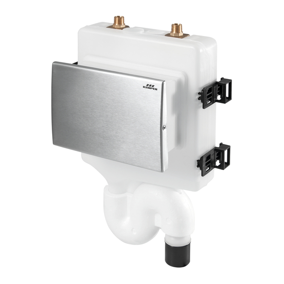
KEMPER KHS HS2 Hygienespülung
(Firmware-Version: 772)
Data Sheet External Contol
KEMPER KHS HS2 Hygiene Flushing Box
(firmware version: 772)
Fiche Technique Contrôle Externe
KEMPER KHS HS2 Rinçage d'Hygiène
(firmware version: 772)
Datablad Externe Sturing
KEMPER KHS HS2 Hygiënespoeler
(firmware versie: 772)
K410068905002-00 10.2017
1
EN
DE
FR
NL
DE
Kapitel
Inhaltsverzeichnis

Verwandte Anleitungen für Kemper KHS HS2


Inhaltszusammenfassung für Kemper KHS HS2
- Seite 1 Datenblatt Externe Ansteuerung KEMPER KHS HS2 Hygienespülung (Firmware-Version: 772) Data Sheet External Contol KEMPER KHS HS2 Hygiene Flushing Box (firmware version: 772) Fiche Technique Contrôle Externe KEMPER KHS HS2 Rinçage d’Hygiène (firmware version: 772) Datablad Externe Sturing KEMPER KHS HS2 Hygiënespoeler (firmware versie: 772) K410068905002-00 10.2017...
-
Seite 2: Inhaltsverzeichnis
Dieses Dokument enthält die technischen Spezifikationen für die Gebäudeleittechnik- Schnittstellen der Produkte: • Fig. 689 03 001 KEMPER KHS HS2 Hygienespülung mit einem Anschluss • Fig. 689 03 002 KEMPER KHS HS2 Hygienespülung mit zwei Anschlüssen • Fig. 689 03 003 KEMPER KHS HS2 Hygienespülung mit Durchflusssensor, mit einem Anschluss •... -
Seite 3: Übersicht Gebäudeleittechnik-Schnittstellen
Ausgabe des Spül- und Ereignissprotkolls (CSV- • Datei) • Datalogging Tabelle 1: Funktion der Gebäudeleittechnik-Schnittstellen Anschlüsse Die externen Steuerungen werden wie folgt an die Steuereinheit der KEMPER KHS HS2 Hygienespülung angeschlossen: Schnittstelle Anschluss Stecker Anschlusskabel Digital I/O fünfpolig Kabel für Schnittstelle Digital I/O, Fig. 689 05 001... -
Seite 4: Schnittstelle Digital I/O
Grundeinstellungen sind ausschließlich mit der KEMPER HS2-App zu setzen. Umschaltung auf Slave-Betrieb Bei der Anbindung der KEMPER KHS HS2 Hygienespülung an eine Gebäudeleittechnik wird die Steuereinheit wie folgt in den Slave-Modus versetzt: • Schnittstelle Digital I/O: durch Empfangen des Bereitschaftssignals am Eingang Klemme 5-, siehe Seite 7 K410068905002-00 10.2017... -
Seite 5: Anschlussschema
Abbildung 2: Anschlussschema Schnittstelle Digital I/O A Kabel für Schnittstelle Digital I/O, Fig. 689 05 001 B Steuereinheit der KEMPER KHS HS2 Hygienespülung Eingang für Spülauslösung (Klemme 5) Arbeitskontakt für Signal „Spülung aktiv“ (Klemme 4) Arbeitskontakt für Signal „Status OK“ (Klemme 3) -
Seite 6: Anschlussspezifikation
Anschlussspezifikation Pos. Farbe Signal Funktion Eigenschaften Gemeinsamer Kontakt grün OUT COMMON – – der Ausgänge Potentialfreier Arbeitskontakt, weiss OUT STATUS OK Signal „Störung“ Ausgang Kontaktbelastung: ≤ 24V AC/DC, ≤ 0,5A Potentialfreier Arbeitskontakt, braun OUT FLUSH ACT Signal „Spülung aktiv“ Ausgang Kontaktbelastung: ≤... -
Seite 7: Bereitschaft
2 Magnetventil V2 3 Magnetventile V1 und V2 4 Bereitschaftssignal (keine Spülauslösung) Bereitschaft Die Gebäudeleittechnik muss der KEMPER KHS HS2 Hygienespülung periodisch die Bereitschaft melden. Dazu dient das Bereitschaftssignal, siehe Abbildung 4. Für das Bereitschaftssignal gelten die folgenden Bedingungen: Versetzt die KEMPER KHS HS2 Hygienespülung in den Slave-Modus Nach dem Einschalten muss ein Bereitschaftssignal folgen. -
Seite 8: Status
KEMPER KHS HS2 Hygienespülung nicht in eine Gebäudeleittechnik integriert ist. Rückwärtskompatibilität Falls bei einer KEMPER KHS Hygienespülung (Baujahr bis 2014) die Steuereinheit gegen eine Steuereinheit der KEMPER KHS Hygienespülung (Baujahr ab 2014) ersetzt wird, sind die folgenden Informationen zur Rückwärtskompatibilität zu beachten. -
Seite 9: Schnittstelle Can-Bus
4 Schnittstelle CAN-Bus Hinweise 4.1.1 Ansteuerung Die Ansteuerung der KHS HS2 Hygienespülung über CAN-Bus wird in der Einbau- und Bedienungsanleitung der KHS Mini Systemsteuerung -MASTER 2.0- beschrieben. 4.1.2 Elektrischer Anschluss Der Anschluss der KHS HS2 Hygienespülung über CAN-Bus wird in der Einbau- und Bedienungsanleitung des KHS Verbindungssets HS2 an KHS Mini Systemsteuerung (Fig. - Seite 21 Datenblatt Externe Ansteuerung KEMPER KHS HS2 Hygienespülung (Firmware-Version: 772) Data Sheet External Contol KEMPER KHS HS2 Hygiene Flushing Box (firmware version: 772) Fiche Technique Contrôle Externe KEMPER KHS HS2 Rinçage d’Hygiène (firmware version: 772) Datablad Externe Sturing KEMPER KHS HS2 Hygiënespoeler (firmware versie: 772) K410068905002-00 10.2017...
- Seite 31 Datenblatt Externe Ansteuerung KEMPER KHS HS2 Hygienespülung (Firmware-Version: 772) Data Sheet External Contol KEMPER KHS HS2 Hygiene Flushing Box (firmware version: 772) Fiche Technique Contrôle Externe KEMPER KHS HS2 Rinçage d’Hygiène (firmware version: 772) Datablad Externe Sturing KEMPER KHS HS2 Hygiënespoeler (firmware versie: 772) K410068905002-00 10.2017...