Danfoss Prof 1 CIP Installationsanleitung
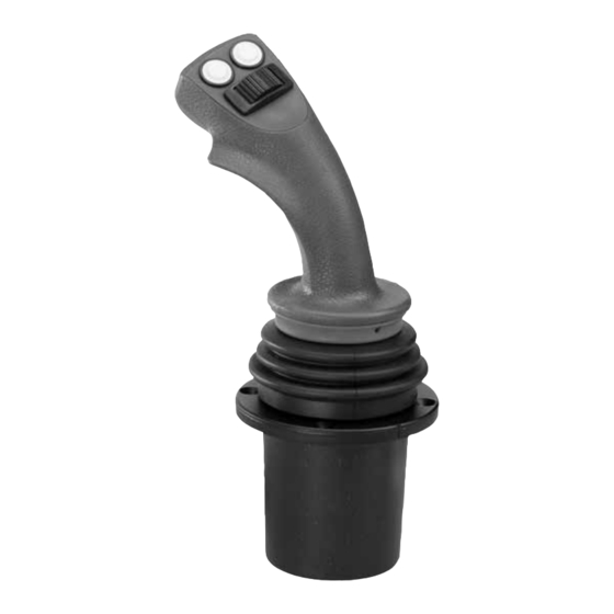
Joystick
Quicklinks
Installation Guide
Joystick Prof 1
CIP
Montering
Mounting
Montage
Montage
© Danfoss, 2014-03
L1317817 • Rev AB • Mar 2014
Positionering af greb
Positioning of grip
Positionierung des griffes
Positionnement de la poignée
Nøglevidde
Moment
Across flats
torque
H
Schlüsselweite
Anzungsmoment
Surplats
Couple de serrage
2.5
2.1 Nm
1

Verwandte Anleitungen für Danfoss Prof 1 CIP


Inhaltszusammenfassung für Danfoss Prof 1 CIP
- Seite 1 Montering Positionering af greb Mounting Positioning of grip Montage Positionierung des griffes Montage Positionnement de la poignée Nøglevidde Moment Across flats torque Schlüsselweite Anzungsmoment Surplats Couple de serrage 2.1 Nm © Danfoss, 2014-03 L1317817 • Rev AB • Mar 2014...
- Seite 2 It is important to ensure termination at both ends of the CAN-bus. The termination contains a 120 Ω resistance and is contained in Prof 1 CIP. To keep it simple, pin 16 CAN- is connected to a 120 Ω resistance. If Prof 1 CIP is the last CAN component on the bus the termination can be ensured by incorporating a shunt between CAN+ (pin 4) and CAN-Term (pin 1).
- Seite 3 Le manipulateur fonctionne en mode maître CAN Open Closed Débit de communication et ID noeuds définis par logiciel Open Débit de communication et numéro d’identité standard Closed Open Closed Open © Danfoss, 2014-03 L1317817 • Rev AB • Mar 2014...
- Seite 4 Max supply voltage 36 V DC Max ripple Note: Contrary to analogue joysticks (such as Prof 1) PROF 1 CIP can be connected direct to the battery and does not need supply voltage directly from the PVE’s. Technische Daten Stromversorgung...