
Verwandte Anleitungen für Dräger REGARD 2410


Inhaltszusammenfassung für Dräger REGARD 2410
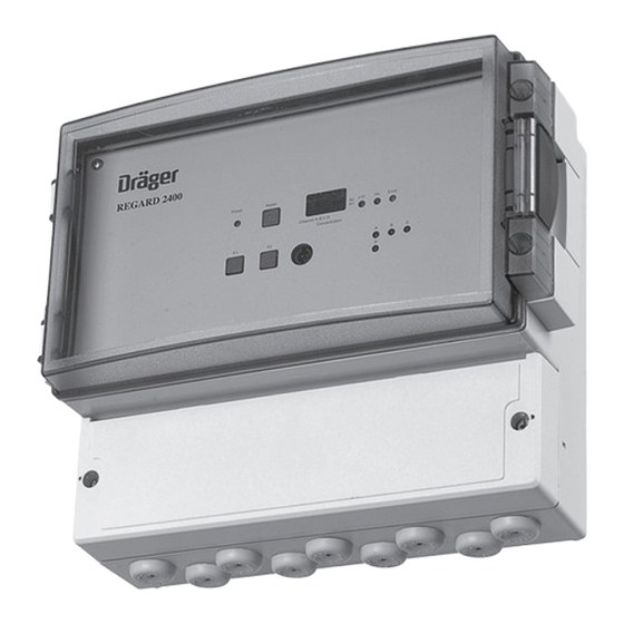
- Seite 1 ® Dräger REGARD 2400 / 2410 4-Kanal Gaswarnzentrale Gebrauchsanweisung, Seite 2 bis 27 Four Channel Control Unit Instructions for Use, Page 28 to 53...
-
Seite 2: Inhaltsverzeichnis
Dräger REGARD 2400 / 2410 in Verbindung mit katalytischen Sensoren ..11 Zubehör ............................ 11 8.1. Installation des internen Habbrückenkonverters ..............11 8.2. Polytron EC Transmitter mit einem Dräger REGARD 2410 über eine Sicherheitsbarriere........................12 8.3. Digitale Eingänge ........................13 8.4. -
Seite 3: Zu Ihrer Sicherheit
Zu Ihrer Sicherheit Zu Ihrer Sicherheit Gebrauchsanweisung beachten Jede Handhabung an der Gaswarnzentrale setzt die genaue Kenntnis und Beachtung dieser Gebrauchsanweisung voraus. Die Gaswarnzentrale ist nur für die beschriebene Verwendung bestimmt. Instandhaltung Die Gaswarnzentrale muss regelmäßigen Inspektionen und Wartungen durch Fachleute unterzogen werden. -
Seite 4: Verwendungszweck
Verwendungszweck Produktbeschreibung Produktmerkmale Verwendungszweck Der Zweck des Dräger REGARD 2400 / 2410 ist es, brennbare, toxische und/oder andere Gase zu überwachen sowie Alarmsignale, Anzeigevorrichtungen und andere Geräte über Alarmrelais zu steuern. GEFAHR Dräger REGARD 2400 / 2410 ist nicht dafür bestimmt oder zugelassen, in Bereichen zu arbeiten, wo es zu einer möglichen Entwicklung von zündfähigen oder explosiblen Gasgemi- schen kommen kann. -
Seite 5: Bedien- Und Anzeigeelemente
Bedien- und Anzeigeelemente Power Reset Horn Error Channel A B C D Concentration REGARD 2410 Inhibit Mode setzen (siehe “Das Menü” auf Seite 18) Aktuellen Kanal halten; Messbereiche/Alarmschwellen ansehen (siehe “Konfigurations- Informations-Menü” auf Seite 20) Reset Reset Hupe und Alarm, Inhibit Mode verlassen LED Power (grün) -
Seite 6: Elektrische Anschlüsse Installieren
Die Zuleitung zum Gaswarngerät sollte separat abgesichert sein (maximal 1 A). Anschlussbild Dräger REGARD 2410 Die Abbildung zeigt ein Dräger REGARD 2410. Die Spannungsversorgung des Gerätes beträgt 24 VDC. Die Abbildung zeigt das Gerät im spannungslosen Zustand. Wird das Gerät eingeschaltet sind das Error- und die Alarmrelais angezogen und geöffnet (energized, normally open). - Seite 7 Elektrische Anschlüsse installieren Die Tabelle zeigt die Klemmenbelegung beim Dräger REGARD 2400 / 2410. Anschlussklemme Klemmenbezeichnung +24 V 24 VDC Input RS485 Interface Fault norm. closed / Öffner Alarm 1 norm. closed / Öffner Alarm 2 norm. closed / Öffner Hupe norm.
- Seite 8 Elektrische Anschlüsse installieren Anschlussbelegung Dräger REGARD 2400 Die Darstellung zeigt ein Dräger REGARD 2400. Die Spannungsversorgung beträgt 230 VAC oder 24 VDC. Error Alarm 2 Alarm 1 Horn Channel Channel 19 20 21 22 23 24 Channel Channel 7 8 9 10 11 12 13 14 15 16 17 18 1 2 3...
- Seite 9 Elektrische Anschlüsse installieren Anschlussbild Dräger REGARD 2400 Hauptplatine REGARD 2400 Hauptplatine INTERNES NETZTEIL 110/230 V AC 24 V DC Input Output 24 V DC Input +24 V Error Alarm 2 Alarm 1 Horn Channel Channel 19 20 21 22 23 24 Channel Channel 7 8 9...
- Seite 10 Elektrische Anschlüsse installieren Die Tabelle zeigt die Klemmenbelegung beim Dräger REGARD 2400. Anschlussklemme Klemmenbezeichnung mit SE Ex 4...20 mA Konvertermodul Kanal A +24 V braun Signal gelb schwarz Kanal B +24 V braun Signal gelb schwarz Fault Wechsler Alarm 2 Wechsler Alarm 1 Wechsler...
-
Seite 11: Dräger Regard 2400 / 2410 In Verbindung Mit Katalytischen Sensoren
Dräger REGARD 2400 / 2410 in Verbindung mit katalytischen Sensoren* WICHTIGER HINWEIS ! Wenn ein Dräger REGARD 2400 oder Dräger REGARD 2410 mit einem katalytischen Sen- sor verbunden wird, muss ein Halbbrückenkonverter verwendet werden! Es gibt 2 verschie- dene Konverter, die verwendet werden können: SC00016 interner Konverter für Dräger REGARD 2400... -
Seite 12: Polytron Ec Transmitter Mit Einem Dräger Regard 2410 Über Eine Sicherheitsbarriere
Zubehör 8.2. Polytron EC* Transmitter mit einem Dräger REGARD 2410 über eine Sicherheitsbarriere Anschlussbeispiel: Ex-Bereich Nicht-Ex-Bereich 230 VAC 24 VDC Polytron – Dräger REGARD 24xx 4...20 mA Input 4...20mA Sicherheitsbarriere z. B. Stahl 9160/13-11-11 Bei Verwendung von Sicherheitsbarrieren anderer Hersteller, ist es notwendig die Installati- ons- und Gebrauchsanweisung der Sicherheitsbarriere zu beachten. -
Seite 13: Digitale Eingänge
Es ist z.B. möglich einen dieser Eingänge für einen externen Hupenreset zu nutzen. 8.4. RS485 Ausgangskontakt am Dräger REGARD 2400 / 2410 Es gibt am Dräger REGARD 2400 und Dräger REGARD 2410 drei Kontakte für die Kommuni- kation mit optionalen Modulen (für Dräger REGARD 2400 siehe Anschlussbelegung Seite 6, für Dräger REGARD 2410 siehe Anschlussbelegung Seite 8). -
Seite 14: Das I/O Modul
Das I/O Modul Das I/O Modul A B Com A B Com S1 0V S2 0V S3 0V S4 0V S5 0V S6 0V RS 485 Analoge Ausgänge 4...20 mA Power Digitale Eingänge +24 V + D3 + D4 + D5 + D6 + D7 + D8... -
Seite 15: Das Relaismodul
Das Relaismodul 10. Das Relaismodul A B Com A B Com PWR RX TX Adr RS485 Relay 7 Relay 8 Relay 9 Relay 10 Relay 11 Relay 12 Relay module Relay 1 Relay 2 Relay 3 Relay 4 Relay 5 Relay 6 Power +24V... - Seite 16 Das Relaismodul Modul Adressen Schalter am Relaismodul Adresse Konfiguration für 1 Relaismodul Konfiguration für 2 Relaismodule Konfiguration für 3 Relaismodule Konfiguration für 4 Relaismodule WICHTIGER HINWEIS ! Wenn ein I/O Modul installiert worden ist, muss die Adressierung auf dem Relaismodul 1 bis 3 (in der Software 4 bis 6) sein.
-
Seite 17: Das Dräger Regard 2400 / 2410 Gerätemenü
Das Dräger REGARD 2400 / 2410 Gerätemenü 11. Das Dräger REGARD 2400 / 2410 Gerätemenü Das Dräger REGARD 2400 / 2410 hat ein internes Gerätemenü um die Konfiguration und Einstellungen auszulesen. Über das Menü kann das Gerät in den Inhibit Mode gesetzt werden und die Mittelwertsbildung überbrückt werden (beides zeitlich begrenzt auf 20 Minuten). - Seite 18 Das Dräger REGARD 2400 / 2410 Gerätemenü Das Menü Rollierende Messanzeige F1+F2 Fehler INHI Inhibit - Funktion Codeeingabe Aktive F1+F2 Inhibit - Funktion Fehler F1+F2 MOFF Mittelwert Codeeingabe überbrückt F1+F2 Mittelwert überbrücken Fehler F1+F2 TOUT Untermenü Codeeingabe Relaistest F1+F2 Relais testen F1+F2 SOFT V2.1...
- Seite 19 Das Dräger REGARD 2400 / 2410 Gerätemenü Das Relais-Test-Menü F1+F2 ist der aktuelle Relaiszustand spannungslos mit Spannung T1 x Alarmrelais 1 F1+F2 T2 x Alarmrelais 2 F1+F2 THUx Hupenrelais F1+F2 TERx Störungsrelais F1+F2...
- Seite 20 Das Dräger REGARD 2400 / 2410 Gerätemenü Konfigurations-Informations-Menü R1 x A1Fu A2Fu A123 Funktion des * Alarmfunktion * Alarmfunktion Messwert Relais 1 Grenzwert 1 Grenzwert 2 F1 o. F2 A Un R1xx A1Le A2Le Messeinheit Zeitfunktion des * Level des * Level des des Kanals Relais 1...
-
Seite 21: Die Konfiguration
Die Konfiguration Wartung 12. Die Konfiguration Die komplette Konfiguration des Dräger REGARD 2400 / 2410 erfolgt über eine Konfigurati- onssoftware die mittels Laptop/PC auf das Dräger REGARD 2400 / 2410 geladen wird. Für eine detaillierte Anleitung zur Konfiguration lesen Sie bitte die Software-Konfigurations Anleitung. - Seite 22 Wartung Versorgungsstrom Spannung Mess- Versorgungsstrom Spannung Mess- der Halbbrücke in punkt Halbbrücken- der Halbbrücke in punkt Halbbrücken- Strom in V Strom in V 1,248 1,373 1,253 1,378 1,258 1,383 1,263 1,388 1,268 1,393 1,273 1,398 1,278 1,403 1,283 1,408 1,288 1.413 1,293 1,418...
-
Seite 23: Potentiometer Und Testpunkte Am Internen Halbbrückenkonverter
Wartung Referenzpunkt (Empfindlichkeit) abgleichen Der Sensor ist mit einem Referenzgas (z.B.: 50 %UEG) zu beaufschlagen. Am "Messpunkt 4...20 mA" kann der Ausgangsstrom unter Verwendung eines Voltmeters kontrolliert werden. Die Verwendung der Anzeige des Dräger REGARD 2400 selbst ist auch möglich. Mit Hilfe des Potentiometers "Abgleichpoti Messbereich des Sensors"... -
Seite 24: Technische Daten
Technische Daten 14. Technische Daten Dräger REGARD 2410 Versorgungsspannung 24 VDC ±10 % Nennleistung ohne angeschlossene ca. 2,5 W Sensoren 4...20 mA Eingangskanäle Digitale Eingänge 4...20 mA, Eingangsbürde 350 Ω Eingang Störung bei <3,5 mA Störung bei >23 mA Hysterese für Störung 0,2 mA... - Seite 25 Technische Daten Dräger REGARD 2400 Versorgungsspannung AC 110/230 VAC ±10 %, 50hz Versorgungsspannung DC 24 VDC ±10% Nennleistung ohne angeschlossene ca. 3 W Sensoren 4...20 mA Eingangskanäle Digitale Eingänge 4...20 mA, Eingangsbürde 350 Ω Eingang Störung bei <3,5 mA Störung bei >23 mA Hysterese für Störung 0,2 mA Ausgaberelais Alarm1 und 2...
- Seite 26 Technische Daten I/O Modul Versorgungsspannung DC 24 VDC ±10 % Nennleistung ca. 3 W Kommunikation RS485 Input 6 digital Eingänge Output 6 analog Ausgänge Umgebungs-Bedingungen Temperatur: –20 C bis 60 Feuchte: 10 % bis 90 % r.F. Kabelanschluss Schraubklemmen eindrahtig bis 4 mm feindrähtig bis 2,5 mm Maße (H x B x T) 90 mm x 105 mm x 72 mm...
-
Seite 27: Bestellliste
Dräger REGARD 2400 Externes Konvertermodul SE Ex 4...20 mA 36 04 655 für Hutschienenmontage, für Dräger REGARD 2410 I/O Modul für Dräger REGARD 2400 / 2410 SC 00 018 Relaismodul für Dräger REGARD 2400 / 2410 SC 00 019 Konfigurationsset International (Kabel und Software) - Seite 28 Dräger REGARD 2400 / 2410 and Catalytic Bead Sensors ........37 Accessories ..........................37 8.1. Installation of a Semi-Bridge Converters................37 8.2. Polytron EC Transmitter to Dräger REGARD 2410 via a Safety Barrier ...... 38 8.3. Digital Inputs..........................39 8.4. RS485 Output Terminal Dräger REGARD 2400 / 2410 ..........39 8.5.
-
Seite 29: For Your Safety
For Your Safety For Your Safety Strictly follow the Instructions for Use Any use of the control unit requires full understanding and strict observation of these Instruc- tions for Use. The control unit is only to be used for purposes specified here. Maintenance The control unit must be inspected and serviced regularly by trained service personnel. -
Seite 30: Intended Use
Intended Use Product Description Product Features Intended Use The Dräger REGARD 2400 / 2410 is used to monitor combustible, toxic, and/or other gases and to control alarm signals, display units and other devices via alarm relays. DANGER Dräger REGARD 2400 / 2410 must not be used and is not approved for use in areas where flammable and explosive gas mixtures may occur. -
Seite 31: Indicating And Control Elements
Indicating and Control Elements Power Reset Horn Error Channel A B C D Concentration REGARD 2410 Set Inhibit Mode (see “Menu” on page 44) Hold current channel; Watch configuration (see “Configuration-Information-Menu” on page 46) Reset Reset horn and alarm, leave Inhibit mode... -
Seite 32: Electrical Connections And Installation
. The supply voltage for the control unit must be equipped with a separate fuse (maximum 1 A). Connection Diagram Dräger REGARD 2410 The picture shows a Dräger REGARD 2410. The supply voltage is 24 VDC. The picture shows the unit in an unpowered condition. - Seite 33 Electrical Connections and Installation The table shows the connection on the terminals of the Dräger REGARD 2410 / 2410. Terminal Description +24 V 24 VDC Input RS485 Interface Fault norm. closed Alarm 1 norm. closed Alarm 2 norm. closed Horn norm.
- Seite 34 Electrical Connections and Installation Connection Diagram Dräger REGARD 2400 The picture shows a Dräger REGARD 2400. The mains supply voltage is 230 VAC or 24 VDC. Error Alarm 2 Alarm 1 Horn Channel Channel 19 20 21 22 23 24 Channel Channel 7 8 9...
- Seite 35 Electrical Connections and Installation Connection diagram Dräger REGARD 2400 Mainboard INTERNAL POWER SUPPLY UNIT REGARD 2400 Mainboard 110/230 V AC 24 V DC Input Output 24 V DC Input +24 V Error Alarm 2 Alarm 1 Horn Channel Channel 19 20 21 22 23 24 Channel Channel...
- Seite 36 Electrical Connections and Installation The table shows the connection on the terminals of the Dräger REGARD 2400. Terminal Description with SE Ex 4...20 mA Converter Module Channel A +24 V brown signal yellow black Channel B +24 V brown signal yellow black Fault...
-
Seite 37: Dräger Regard 2400 / 2410 And Catalytic Bead Sensors
Dräger REGARD 2400 / 2410 and Catalytic Bead Sensors* IMPORTANT NOTICE: If a Dräger REGARD 2400 or Dräger REGARD 2410 should be connected to a catalytic bead sensor a semi bridge converter has to be used! There are 2 different converters that could be used: SC00016 internal converter for Dräger REGARD 2400... -
Seite 38: Polytron Ec Transmitter To Dräger Regard 2410 Via A Safety Barrier
Accessories 8.2. Polytron EC* Transmitter to Dräger REGARD 2410 via a Safety Barrier Example for Connection: Ex Area Safe Area 230 VAC 24 VDC Polytron – Dräger REGARD 24xx 4...20 mA Input 4...20mA Safety Barrier e.g. Stahl 9160/13-11-11 When using Safety Barriers from other suppliers, it is recommended that you refer to the Installation and Operating manual of the specific Safety Barrier being used. -
Seite 39: Digital Inputs
8.4. RS485 Output Terminal Dräger REGARD 2400 / 2410 On the Dräger REGARD 2400 and Dräger REGARD 2410 there are 3 contacts for the com- munication with optional modules (for Dräger REGARD 2400 see connection diagram page 32, for Dräger REGARD 2410 see connection diagram page 34) like I/O module (see... -
Seite 40: I/O Module
+ D8 The I/O module (input-output module) has 6 digital inputs and 6 analog outputs. The module communicates with the Dräger REGARD 2400 / Dräger Regard 2410 via the RS485 connec- tion. To connect the module with the Dräger REGARD 24xx the terminals A / B / COM must be used. -
Seite 41: Relay Module
Relay Module 10. Relay Module A B Com A B Com PWR RX TX Adr RS485 Relay 7 Relay 8 Relay 9 Relay 10 Relay 11 Relay 12 Relay module Relay 1 Relay 2 Relay 3 Relay 4 Relay 5 Relay 6 Power +24V... - Seite 42 Relay Module Module address Switch on Relay module address This represents module one This represents module two This represents module three This represents module four IMPORTANT NOTICE: When an I/O module is installed the addressing of the relay modules must be 1 to 3 only. The configuration address in the configuration software and the relay modules must be the same.
-
Seite 43: The Dräger Regard 2400 / 2410 Menu
The Dräger REGARD 2400 / 2410 Menu 11. The Dräger REGARD 2400 / 2410 Menu The Control Unit Dräger REGARD 2400 / 2410 has a menu to check instrument data or relays output. It's also possible to set the controller to an inhibit mode or to set the average values off (both temporary for 20 minutes). - Seite 44 The Dräger REGARD 2400 / 2410 Menu Menu Value F1+F2 Error INHI Inhibit Function Code Activated F1+F2 Inhibit Function Error F1+F2 MOFF Average Value Code F1+F2 Average Value OFF Error F1+F2 TOUT Sub Menu Code Relay Test F1+F2 Relay Test F1+F2 SOFT V2.1...
- Seite 45 The Dräger REGARD 2400 / 2410 Menu Relay-Test-Menu F1+F2 current conditon de-energized energized T1 x Alarm relay 1 F1+F2 T2 x Alarm relay 2 F1+F2 THUx Horn relay F1+F2 TERx Error relay F1+F2...
- Seite 46 The Dräger REGARD 2400 / 2410 Menu Configuration-Information-Menu A1Fu A2Fu R1 x A123 * Alarm function * Alarm function Function relay 1 Value threshold 1 threshold 2 F1 o. F2 A1Le A2Le R1xx A Un * value * value Time function Unit threshold 1 threshold 2...
-
Seite 47: Configuration
Configuration Maintenance 12. Configuration The configuration of the Dräger REGARD 2400 / 2410 is done by configuration software. For configuration details please refer to the Configuration Instructions CAUTION After any work with the configurration software the programming of the unit must be tested at the control unit! 13. - Seite 48 Maintenance Converter Supply Voltage at Testport Converter Supply Voltage at Testport Current for Converter Current for Converter in mA Current in V in mA Current in V 1.248 1.373 1.253 1.378 1.258 1.383 1.263 1.388 1.268 1.393 1.273 1.398 1.278 1.403 1.283 1.408...
-
Seite 49: Potentiometers And Test Points At The Converter
Maintenance Adjusting the span Apply span gas (e.g. 50 %LEL) to the sensor. The output current can be checked with a voltmeter at the two test points on the left hand side of the converter "Measuring Point 4...20mA". Alternatively you may refer to the display of the Dräger REGARD 2400, provided that the corresponding channel is configured cor- rectly. -
Seite 50: Technical Data
Technical Data 14. Technical Data Dräger REGARD 2410 Supply Voltage d.c. 24 VDC ±10 % Power Consumption w/o connected Approx. 2.5 W sensors 4...20 mA Input Channels Digital Inputs Input 4...20 mA, input load 350 Ohm error at <3.5 mA error at >23 mA... - Seite 51 Technical Data Dräger REGARD 2400 Supply Voltage a.c. 110/230 VAC ±10 %, 50hz Supply Voltage d.c. 24 VDC ±10 % Power Consumption w/o connected Approx. 3 W sensors 4...20 mA Input Channels Digital Inputs Input 4...20 mA, input load 350 Ohm error at <3.5 mA error at >23 mA fault hysteresis 0.2 mA...
- Seite 52 Technical Data I/O Module Supply Voltage d.c. 24 VDC ±10 % Power Consumption Approx. 3 W Communication RS485 Input 6 digital inputs Output 6 analogue outputs Ambient Conditions Temperature: –20 C to 60 Relative Humidity: 10 % to 90 % r.h. Cable Terminals Screw terminals for solid wires up to 4 mm...
-
Seite 53: Order List
Dräger REGARD 2400 External Converter Module SE Ex 4-20 mA, 36 04 655 DIN Rail mounting, for Dräger REGARD 2410 I/O module for Dräger REGARD 2400 / 2410 SC 00 018 Relay module for Dräger REGARD 2400 / 2410 SC 00 019 Configuration Set International (Cable and Software) -
Seite 54: Zulassungen / Appovals
Zulassungen / Appovals Zulassungen / Appovals... - Seite 55 Zulassungen / Appovals...
- Seite 56 Zulassungen / Appovals...
-
Seite 57: Konformitätserklärung / Decaration Of Conformity
Zulassungen / Appovals... -
Seite 58: Konformitätserklärung / Decaration Of Conformity
Konformitätserklärung / Decaration of Conformity Konformitätserklärung / Decaration of Conformity... - Seite 60 Dräger Safety AG & Co. KGaA Revalstraße 1 D-23560 Lübeck Germany Tel. +49 451 8 82- 0 +49 451 8 82- 20 80 www.draeger.com 90 33 025 - GA 4675.896 de_en © Dräger Safety AG & Co. KGaA 1st edition - 07_2007...