Stahl Ex i Betriebsanleitung

Verwandte Anleitungen für Stahl Ex i


Inhaltszusammenfassung für Stahl Ex i
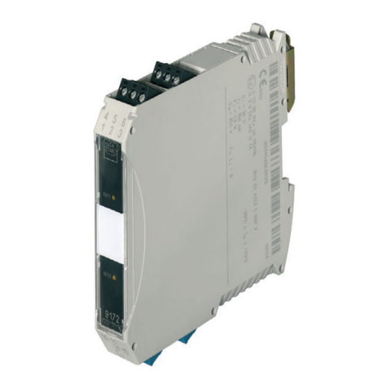
- Seite 1 Betriebsanleitung Additional languages r-stahl.com Ex i Relais Modul Reihe 9172...
-
Seite 2: Inhaltsverzeichnis
Inbetriebnahme ....................14 Betrieb .......................14 10.1 Betrieb .......................14 10.2 Anzeigen ......................14 10.3 Fehlerbeseitigung .....................14 Instandhaltung, Wartung, Reparatur ..............15 11.1 Instandhaltung ....................15 11.2 Wartung ......................15 11.3 Reparatur ......................15 11.4 Rücksendung ....................16 Entsorgung ......................16 Zubehör und Ersatzteile ...................16 Ex i Relais Modul Reihe 9172... -
Seite 3: Allgemeine Angaben
Diese ist rechtsverbindlich in allen juristischen Angelegenheiten. Weitere Dokumente • Installationsanleitung Schaltschrank • Datenblatt • FMEDA Report SIL Dokumente in weiteren Sprachen, siehe r-stahl.com. Konformität zu Normen und Bestimmungen Zertifikate und EU-Konformitätserklärung, siehe r-stahl.com. Das Gerät verfügt über eine IECEx-Zulassung. Zertifikat siehe IECEx-Homepage: http://iecex.iec.ch/ Weitere nationale Zertifikate stehen unter dem folgenden Link zum Download bereit: https://r-stahl.com/de/global/support/downloads/. -
Seite 4: Erläuterung Der Symbole
Gefahren für Personen Nichtbeachtung der Anweisung kann zu leichten Verletzungen bei Personen führen. HINWEIS Vermeidung von Sachschaden Nichtbeachtung der Anweisung kann zu einem Sachschaden am Gerät und/oder seiner Umgebung führen. Ex i Relais Modul 160372 / 9172601310 Reihe 9172 2019-02-11·BA00·III·de·07... -
Seite 5: Symbole Am Gerät
Normen und Bestimmungen umfasst. Für Tätigkeiten in explosionsgefährdeten Bereichen sind weitere Kenntnisse erforderlich! R. STAHL empfiehlt einen Kenntnisstand, der in folgenden Normen beschrieben wird: • IEC/EN 60079-14 (Projektierung, Auswahl und Errichtung elektrischer Anlagen) • IEC/EN 60079-17 (Prüfung und Instandhaltung elektrischer Anlagen) •... -
Seite 6: Sichere Verwendung
Stromkreis können sich andere sicherheitstechnische Werte ergeben. Hierbei kann die Eigensicherheit gefährdet werden! • Stromkreise der Zündschutzart "Ex i", die mit Stromkreisen anderer Zündschutzarten betrieben wurden, dürfen danach nicht mehr als Stromkreise der Zündschutzart "Ex i" betrieben werden. Inbetriebnahme, Wartung, Reparatur •... -
Seite 7: Umbauten Und Änderungen
• Gerät nur entsprechend dem in dieser Betriebsanleitung genannten Einsatzzweck verwenden. Funktion Einsatzbereich Das Ex i Relais Modul trennt voneinander eigensichere und nicht eigensichere Stromkreise bzw. verschiedene eigensichere Stromkreise. Arbeitsweise Je nach Ausführung wird entweder die Ansteuerung oder der Kontaktausgang bzw. -
Seite 8: Technische Daten
Spannung U 30 V AC 45 V DC 30 V DC 0,5 A max. Strom I Innere Kapazität C vernachlässigbar Innere Induktivität L vernachlässigbar Sicherheits- 253 V AC technische Maximalspannung Ex i Relais Modul 160372 / 9172601310 Reihe 9172 2019-02-11·BA00·III·de·07... - Seite 9 -20 ... +70 °C Gruppenmontage -20 ... +70 °C Einbaubedingungen beeinflussen die Umgebungstemperatur. "Installationsanleitung Schaltschrank" beachten Lagertemperatur -40 ... +80 °C Relative Feuchte 95 % (keine Betauung) Verwendung in Höhe < 2000 m 160372 / 9172601310 Ex i Relais Modul 2019-02-11·BA00·III·de·07 Reihe 9172...
-
Seite 10: Projektierung
– - flexibel mit Aderendhülsen 0,25 ... 1 mm 0,5 ... 1 mm Anschlussplan Siehe Geräteaufdruck Weitere technische Daten, siehe r-stahl.com. Projektierung HINWEIS Ausfall der installierten Geräte im Schaltschrank durch zu hohe Umgebungstemperatur! Nichtbeachten kann zu Sachschäden führen. • Schaltschrank so aufbauen und einrichten, dass er immer innerhalb des zulässigen Temperaturbereichs betrieben wird. -
Seite 11: Transport Und Lagerung
Explosionsschutz aufgrund äußerer Einflüsse nicht beeinträchtigt wird, z.B. Druckbedingungen, chemische, mechanische, thermische, elektrische Einflüsse sowie Schwingungen, Feuchte, Korrosion (siehe IEC/EN 60079-14). • Gerät nur durch geschultes und mit den einschlägigen Normen vertrautes Fachpersonal installieren lassen. 160372 / 9172601310 Ex i Relais Modul 2019-02-11·BA00·III·de·07 Reihe 9172... -
Seite 12: Maßangaben / Befestigungsmaße
06886E00 Demontage • Fußriegel mit dem Schraubendreher etwas herausziehen. • Gerät herausschwenken. 06881E00 8.2.2 Montage / Demontage auf pac-Träger Siehe Betriebsanleitung pac-Träger Typ 9195. Ex i Relais Modul 160372 / 9172601310 Reihe 9172 2019-02-11·BA00·III·de·07... -
Seite 13: Installation
Geräteausfall durch elektrostatisch überladene Bauelemente! Nichtbeachten kann Sachschaden verursachen! • Vor Arbeiten am Gerät körpereigene Spannung an geerdeten Metallteilen entladen oder ein ESD-Ableitband anlegen. 8.3.2 Prinzipschaltbilder Siehe Geräteaufdruck oder Technische Daten. 160372 / 9172601310 Ex i Relais Modul 2019-02-11·BA00·III·de·07 Reihe 9172... -
Seite 14: Inbetriebnahme
Betrieb 10.1 Betrieb Grundfunktion: Binär-Eingang / Ausgang, 1 und 2 Kanäle. Das Ex i Relais Modul wird zum Trennen von eigensicheren und nicht eigensicheren Signal- und Steuerstromkreisen eingesetzt. Je nach Ausführung erfolgt die Ansteuerung oder das Steuersignal mit eigensicheren Stromkreisen. -
Seite 15: Instandhaltung, Wartung, Reparatur
Die geltenden nationalen Bestimmungen im Einsatzland beachten. 11.3 Reparatur GEFAHR Explosionsgefahr durch unsachgemäße Reparatur! Nichtbeachten führt zu schweren oder tödlichen Verletzungen. • Reparaturen an den Geräten ausschließlich durch R. STAHL Schaltgeräte GmbH ausführen lassen. 160372 / 9172601310 Ex i Relais Modul 2019-02-11·BA00·III·de·07 Reihe 9172... -
Seite 16: Rücksendung
Entsorgung 11.4 Rücksendung • Rücksendung bzw. Verpackung der Geräte nur in Absprache mit R. STAHL durchführen! Dazu mit der zuständigen Vertretung von R. STAHL Kontakt aufnehmen. Für die Rücksendung im Reparatur- bzw. Servicefall steht der Kundenservice von R. STAHL zur Verfügung.