Stahl 24 V Betriebsanleitung

Verwandte Anleitungen für Stahl 24 V


Inhaltszusammenfassung für Stahl 24 V
- Seite 1 Betriebsanleitung Operating instructions Additional languages www.stahl-ex.com DE EN Digital Input Output Modul 24 V für Zone 2 Ex n Digital Input Output Module 24 V for Ex n Zone 2 Reihe 9472/35 Series 9472/35...
- Seite 3 Betriebsanleitung Additional languages www.stahl-ex.com Digital Input Output Modul 24 V für Zone 2 Ex n Reihe 9472/35...
-
Seite 4: Inhaltsverzeichnis
10.2 Fehlerbeseitigung .....................23 Instandhaltung, Wartung, Reparatur ..............25 11.1 Instandhaltung ....................25 11.2 Wartung ......................25 11.3 Reparatur ......................26 11.4 Rücksendung ....................26 Reinigung ......................26 Entsorgung ......................27 Zubehör und Ersatzteile ...................27 Digital Input Output Modul 24 V für Zone 2 Ex n Reihe 9472/35... -
Seite 5: De 1.2 Angaben Zur Betriebsanleitung
Die Originalbetriebsanleitung ist die englische Ausgabe. Diese ist rechtsverbindlich in allen juristischen Angelegenheiten. Weitere Dokumente • Kopplungsbeschreibung IS1+ (Download unter www.stahl-ex.com) • Anleitung "Erdung und Schirmung" (Download unter www.stahl-ex.com) • Datenblatt Weitere Sprachen, siehe www.stahl-ex.com. Konformität zu Normen und Bestimmungen Zertifikate und EU-Konformitätserklärung, siehe www.stahl-ex.com. -
Seite 6: De 2.2 Warnhinweise
Sicherheitshinweise, welche unerlässlich zur Kenntnis genommen werden müssen: Bei Geräten mit diesem Symbol sind die entsprechenden Daten und / oder die sicherheitsrelevanten Hinweise der Betriebsanleitung zu beachten! 11048E00 Digital Input Output Modul 24 V 230244 / 947260310010 für Zone 2 Ex n 2017-02-28·BA00·III·de·00 Reihe 9472/35... -
Seite 7: Sicherheitshinweise
Normen und Bestimmungen umfasst. Für Tätigkeiten in explosionsgefährdeten Bereichen sind weitere Kenntnisse erforderlich! R. STAHL empfiehlt einen Kenntnisstand, der in folgenden Normen beschrieben wird: • IEC/EN 60079-14 (Projektierung, Auswahl und Errichtung elektrischer Anlagen) • IEC/EN 60079-17 (Prüfung und Instandhaltung elektrischer Anlagen) •... -
Seite 8: Umbauten Und Änderungen
Nichtbeachten führt zu schweren oder tödlichen Verletzungen. • Gerät nicht umbauen oder verändern. Für Schäden, die durch Umbauten und Änderungen entstehen, besteht keine Haftung und keine Gewährleistung. Digital Input Output Modul 24 V 230244 / 947260310010 für Zone 2 Ex n 2017-02-28·BA00·III·de·00... -
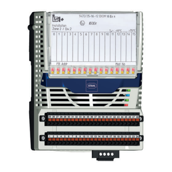
Seite 9: Funktion Und Geräteaufbau
16 nicht-eigensicheren Digitalsignalen an das IS1+ Remote I/O System. Alle Kanäle sind paarweise als Eingang für NAMUR-Initiatoren (EN 60947-5-6), 3-Leiter-PNP-Initiatoren (mit 24-V-Versorgung) sowie passive Kontakte und für Magnetventile (24 V / 0,5 A) parametrierbar. Die externe Versorgung für 3-Leiter-Initiatoren und Magnetventile erfolgt durch eine separate Klemme an der Vorderseite des Moduls. -
Seite 10: De 4.2 Geräteaufbau
Sicherungsschrauben Steckbare Klemme Steckbare Klemme X0 mit zwei Sicherungsschrauben Schutzabdeckung IP30 Schutzabdeckung für steckbare Klemme X0 Brücke Brücke zur Deaktivierung des Anlagen-AUS Digital Input Output Modul 24 V 230244 / 947260310010 für Zone 2 Ex n 2017-02-28·BA00·III·de·00 Reihe 9472/35... -
Seite 11: Technische Daten
1 k Ω 3-Leiter-PNP- Initiator Spannung für > 60 % * U (externe Versorgungsspannung) Spannung für < 55 % * U (externe Versorgungsspannung) 230244 / 947260310010 Digital Input Output Modul 24 V 2017-02-28·BA00·III·de·00 für Zone 2 Ex n Reihe 9472/35... - Seite 12 I Ausgangs- (externe Versorgungsspannung) -0,7 V spannung Ausgangsstrom 30 mA ... 0,5 A pro Kanal (elektronisch begrenzt) Summenstrom siehe Umgebungstemperatur der Ausgänge Digital Input Output Modul 24 V 230244 / 947260310010 für Zone 2 Ex n 2017-02-28·BA00·III·de·00 Reihe 9472/35...
- Seite 13 ) 1800 V AC I/O-Kanälen/ Hilfsenergie Zwischen ) 1800 V AC I/O-Kanälen / Systemkom- ponenten Zwischen ) 1800 V AC I/O-Kanälen / Erde (PA) 230244 / 947260310010 Digital Input Output Modul 24 V 2017-02-28·BA00·III·de·00 für Zone 2 Ex n Reihe 9472/35...
- Seite 14 Ausgänge "Aus" Unterspannung Max. 90 mA Stromaufnahme Max. < 2,2 W Leistungsaufnahme Max. Eingang: < 1,4 W Verlustleistung Ausgang: < 5,4 W Digital Input Output Modul 24 V 230244 / 947260310010 für Zone 2 Ex n 2017-02-28·BA00·III·de·00 Reihe 9472/35...
- Seite 15 Mechanische Daten Schutzart (IEC 60529) IP30 Modulgehäuse Polyamid 6GF Brandfestigkeit (UL-94) Abmessungen L = 139,5 mm, B = 96,5 mm, H = 64 mm 230244 / 947260310010 Digital Input Output Modul 24 V 2017-02-28·BA00·III·de·00 für Zone 2 Ex n Reihe 9472/35...
- Seite 16 Montage / Installation Einbaulage waagrecht oder senkrecht (Betriebsanleitung beachten) Montageart auf 35 mm DIN Schiene NS 35/15 (DIN EN 60715) Weitere technische Daten, siehe www.stahl-ex.com. Digital Input Output Modul 24 V 230244 / 947260310010 für Zone 2 Ex n 2017-02-28·BA00·III·de·00 Reihe 9472/35...
-
Seite 17: Projektierung
Anschlussbelegung steckbare Klemme X0 Dient zum Anschluss einer externen Hilfsenergie zur Versorgung von 3-Leiter-PNP-Initiatoren (DI) oder Magnetventilen (24 V / 0,5 A) (DO), ebenfalls sind zwei Klemmen für den "Anlagen-AUS" vorhanden. Werden die Klemmen 3 und 4 für "Anlagen- AUS" nicht genutzt, sind sie zu brücken (Brücke ist im Lieferumfang enthalten!). -
Seite 18: Anschlussbelegung Steckbare Klemme X1 Und X2
→ Eingang (...15) 18131E00 Eine Parallelschaltung von Ausgängen zur Stromerhöhung ist nicht zulässig! Nur 3-Leiter-Näherungsschalter PNP anschließen. Ein Anschluss NPN ist nicht erlaubt! Digital Input Output Modul 24 V 230244 / 947260310010 für Zone 2 Ex n 2017-02-28·BA00·III·de·00 Reihe 9472/35... -
Seite 19: Betriebsmodus "Frequenz" Oder "Zähler
• Bei Einsatz in Zone 2 und im sicheren Bereich ist ein Gehäuse mit mindestens IP54 erforderlich. • Bei Einsatz in Zone 22 ist ein Gehäuse mit mindestens IP64 erforderlich. 230244 / 947260310010 Digital Input Output Modul 24 V 2017-02-28·BA00·III·de·00 für Zone 2 Ex n Reihe 9472/35... -
Seite 20: De 8.1 Maßangaben / Befestigungsmaße
Feldverkabelung auf möglichst kurzem Weg mit der Montageplatte zu verbinden! Anleitung "Erdung und Schirmung" beachten! Maßangaben / Befestigungsmaße Maßzeichnungen (alle Maße in mm [Zoll]) – Änderungen vorbehalten 128,5 [5,06] 39,50 17625E00 Digital Input Output Modul 24 V 230244 / 947260310010 für Zone 2 Ex n 2017-02-28·BA00·III·de·00 Reihe 9472/35... -
Seite 21: Montage / Demontage, Gebrauchslage
Stromkreisen zu gewährleisten, gegebenenfalls Trennwand (220101) auf benachbartes Ex i Modul montieren oder Leerplatz zwischen Ex i und nicht Ex i Modulen vorsehen. 230244 / 947260310010 Digital Input Output Modul 24 V 2017-02-28·BA00·III·de·00 für Zone 2 Ex n Reihe 9472/35... -
Seite 22: Montage Der Ip30-Abdeckung
• Steckbare Klemmen X0, X1 und X2 auf Modul stecken und mit Schrauben gegen Lockern sichern (Anzugsdrehmoment 0,5 ... 0,6 Nm). • IP30-Abdeckung auf X0 anbringen (siehe oben). Digital Input Output Modul 24 V 230244 / 947260310010 für Zone 2 Ex n 2017-02-28·BA00·III·de·00... - Seite 23 14 (-) 21 (-) 30 (-) 45 (-) 15 (+) 23 (+) 31 (+) 47 (+) 16 (-) 24 (-) 32 (-) 48 (-) 230244 / 947260310010 Digital Input Output Modul 24 V 2017-02-28·BA00·III·de·00 für Zone 2 Ex n Reihe 9472/35...
-
Seite 24: Installation
• Gegebenenfalls Trennwand auf das benachbarte Ex i Modul einrasten. • Steckbare Klemme X0, X1 und X2 auf Modul stecken und mit Schrauben gegen Lockern sichern (Anzugsdrehmoment 0,5 … 0,6 Nm). • IP30-Abdeckung anbringen. Digital Input Output Modul 24 V 230244 / 947260310010 für Zone 2 Ex n 2017-02-28·BA00·III·de·00... -
Seite 25: Inbetriebnahme
16 x LED gelb Anzeige Signalzustand Feldstromkreise 16 x LED Kurzschluss oder Leitungsunterbrechung im Feldstromkreis LED "24 V" grün/ grün: 24 V vorhanden (18 ... 32 V) gelb gelb: "Anlagen-AUS" aktiv LED "M/S" blau Wartungsbedarf oder Umgebungstemperatur zu hoch LED "RUN"... - Seite 26 Externe Versorgung an Externe Versorgungsspannung an Klemme erloschen Klemme X0 außerhalb des X0 überprüfen Spannungsbereichs <18 V oder >32 V LED "24 V" leuchtet gelb "Anlagen-AUS" aktiviert • Prüfen, ob Klemme und Brücke (korrekt) installiert wurde • Klemme X0 gegebenenfalls deaktivieren...
-
Seite 27: Instandhaltung, Wartung, Reparatur
Instandhaltung, Wartung, Reparatur Wenn sich der Fehler mit den genannten Vorgehensweisen nicht beheben lässt: • An R. STAHL Schaltgeräte GmbH wenden. Zur schnellen Bearbeitung folgende Angaben bereithalten: • Typ und Seriennummer des Geräts • DCS/SPS • Protokoll • Revisions-Nr/Firmware-Version • Kaufdaten •... -
Seite 28: Reparatur
R. STAHL Schaltgeräte GmbH ausführen lassen. 11.4 Rücksendung • Rücksendung bzw. Verpackung der Geräte nur in Absprache mit R. STAHL durchführen! Dazu mit der zuständigen Vertretung von R. STAHL Kontakt aufnehmen. Für die Rücksendung im Reparatur- bzw. Servicefall steht der Kundenservice von R. -
Seite 29: Entsorgung
Fehlfunktion oder Geräteschaden durch den Einsatz nicht originaler Bauteile. Nichtbeachten kann Sachschaden verursachen! • Nur Original-Zubehör und Original-Ersatzteile der R. STAHL Schaltgeräte GmbH verwenden. Zubehör und Ersatzteile, siehe Datenblatt auf Homepage www.stahl-ex.com. 230244 / 947260310010 Digital Input Output Modul 24 V 2017-02-28·BA00·III·de·00 für Zone 2 Ex n...