Herunterladen Inhalt Inhalt Diese Seite drucken
Stahl IS1plus Betriebsanleitung
Vorschau ausblenden Andere Handbücher für IS1plus:
Inhaltsverzeichnis

Werbung

Verfügbare Sprachen

Verfügbare Sprachen

IS1+ Power Modul für
Zone 2 / Division 2
Reihe 9445/35
Betriebsanleitung
Additional languages www.r-stahl.com
DE
DE
DE
DE
DE
DE
DE
DE
DE
DE
DE
DE
DE
DE
DE
DE
DE
DE
DE
DE
DE
DE
DE
DE
DE
DE

Werbung

Kapitel

Inhaltsverzeichnis

Fehlerbehebung

loading

Inhaltszusammenfassung für Stahl IS1plus

  • Seite 1 Betriebsanleitung Additional languages www.r-stahl.com IS1+ Power Modul für Zone 2 / Division 2 Reihe 9445/35...
  • Seite 2: Inhaltsverzeichnis

    Inhaltsverzeichnis Allgemeine Angaben ...................3 Hersteller ......................3 Zu dieser Betriebsanleitung ................3 Weitere Dokumente ....................3 Konformität zu Normen und Bestimmungen ............3 Erläuterung der Symbole ..................4 Symbole in der Betriebsanleitung ...............4 Symbole am Gerät ....................4 Sicherheit ......................5 Bestimmungsgemäße Verwendung ..............5 Qualifikation des Personals ................5 Restrisiken ......................6 Transport und Lagerung ..................8 Produktauswahl und Projektierung ..............8...
  • Seite 3: Allgemeine Angaben

     Betriebsanleitung während der Lebensdauer des Geräts aufbewahren.  Betriebsanleitung dem Bedien- und Wartungspersonal jederzeit zugänglich machen.  Betriebsanleitung an jeden folgenden Besitzer oder Benutzer des Geräts weitergeben.  Betriebsanleitung bei jeder von R. STAHL erhaltenen Ergänzung aktualisieren. ID-Nr.: 264697 / 944560310010 Publikationsnummer: 2018-09-27·BA00·III·de·01...
  • Seite 4: Erläuterung Der Symbole

    Erläuterung der Symbole Erläuterung der Symbole Symbole in der Betriebsanleitung Symbol Bedeutung Hinweis zum leichteren Arbeiten GEFAHR! Gefahrensituation, die bei Nichtbeachtung der Sicherheitsmaßnahmen zum Tod oder zu schweren Verletzungen mit bleibenden Schäden führen kann. WARNUNG! Gefahrensituation, die bei Nichtbeachtung der Sicherheitsmaßnahmen zu schweren Verletzungen führen kann.
  • Seite 5: Sicherheit

    Normen und Bestimmungen umfasst. Für Tätigkeiten in explosionsgefährdeten Bereichen sind weitere Kenntnisse erforderlich! R. STAHL empfiehlt einen Kenntnisstand, der in folgenden Normen beschrieben wird: • IEC/EN 60079-14 (Projektierung, Auswahl und Errichtung elektrischer Anlagen) • IEC/EN 60079-17 (Prüfung und Instandhaltung elektrischer Anlagen) •...
  • Seite 6: Restrisiken

    Umgebungsbedingungen (siehe Kapitel "Technische Daten") berücksichtigen.  Gerät nicht belasten.  Verpackung und Gerät auf Beschädigung prüfen. Beschädigungen umgehend an R. STAHL melden. Beschädigtes Gerät nicht in Betrieb nehmen.  Gerät in Originalverpackung, trocken (keine Betauung), in stabiler Lage und sicher vor Erschütterungen lagern.
  • Seite 7  Nur kompatible Komponenten anschließen (Remote I/O-System IS1+/IS1). Im Zweifelsfall Rücksprache mit R. STAHL halten.  Reparaturen am Gerät nur durch R. STAHL durchführen lassen.  Gerät nur mit feuchtem Tuch und ohne kratzende, scheuernde oder aggressive Reinigungsmittel oder Lösungen schonend reinigen.
  • Seite 8: Transport Und Lagerung

    Transport und Lagerung 3.3.2 Beschädigung elektrischer Komponenten Empfindliche elektronische Bauteile können durch elektrostatische Entladung (ESD) beschädigt werden.  Vor dem Kontakt mit dem Gerät an einem geerdeten metallischen Körper entladen.  Direkte Berührung von Steckverbindern oder Kontakten der Modulsteckplätze vermeiden. ...
  • Seite 9: Redundanz

    Produktauswahl und Projektierung Projektierungsvorgaben in Abhängigkeit der Umgebungstemperatur Befestigung je nach maximaler Umgebungstemperatur ausrichten, siehe Kapitel "Technische Daten". Update/Austausch von Modulen • Kapitel "Austausch und Upgrade des Moduls" beachten. Redundanz Das IS1+ Remote I/O-System kann je nach Kommunikationsprotokoll auch redundant ausgeführt werden.
  • Seite 10: Montage Und Installation

    Montage und Installation Montage und Installation Montage / Demontage  Gerät sorgfältig und nur unter Beachtung der Sicherheitshinweise (siehe Kapitel "Sicherheit") montieren.  Folgende Einbaubedingungen und Montageanweisungen genau durchlesen und exakt befolgen. 6.1.1 Gebrauchslage  Sockel ausschließlich wie folgt montieren: •...
  • Seite 11: Austausch Und Upgrade Des Moduls

    Montage und Installation  Sockel montieren (siehe Betriebsanleitung 9496/35).  Power Modul unten in den Sockel einhängen (1) und einschwenken (2).  Prüfen, ob die Feder (1) vorhanden ist. Nur so ist eine korrekte Wärmeableitung über den Sockel gewährleistet.  Power Modul mit Sicherungsschraube befestigen. Sicherungsschraube festziehen (3) (Anzugsdrehmoment 1,5 ...
  • Seite 12: Upgrade Der Is1 Profibus Cpm Reihe 9440/15 Auf

    Montage und Installation 6.2.2 Upgrade der IS1 PROFIBUS CPM Reihe 9440/15 auf IS1+ CPU 9442/35 und Power Modul 9445/35 und Sockel 9496/35  Stromversorgung der IS1 Remote I/O-Station (CPM 9440/15) abschalten.  Rändelschrauben am rückseitigen Hilfsenergiestecker von CPM 9440/15 lösen und Stecker abziehen.
  • Seite 13: Stecker Für Hilfsenergie Anschließen / Trennen

    Parametrierung und Inbetriebnahme 6.3.1 Stecker für Hilfsenergie anschließen / trennen HINWEIS! Nichtbeachten kann zu Sachschäden führen.  Sicherstellen, dass die Versorgungsspannung 60 V DC (SELV/PELV) nicht überschreitet. Anschließen  Bei geschlossener Steckermechanik (siehe Abbildung unten) des blauen Hilfsenergie- steckers mit Anschlussleitung (als Zubehör erhältlich) auf die Kontakte X1 des Moduls 9445/35 ansetzen und kraftvoll aufstecken.
  • Seite 14: Betrieb

    Betrieb Betrieb Betrieb  Zum Betrieb des Geräts die Informationen im Kapitel "Bestimmungsgemäße Verwendung" und "Parametrierung und Inbetriebnahme" beachten. Nach dem Einschalten des Systems überprüft die CPU die Firmware-Versionen. Sollte im Power Modul eine ältere Version als in der CPU installiert sein, erfolgt automatisch ein Update auf die neue Version.
  • Seite 15 Power Modul tauschen (wenn "PWR IN" leuchtet) Wenn sich der Fehler mit den genannten Vorgehensweisen nicht beheben lässt:  An R. STAHL Schaltgeräte GmbH wenden. Zur schnellen Bearbeitung folgende Angaben bereithalten: • Typ und Seriennummer des Geräts • DCS/SPS • Protokoll •...
  • Seite 16: Instandhaltung, Wartung, Reparatur

     Reparaturen am Gerät nur durch R. STAHL durchführen lassen. Rücksendung  Rücksendung bzw. Verpackung der Geräte nur in Absprache mit R. STAHL durchführen! Dazu mit der zuständigen Vertretung von R. STAHL Kontakt aufnehmen. Für die Rücksendung im Reparatur- bzw. Servicefall steht der Kundenservice von R. STAHL zur Verfügung.
  • Seite 17: Reinigung

    Zubehör und Ersatzteile HINWEIS! Fehlfunktion oder Geräteschaden durch den Einsatz nicht originaler Bauteile. Nichtbeachten kann zu Sachschäden führen.  Nur Original-Zubehör und Original-Ersatzteile der R. STAHL Schaltgeräte GmbH (siehe Datenblatt) verwenden. 264697 / 944560310010 IS1+ Power Modul für Zone 2 / Division 2 2018-09-27·BA00·III·de·01...
  • Seite 18: 14.1 Technische Daten

    Anhang A Anhang A 14.1 Technische Daten Explosionsschutz Global (IECEx) IECEx PTB 17.0042 X Ex ec [ia Ga, ib Gb] IIC T4 Gc Europa (ATEX) PTB 17 ATEX 2026 X E II (1)G (2)G 3G Ex ec [ia Ga, ib Gb] IIC T4 Gc Bescheinigungen und Zulassungen Bescheinigungen IECEx, ATEX, EAC, cFMus (USA, Kanada)
  • Seite 19 Anhang A Technische Daten Galvanische Trennung Prüfspannung gemäß Norm EN 60079-11 zwischen 1500 V AC Hilfsenergie und BusRail / CPU / Sockel Elektromagnetische Geprüft nach folgenden Normen und Vorschriften: Verträglichkeit EN 61326-1 (2013) IEC 61000-4-1...6, NAMUR NE 21 Elektrischer Anschluss Anschluss der 2-polig über steckbare Klemme mit Aderleitung 3 m;...
  • Seite 20 Power Modul 9445/35 nur auf den Sockel 9496/35 aufstecken Einbaulage horizontal oder vertikal (Betriebsanleitung des Sockels 9496/35 beachten) Ausführung Schrauben Torx 20 Weitere technische Daten, siehe www.r-stahl.com. IS1+ Power Modul für Zone 2 / Division 2 264697 / 944560310010 Reihe 9445/35 2018-09-27·BA00·III·de·01...
  • Seite 21: 15.1 Geräteaufbau

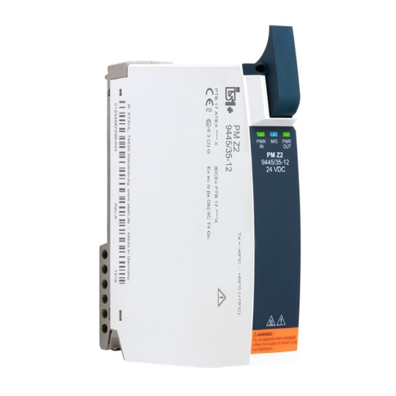
    Anhang B Anhang B 15.1 Geräteaufbau Gerätelement Beschreibung Sicherungs- Sicherungsschrauben schrauben für mechanischen Steckverbinder Sicherungs- Torx T20 zum schraube Befestigen am Sockel Hilfsenergie Mechanische Anschluss- Steckverbinder mit kontakte X1 Sicherungsschrauben und Aderleitungen LEDs LEDs zur Status- bzw. Fehleranzeige des Power Moduls 20020E00 Beschriftung Angaben zum Modul...
  • Seite 22: 15.2 Maßangaben / Befestigungsmaße

    Anhang B 15.2 Maßangaben / Befestigungsmaße Maßzeichnungen (alle Maße in mm [Zoll]) – Änderungen vorbehalten 170 [6,69] 155 [6,10] 19757E00 Power Modul 9445/35 18 [7, 66 6,54 67 6,57 19756E00 Power Modul 9445/35 mit Sockel 9496/35 IS1+ Power Modul für Zone 2 / Division 2 264697 / 944560310010 Reihe 9445/35 2018-09-27·BA00·III·de·01...
  • Seite 23 Operating instructions Additional languages www.r-stahl.com IS1+ power module for Zone 2 / Division 2 Series 9445/35...
  • Seite 24 Contents General Information ....................3 Manufacturer .......................3 About these Operating Instructions ..............3 Further Documents .....................3 Conformity with Standards and Regulations ............3 Explanation of the Symbols ................4 Symbols in these Operating Instructions ............4 Symbols on the Device ..................4 Safety ........................5 Intended Use .......................5 Personnel Qualification ..................5 Residual Risks ....................6 Transport and Storage ..................8...
  • Seite 25: General Information

    • Operating instructions for the Ethernet CPU and 9441/15 power module For documents in additional languages, see www.r-stahl.com. Conformity with Standards and Regulations • Certificates and EU Declaration of Conformity: www.r-stahl.com. • The device has IECEx approval. See IECEx homepage: http://iecex.iec.ch/ to view the certificate.
  • Seite 26: Explanation Of The Symbols

    Explanation of the Symbols Explanation of the Symbols Symbols in these Operating Instructions Symbol Meaning Tip for making work easier DANGER! Dangerous situation which can result in fatal or severe injuries causing permanent damage if the safety measures are not complied with.
  • Seite 27: Safety

    Specialists who perform these tasks must have a level of knowledge that meets applicable national standards and regulations. Additional knowledge is required for tasks in hazardous areas! R. STAHL recommends having a level of knowledge equal to that described in the following standards: •...
  • Seite 28: Residual Risks

    (see the "Technical data" chapter).  Do not place any load on the device.  Check the packaging and the device for damage. Report any damage to R. STAHL immediately. Do not commission a damaged device.  Store the device in its original packaging in a dry place (with no condensation), and make sure that it is stable and protected against the effects of vibrations and knocks.
  • Seite 29  Only connect compatible components (IS1+/IS1 Remote I/O system). When in doubt, consult with R. STAHL.  Repair work on the device must be performed only by R. STAHL.  Gently clean the device only with a damp cloth and without scratching, abrasive or aggressive cleaning agents or solutions.
  • Seite 30: Transport And Storage

    Transport and Storage 3.3.2 Damage to electrical Components Sensitive electronic components can be damaged by electrostatic discharge (ESD).  Before making contact with the device, discharge the charge to an earthed metal body.  Avoid direct contact with connectors or the contacts on the module slots. ...
  • Seite 31: Redundancy

    Product Selection and Project Engineering Project engineering specifications depending on the ambient temperature Adjust mounting processes based on the maximum ambient temperature, see the "Technical Data" chapter. Updating/replacing modules • Observe the "Replacing and upgrading the module" chapter. Redundancy The IS1+ Remote I/O system can also be implemented redundantly based on the communication protocol.
  • Seite 32: Mounting And Installation

    Mounting and Installation Mounting and Installation Mounting / Dismounting  Mount the device carefully and only in accordance with the safety notes (see Chapter "Safety").  Read through the following installation conditions and assembly instructions carefully and follow them precisely. 6.1.1 Operating Position ...
  • Seite 33: Replacing And Upgrading The Module

    Mounting and Installation  Mount the base (see 9496/35 operating instructions).  Hang (1) the power module in the bottom of the base and swivel it inward (2).  Check whether the spring (1) is present. This is the only way to guarantee that heat is dissipated correctly across the base. ...
  • Seite 34: Installation

    Mounting and Installation 6.2.2 Upgrade of the IS1 9440/15 PROFIBUS CPM Series to IS1+ 9442/35 CPU + 9445/35 Power Module + 9496/35 Base  Switch off the power supply to the IS1 Remote I/O Station (9440/15 CPM).  Unscrew the knurled screws on the auxiliary power plug of 9440/15 CPM on the reverse side and disconnect the plug.
  • Seite 35: Parameterization And Commissioning

    Parameterization and Commissioning 6.3.1 Plug for connecting/disconnecting the Auxiliary Power NOTICE! Non-compliance can result in material damage.  Make sure the 60 V DC (SELV/PELV) supply voltage is not exceeded. Connecting  If the plug mechanism (see figure below) of the blue auxiliary power plug with connection cable (available as accessories) is closed, place it against the X1 contacts of the 9445/35 module and use force to push it on.
  • Seite 36: Operation

    Operation Operation Operation  For device operation, observe the information in the "Intended Use" and "Parameterisation and Commissioning" chapters. After the system is switched on, the CPU checks the firmware versions. If the power module has a version installed that is older than the version installed in the CPU, it will be updated to the new version automatically.
  • Seite 37 (if "PWR IN" is lit) If the error cannot be eliminated using the specified procedures:  Contact R. STAHL Schaltgeräte GmbH. For rapid processing, have the following information ready: • Type and serial number of the device •...
  • Seite 38: Maintenance, Overhaul, Repair

     Only return or package the devices after consulting R. STAHL! Contact the responsible representative from R. STAHL. R. STAHL's customer service is available to handle returns if repair or service is required.  Contact customer service personally.  Go to the www.r-stahl.com website.
  • Seite 39: Cleaning

    Accessories and Spare Parts NOTICE! Malfunction or damage to the device due to the use of non-original components. Non-compliance can result in material damage.  Use only original accessories and spare parts from R. STAHL Schaltgeräte GmbH (see data sheet). 264697 / 944560310010 IS1+ power module for Zone 2 / Division 2 2018-09-27·BA00·III·en·01...
  • Seite 40: Annex A

    Annex A Annex A 14.1 Technical Data Explosion Protection Global (IECEx) IECEx PTB 17.0042 X Ex ec [ia Ga, ib Gb] IIC T4 Gc Europe (ATEX) PTB 17 ATEX 2026 X E II (1)G (2)G 3G Ex ec [ia Ga, ib Gb] IIC T4 Gc Certifications and certificates Certificates IECEx, ATEX, EAC, cFMus (USA, Canada)
  • Seite 41 Annex A Technical Data Galvanic separation Test voltage acc. to standard EN 60079-11 Between the 1500 V AC auxiliary power and BusRail / CPU / base Electromagnetic Tested to the following standards and regulations: compatibility EN 61326-1 (2013) IEC 61000-4-1 to 61000-4-6, NAMUR NE 21 Electrical connection Connection of 2-pole via a pluggable terminal with a 3 m single core;...
  • Seite 42 Only connect the 9445/35 power module to the 9496/35 base Mounting position Horizontal or vertical (observe the 9496/35 base operating instructions) Screw version Torx 20 For further technical data, see www.r-stahl.com. IS1+ power module for Zone 2 / Division 2 264697 / 944560310010 Series 9445/35 2018-09-27·BA00·III·en·01...
  • Seite 43: Annex B

    Annex B Annex B 15.1 Device Design Device Description component Safety screws Safety screws for mechanical plug connectors Safety screw Torx T20 for fastening components to the base Auxiliary power Mechanical plug of X1 connector connector with contacts safety screws and single cores LEDs LEDs for status or...
  • Seite 44: 15.2 Dimensions / Fastening Dimensions

    Annex B 15.2 Dimensions / Fastening Dimensions Dimensional drawings (all dimensions in mm [inches]) – Subject to modification 170 [6,69] 155 [6,10] 19757E00 9445/35 power module 18 [7, 66 6,54 67 6,57 19756E00 9445/35 power module with 9496/35 base IS1+ power module for Zone 2 / Division 2 264697 / 944560310010 Series 9445/35 2018-09-27·BA00·III·en·01...
  • Seite 46 Examples for System Topology interfacing The IS1+ Remote I/O System is a DIN rail mounted system designed Automation control systems with DIV 2 / Zone 2 to record and output process control signals between hazardous installation of IS1+ Remote I/O System: location transducers and sensors and a nonhazardous location automation system.
  • Seite 47 2018 08.03. Bagusch IS1+ Remote I/O System Kaiser for CL I, DIV 2 / Zone 2 2 of 2 Overview 9400 6 031 006 1...
  • Seite 48 Class I, DIV 2 / Zone 2 Installation The CPU Module Type 9442/35-10-00 and Power Module 9445/35-12 for connection to I/O Modules located in with the Socket 9496/35-03-00 are nonincendive apparatus for Class I, II, III, Division 2, Group A-G, installation in Class I, Division 2, Group A-D or Class I, Zone 2, Group or Class I, Zone 2, Group IIC/IIB IIC/IIB hazardous location;...

Inhaltsverzeichnis