Helios MultiVent MV EC-Serie Montage- Und Betriebsvorschrift
Ec-rohrventilatoren
Vorschau ausblenden
Andere Handbücher für MultiVent MV EC-Serie:
- Montage- und betriebsvorschrift (32 Seiten)

Verwandte Anleitungen für Helios MultiVent MV EC-Serie


Inhaltszusammenfassung für Helios MultiVent MV EC-Serie
- Seite 1 Helios Ventilatoren MONTAGE- UND BETRIEBSVORSCHRIFT INSTALLATION AND OPERATING INSTRUCTIONS EC-Rohrventilatoren EC In-line Fans MultiVent ® MV EC..
-
Seite 2: Inhaltsverzeichnis
DEUTSCH Inhaltsverzeichnis KAPITEL 1 ALLGEMEINE MONTAGE- UND BETRIEBSHINWEISE ........Seite 1 Wichtige Informationen . -
Seite 3: Kapitel 1 Allgemeine Montage- Und Betriebshinweise
Wenn die nachfolgenden Ausführungen nicht beachtet werden, entfällt unsere Gewährleistung. Gleiches gilt für Haf- tungsansprüche an den Hersteller. Der Gebrauch von Zubehörteilen, die nicht von Helios empfohlen oder angeboten werden, ist nicht statthaft. Even tuell auftretende Schäden unterliegen nicht der Gewährleistung. -
Seite 4: Geräuschpegel
Reicht der Strom einer EC-Versorgung nicht aus, kann eine bauseits zu stellende ausreichende externe 10 V DC eingesetzt werden (vom Netz galvanisch getrennt). Alternativ kann für vielfältige Steuerungsaufgaben das Modul „EUR EC“ von Helios eingesetzt werden. Die Steuerleitung muss das gleiche Isolationsniveau wie die Netzleitung haben tor und die Elektronik ausgerüstet. -
Seite 5: Kapitel 2 Serienteile Und Zubehör
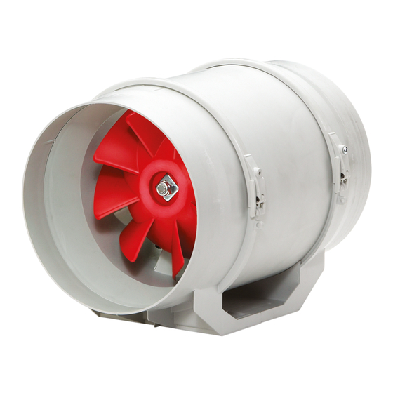
Montage- und Betriebsvorschrift ® MultiVent MV EC.. Serienteile zu MultiVent MV EC.. KAPITEL 2 Abb.5 SERIENTEILE UND ZUBEHÖR ë ò Gehäuse aus schlag- und korrosionsfestem Kunststoff ù Hochleistungslaufrad und ä Nachleitrad aus Kunststoff optimiert für hohe Druck- und Volumenleistung ë Klemmenkasten außen am ü... -
Seite 6: Kapitel 3 Aufstellung/Montage
Montage- und Betriebsvorschrift ® MultiVent MV EC.. Montage KAPITEL 3 Die Ventilatoren werden serienmäßig als komplette Einheit, d.h. anschlussfertig geliefert. Sie können in beliebiger Achslage eingebaut werden – waagerecht, – senkrecht, – schräg (s. Abb. 11). Die Ventilatoren sind durch öffnen der AUFSTELLUNG/MONTAGE Spannbügel (s. -
Seite 7: Wichtige Hinweise
Montage- und Betriebsvorschrift ® MultiVent MV EC.. Einbau Variable Positionierung des Ventilators bzw. Klemmenkasten möglich, je nach Einbaubedingung (s. Abb. 16). Abb.16 Wand – Körperschallübertragung Es ist darauf zu achten, dass Körperschallübertragungen auf Ge bäude und Rohrsystem vermieden werden! Die MultiVent ®... -
Seite 8: Kapitel 4 Inbetriebnahme
Montage- und Betriebsvorschrift ® MultiVent MV EC.. Wird eine Fehlerstrom-Schutzeinrichtung in die Zuleitung des EC Ventilators verbaut, muss die Fehlerstrom-Schut- zeinrichtung die folgenden technischen Merkmale aufweisen: Typ A oder B mit einem Bemessungsdifferenzstrom von 30 mA. Der EC Ventilator hat einen Ableitstrom von <= 3,5 mA, ermittelt nach DIN EN 50178 Bild 4. KAPITEL 4 Erstinbetriebnahme Vor der Erstinbetriebnahme sind folgende Punkte zu prüfen:... -
Seite 9: Schaltpläne Für Mv Ec
Montage- und Betriebsvorschrift ® MultiVent MV EC.. KAPITEL 7 Abb.19 SS-1194 SCHALTPLÄNE MV EC 125 für MV EC.. MV EC 160 MV EC 200 MV EC 250 Wechselstrom, 1~, 230 V, 50 Hz... - Seite 10 Montage- und Betriebsvorschrift ® MultiVent MV EC.. Abb.20 SS-1035...
- Seite 11 Montage- und Betriebsvorschrift ® MultiVent MV EC.. Abb.21 SS-1195 MV EC 315...
- Seite 24 HELIOS Ventilatoren GmbH + Co KG · Lupfenstraße 8 · 78056 VS-Schwenningen HELIOS Ventilateurs · Le Carré des Aviateurs · 157 avenue Charles Floquet · 93155 Le Blanc Mesnil Cedex CH HELIOS Ventilatoren AG · Tannstrasse 4 · 8112 Otelfingen GB HELIOS Ventilation Systems Ltd.