Inhaltsverzeichnis
Werbung
www.freeservicemanuals.info
Service
Manual
Sach-Nr./Part no.
72010-514.80
GV 400
(77400-010.51 / G.MD 0200) RP 10
GV 402
(77400-012.51 / G.MD 0900) RP 13
GV 410
(77400-110.51 / G.MD 1400) RP 10
GV 412
(77400-111.51 / G.MD 1900) RP 13
GV 400 OST
(77400-013.51 / G.MD 5600) RT130
RP 10 / RT 130
Änderungen vorbehalten
Subject to alteration
RP 13 / RT 230
SERVICE MANUAL
GV 400 OST, GV 411 OST
GV 430
MV 4005
MV 4105
GV 411 OST
PAL
Printed in Germany
VK 222
0793
*
GV 400, GV 402
GV 410, GV 412
MV 4005, MV 4105
(77400-310.51 / G.MD 2600) RP 13
(77400-044.51 / M.MD 0800) RP 10
(77400-144.51 / M.MD 1700) RP 13
(77400-112.51 / G.MD 5700) RT 230
SECAM OST
Service Manual Sach-Nr. 72010-514.80
Service Manual Part No.
It`s Free
GV 430
72010-514.80
Werbung
Inhaltsverzeichnis

Verwandte Anleitungen für Grundig GV400


Inhaltszusammenfassung für Grundig GV400
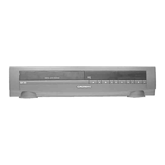
- Seite 1 www.freeservicemanuals.info It`s Free SERVICE MANUAL Service GV 400, GV 402 Manual GV 410, GV 412 GV 430 Sach-Nr./Part no. 72010-514.80 MV 4005, MV 4105 GV 400 OST, GV 411 OST GV 400 GV 430 (77400-010.51 / G.MD 0200) RP 10 (77400-310.51 / G.MD 2600) RP 13 GV 402 MV 4005...
-
Seite 2: Inhaltsverzeichnis
Bedieneinheit (MDCB1) ............4-19 Keyboard Control Unit (MDCB1) ..........4-19 Oszillogramme ................4-21 Oscillograms ................4-21 Laufwerk ..........5-1…5-10 Drive Mechanism ....... 5-1…5-10 Explosionszeichnungen Exploded Views and und Ersatzteilliste ......6-1…6-26 Spare Parts List ......... 6-1…6-26 1 - 2 GRUNDIG Service-Technik... -
Seite 3: Allgemeiner Teil
Geräteübersicht / Video Reocorder Overview Geräte-Bausteinübersicht Geräte-Feature-Übersicht Fernbedienung Table of Moduls Table of Features Remote Control GV 400 GV 402 GV 410 GV 412 GV 430 MV 4005 MV 4105 GV 400 OST GV 411 OST GRUNDIG Service-Technik 1 - 3... -
Seite 4: Meßgeräte / Meßmittel
Stabilisiertes Netzgerät Digital multimeter Stabilized power supply Millivoltmeter Frequenzzähler Millivoltmeter Frequency counter Beachten Sie bitte das Grundig Meßtechnik-Programm, das Sie unter Please note the Grundig Catalog "Test and Measuring Equipment" folgender Adresse erhalten: obtainable from: Grundig AG Grundig AG Geschäftsbereich Industrieelektronik Geschäftsbereich Industrieelektronik... - Seite 5 Panne du fer à souder Tweezers Lötzinn Punto de soldator Pinzetta Solder Pince brucelle Stagno Pinzas Soudure Estaño Kleber Adhesive Leiterplatte Adesivo P.C.B. Adhesif Piastra stampata Pegamento Circuit imprimé Placa de circuito impreso Fig. 1 Fig. 2 GRUNDIG Service-Technik 1 - 5...
-
Seite 6: Sicherheitsvorschriften
0701 (concernant les réparations) et VDE 0860 / IEC insulated from the supply circuit. 65 (concernant le type de produit)! Observe MOS components handling instructions when servicing! 1 - 6 GRUNDIG Service-Technik... -
Seite 7: Sicherheitsbestimmungen
In this case, the check of the leakage current is significant. - or the request of the user is that the restoration is not to be carried out, the operator of the product must be warned of the danger by a written warning. GRUNDIG Service-Technik 1 - 7... -
Seite 8: Prescriptions De Sécurité
Le fonctionnement est • Nettoyer les soudures avant de les renouveler. correct lorsque (Fig. 2): • Dégager les voies d’aération. ≤ 1mA pour U = 220V≈ fuite test Durée de la mesure: ≥ 1s. 1 - 8 GRUNDIG Service-Technik... - Seite 9 Heat - The appliance should be situated away from heat sources servicing should be referred to qualified service personnel . such as radiators, heat registers, stoves, or other appliances (including amplifiers) that produce heat. Items (x1) and (x2 ) apply only to receivers or tuners. GRUNDIG Service-Technik 1 - 9...
-
Seite 10: Behandlung Von Mos - Bauelementen
Prescription de soudure sur les circuits MOS • N´utiliser que des fers à souder basse tension isolés du secteur • Temps de soudre maximum : 5 secondes pour une température comprise entre 300 °C et 400 °C. 1 - 10 GRUNDIG Service-Technik... -
Seite 11: Abkürzungen
Display-Heizung (LOW) display heater (LOW) Tacho Wickelteller links tacho generator, left spindle Kopfimpuls 1 Video head pulse 1 video Kopfauswahl head select control Tacho Wickelteller rechts tacho generator, right spindle Init und Aufnahmesperre init/record protect GRUNDIG Service-Technik 1 - 11... -
Seite 12: Servicehinweise
(Fig. 5). – Release the locking lugs (Fig. 5). – Bedieneinheit abnehmen. – Withdraw the Keyboard Unit. – Gegebenenfalls Steckverbindung lösen. – Unplug the connector if necessary. Fig. 1 Fig. 2 Fig. 3 Fig. 4 GRUNDIG Service-Technik 1 - 29... -
Seite 13: Chassisplatte Ausbauen
Nach der Reparatur darauf achten, daß der Abschirmdeckel des On completion of the repairs take care that the shielding cover Netzteilbausteins sowie der Isolationsstreifen (Fig. 8) ange- and the isolating strip (Fig. 8) are refitted to the Power Supply bracht sind! Unit! 1 - 30 GRUNDIG Service-Technik... - Seite 14 8. Meßwerte und Oszillogramme 8. Measured Values and Oscillograms Bei den in den Schaltplänen und Oszillogrammen angegebenen The measured values given in the circuit diagrams and oscillograms Meßwerten handelt es sich um Näherungswerte! are approximates! GRUNDIG Service-Technik 1 - 31...
-
Seite 15: Servicehinweise
(Fig. 5). – Release the locking lugs (Fig. 5). – Bedieneinheit abnehmen. – Withdraw the Keyboard Unit. – Gegebenenfalls Steckverbindung lösen. – Unplug the connector if necessary. Fig. 1 Fig. 2 Fig. 3 Fig. 4 1 - 32 GRUNDIG Service-Technik... - Seite 16 Nach der Reparatur darauf achten, daß der Abschirmdeckel des On completion of the repairs take care that the shielding cover Netzteilbausteins sowie der Isolationsstreifen (Fig. 6) ange- and the isolating strip (Fig. 6) are refitted to the Power Supply bracht sind! Unit! GRUNDIG Service-Technik 1 - 33...
- Seite 17 8. Meßwerte und Oszillogramme 8. Measured Values and Oscillograms Bei den in den Schaltplänen und Oszillogrammen angegebenen The measured values given in the circuit diagrams and oscillograms Meßwerten handelt es sich um Näherungswerte! are approximates! 1 - 34 GRUNDIG Service-Technik...
-
Seite 18: Servicetestprogramm
Achtung: Nach dem Löschen bzw. dem Tausch des EEPROMs muß Attention: When erasing or replacing the EEPROM the video recorder das Gerät gemäß Kap. 3 - Abgleich abgeglichen werden. must be realigned as described in the alignment instructions, chap 3. GRUNDIG Service-Technik 1 - 35... - Seite 19 Schneller Vorlauf / Fast forward Schneller Rücklauf / Fast reverse Zeitlupe (1/6) / Slow (1/6) Zeitlupe (1/12) / Slow (1/12) Zeitlupe (1/24) / Slow (1/24) E-E-Betrieb / E-E-Mode Bereitschaft-Schacht oben / Standby eject Index next Index previous 1 - 36 GRUNDIG Service-Technik...
- Seite 20 A: AC, 2V/Div, 0,5s/Div B: AC, 2V/Div, 0,5s/Div Init Schalter / Init switch Fädeltacho-Impuls (FTA) Threading pulse (FTA) Cassette eingeschoben Wiedergabe / Play Cassette in Einfädeln / Thread in Cassette unten Halber Ladezustand Cassette down Half loaded GRUNDIG Service-Technik 1 - 37...
- Seite 21 – Taste "STAND-BY" drücken oder Gerät vom Netz trennen. – Press the "STAND-BY" button or disconnect the video recorder from the mains. Wiedergabe Bandende Aufnahme Play End of Tape Record Bandanfang Einfädeln Rückspulen Ausfädeln Beginning of Thread in Rewind Thread out tape 1 - 38 GRUNDIG Service-Technik...
-
Seite 22: Beschreibungen
Wiedergabeumschaltung, sowie die Freigabe der Aufsprechströme. and headwheel control. It controls the record/playback switching Ein interner Schwarz/Weiß-Bildgenerator erleichtert den Modulator- process and the release of the recording currents. abgleich. An internal black/white video generator facilitates adjustment of the modulator. GRUNDIG Service-Technik 2 - 1... - Seite 23 25Hz for the phase control and also the FG (frequency FG-/PG-Impulse zum Ablaufrechner IC7410-(4). generator) pulses of 450Hz for the speed control. From the connector F4-1 the FG/PG pulses are fed to the sequence control computer IC7410-(4). 2 - 2 GRUNDIG Service-Technik...
-
Seite 24: Bandservoregelung
(eg. station tuning data/ näle, Software-Abgleichwerte). Die Datenübertragung erfolgt über channels, software/adjustment values). The data is transferred via the den I C-Bus (SDA / SCL). C-bus (SDA / SCL). GRUNDIG Service-Technik 2 - 3... -
Seite 25: Chassisplatte - Empfangseinheit (Fv)
Band 1 Pin 13 = LOW, Pin 14 = LOW Pin 13 = HIGH, Pin 14 = LOW Band 3 Pin 13 = LOW, Pin 14 = HIGH Pin 13 = HIGH, Pin 14 = LOW 2 - 4 GRUNDIG Service-Technik... - Seite 26 The externally connected components of the deemphasis stage are EMPH) mit Wiedergabe-Amplitudeneinstellung und einen A/W-Schal- the R3037, C2019 and C2020. Adjustment of the playback amplitude ter zum Pin 3 des IC7051. Die äußere Beschaltung der Deemphasis- GRUNDIG Service-Technik 2 - 5...
- Seite 27 Die Funktion eines Kammfilters besteht darin, in einem Schaltungs- CF873-(4) by two lines periods for the PAL system and to add it to the zweig, CF873-(4), das jeweilige Signal bei PAL um 2 Zeilen zu 2 - 6 GRUNDIG Service-Technik...
- Seite 28 For the "LP" function, switchover of the record equalizing circuit is Für die Funktion "LP" wird die Umschaltung der Aufnahme-Entzerrung carried out by the switches EP CTL and LP CTL in IC7601. mit den Schaltern EP CTL und LP CTL im IC7601 durchgeführt. GRUNDIG Service-Technik 2 - 7...
- Seite 29 LOW level exists at Pin 2 so that further functions of the IC are dem Systemquarz Q1001 an Pin 13 / 14 abgeschaltet werden. switched off by the system quartz Q1001 at Pin 13 / 14. 2 - 8 GRUNDIG Service-Technik...
-
Seite 30: Ablaufsteuerung / Deckelektronik (De)
" und am Gerät die Taste " "drücken. – Bei erfolgreich durchgeführtem Abgleich schaltet das Gerät in den Standby-Betrieb. Bei nicht erfolgreich durchgeführtem Abgleich wirft das Gerät die Testcassette aus. Ursache:Testcassette, Kopfscheibe oder technischer Defekt (z.B. µC) GRUNDIG Service-Technik 3 - 1... -
Seite 31: Ablaufsteuerung / Deckelektronik (De)
Oszilloskop: . Kopfverstärker TP1 (Video current testpin) AV - Aufnahme Verbindung von IC7501-(40) mit +5V auftrennen. ± 4. Wiedergabe- Weißtestbild (Eigenaufnahme) wiedergeben. Amplitude mit R3039 (Y-PB LEVEL) auf 1,8V 0,05V amplitude, R3039 Oszilloskop: ....EURO-AV-Buchse, Kontakt 19 einstellen. 3 - 2 GRUNDIG Service-Technik... -
Seite 32: Standardton / Audio Linear (Al)
Während dem Anschließen des Gerätes an das Netz am len. Gerät gleichzeitig die Tasten " ", " " und " " drücken. Mit dem Massekabel den Steckerkontakt DC1-3 (SCL) so oft antippen bis im Display keine Segmente aktiv sind. GRUNDIG Service-Technik 3 - 3... -
Seite 33: Power Supply (Msm1)
– On successful adjustment the video recorder switches to stand-by. If the adjustment has not been carried out successfully the video recorder ejects the test cassette. Reason: Test cassette, headwheel or technical defect (eg. µC). 3 - 4 GRUNDIG Service-Technik... -
Seite 34: Family Board (Mfb)
AV recording. Disconnect IC7501-(40) from +5V. ± 4. Playback Playback a white test pattern (recorded with the machine) Set amplitude with R3039 (Y-PB LEVEL) to 1.8V 0.05V. Amplitude, R3039 Oscilloscope: ....EURO-AV socket, contact 19 GRUNDIG Service-Technik 3 - 5... -
Seite 35: Standard Sound / Audio Linear (Al)
", " " and " " on the video recorder while connecting it to the mains. With the earthing cable touch the plug contact DC1-3 (SCL) repeatedly until no segments are active in the display. 3 - 6 GRUNDIG Service-Technik... -
Seite 36: Wiring Diagram
HEHI +33V GNDM1 GNDM2 +8M2 +14M1 -28V +14A GNDA Component side Head amplifier HEAD-DRUM MEH2 MEH1 Display Control Component side * ... SIGNAL USED FOR SECAM SETS BCBL_9227 N.A. 9318 GRUNDIG Service-Technik 4 - 1 GRUNDIG Service-Technik 4 - 1... -
Seite 37: Block Circuit Diagram (Analog)
It`s Free Platinenabbildungen und Schaltpläne / Layout of PCBs and Circuit Diagrams Platinenabbildungen und Schaltpläne / Layout of PCBs and Circuit Diagrams Blockschaltplan / Block Circuit Diagram (Analog) 4 - 2 GRUNDIG Service-Technik 4 - 2 GRUNDIG Service-Technik... -
Seite 38: Block Circuit Diagram (Digital)
It`s Free Platinenabbildungen und Schaltpläne / Layout of PCBs and Circuit Diagrams Platinenabbildungen und Schaltpläne / Layout of PCBs and Circuit Diagrams Blockschaltplan / Block Circuit Diagram (Digital) GRUNDIG Service-Technik 4 - 3 GRUNDIG Service-Technik 4 - 3... - Seite 39 ISOLATION TRANSFORMER WHEN SERVICING to Pos 7210 DO NOT OPERATE WITHOUT CASE Pin 5 HOT GND CAUTION : LETHAL POTENTIALS AT PRIMARY .. OSCILLOGRAMS MSM1(SPH)_9310 VOLTAGES ARE MEASURED IN RECORD MODE N.A. 9318 4 - 4 GRUNDIG Service-Technik 4 - 4 GRUNDIG Service-Technik...
- Seite 40 ISOLATION TRANSFORMER WHEN SERVICING 9.4V 4.3V DO NOT OPERATE WITHOUT CASE CAUTION : LETHAL POTENTIALS AT PRIMARY COLD GND HOT GND MSM1(TDA)_9310 .. OSCILLOGRAMS N.A. 9318 VOLTAGES ARE MEASURED IN RECORD MODE GRUNDIG Service-Technik 4 - 5 GRUNDIG Service-Technik 4 - 5...
- Seite 41 9 0 3 2 6 5 0 8 9 1 0 2 2 7 5 0 9 0 3 6 3 5 1 1 1 5 1 3 5 1 7 4 - 6 GRUNDIG Service-Technik 4 - 6 GRUNDIG Service-Technik...
- Seite 42 7 4 0 6 7 5 0 1 7 7 0 7 3 5 1 5 7 7 0 5 7 4 0 7 7 5 0 0 7 5 0 6 GRUNDIG Service-Technik 4 - 7 GRUNDIG Service-Technik 4 - 7...
-
Seite 43: Family Board (Mfb)
MEASURED IN PLAYBACK MODE ...V to VS/IO to FV ...V MEASURED IN RECORD MODE .. O OSCILLOGRAMS Deckelectronic 9314 A.N. 9318 to DC 1 Operating Panel to SM 1 Power supply 4 - 8 GRUNDIG Service-Technik 4 - 8 GRUNDIG Service-Technik... -
Seite 44: Laufwerkplatte - Sensoreneinheit / Tape Deck Sensor Panel
STRIP 1005 STRIP 3602 RECP GNDD INIT INIT GNDM1 CREV 3600 6101 SFH409-2 +14M1 GNDD to Capstan Motor 3103 LIMIT 7101 7100 BC548B BC548B 3300 2001 10u/50V 3105 3104 GNDD STRIP 1007 Sen_9227 N.A. 9318 GRUNDIG Service-Technik 4 - 9... - Seite 45 3104 3105 3100 9002 1002 3401 1007 1003 7102 7106 1005 1004 6103 7104 3602 1006 3601 7105 3502 6104 3501 7105 3500 3600 6104 9001 WDS.3 8203 101 74512 RECP 0004 INIT 0003 SVHS 4 - 10 GRUNDIG Service-Technik...
- Seite 46 7714 E 7 7700 3704 3705 2701 LM358M 3707 100n 3706 0.6V 0.6V STROBE to DE MEASURED IN PLAYBACK MODE 1701 3708 MEASURED IN RECORD MODE 560k OSCILLOGRAMS Frontend 9314 A.N. 9318 GRUNDIG Service-Technik 4 - 11 GRUNDIG Service-Technik 4 - 11...
- Seite 47 7053 5VAS -28V1 +12A ...V MEASURED IN PLAYBACK MODE ENVC TRIV CSYNC ESPBH IPBV I8SC112 CROT MODON -28V1 +12A ...V MEASURED IN RECORD MODE .. OSCILLOGRAMS TO FV TO DE 4 - 12 GRUNDIG Service-Technik 4 - 12 GRUNDIG Service-Technik...
- Seite 48 +12A AMLR AMLP 3066 B16 7551 A27 3067 B17 9011 N17 Videosignalpr., In/Out 9314 3068 C16 3069 C16 A.N. 9318 TO AL 3070 C18 3071 B18 3072 C18 3073 C19 GRUNDIG Service-Technik 4 - 13 GRUNDIG Service-Technik 4 - 13...
- Seite 49 AEH1 Longplay AEH2 3611 3600 3603 2603 2604 3604 390k to Deck L3 ..V MEASURED IN PLAYBACK MODE ..V MEASURED IN RECORD MODE ..O OSCILLOGRAMS Audio linear 9314 A.N. 9318 4 - 14 GRUNDIG Service-Technik 4 - 14 GRUNDIG Service-Technik...
-
Seite 50: Head Amplifier (Lha)
7 3 0 1 3 3 0 1 C 1 3 3 0 2 C 1 3 3 0 3 C 1 3 3 0 4 C 1 L HA3 5875. 2 GRUNDIG Service-Technik 4 - 15 GRUNDIG Service-Technik 4 - 15... - Seite 51 3 8 1 3 B 1 3 0 0 1 A 1 3 8 3 1 C 1 LHA4 3 0 0 2 A 1 3 8 3 2 C 1 103 38300 5745. 2 4 - 16 GRUNDIG Service-Technik 4 - 16 GRUNDIG Service-Technik...
- Seite 52 3051 3050 HELO1 100E 3052 6050 HEHI 100E BZX55/C6V8 7102 STROBE VF-DISPLAY TIMER PROG START DATE STOP PSS**) to Deckelectronic F6 8-MT-75GK TEST INT2 Operating panel MDCG1 9314 N.A. 9318 GRUNDIG Service-Technik 4 - 17 GRUNDIG Service-Technik 4 - 17...
- Seite 53 6 0 1 2 3 0 1 2 3 0 1 1 9 0 1 8 2 0 5 1 1 9 3 2 7 1 0 2 9 0 1 9 4 - 18 GRUNDIG Service-Technik 4 - 18 GRUNDIG Service-Technik...
- Seite 54 3052 6050 HEHI 100E BZX55/C6V8 STROBE 5.3V 3006 CM1185G 100E 5.3V 3007 100E 4.3V 0.6V 3053 PSS**) to Deckelectronic F6 TEST INT2 Only for SECAM-sets Operating panel MDCB1 A.N. 9318 GRUNDIG Service-Technik 4 - 19 GRUNDIG Service-Technik 4 - 19...
- Seite 55 3 0 3 5 9 0 1 4 3 0 3 6 7 0 3 1 9 0 1 2 3 0 2 9 3 0 3 4 7 1 0 2 4 - 20 GRUNDIG Service-Technik 4 - 20 GRUNDIG Service-Technik...
-
Seite 56: Oscillograms
A: DC, 0.2 V/Div 0.2 ms/Div A: DC, 0.1 V/Div 0.2 us/Div A: DC, 0.5 V/Div 0.2 ms/Div IC 7551 Pin 4, VBS IC 7551 Pin 15, AMLR Tuner 1720 Pin 17 IC 7702 Pin 9, AFV < GRUNDIG Service-Technik 4 - 21... - Seite 57 A: DC, 1 V/Div, 0.5 ms/Div A: DC, 2 V/Div, 1 ms/Div A: DC, 0.2 V/Div, 10 ms/Div A: DC, 2 V/Div, 10 ms/Div Connector L9, 4 IC 7301 Pin 1,16,3 Connector L9,3 Connector L1, 6 PG/FG & 4 - 22 GRUNDIG Service-Technik...
-
Seite 58: Auswechseln Von Laufwerksteilen
Bei einer Änderung der Position des Cassettenschachtes (Lift) wäh- repairs, the compartment must be moved manually to the "Eject" rend der Reparatur muß dieser danach von Hand in die Position "Eject" position on completion of the repairs. gebracht werden. GRUNDIG Service-Technik 5 - 1... - Seite 59 – Fädelmotor entgegen dem Uhrzeigersinn drehen (Fig. 4), bis der – Turn the threading motor counterclockwise (Fig. 4) until the cassette Cassettenschacht abgesenkt ist. compartment is down. Fig. 2 Fig. 1 Fig. 3 5 - 2 GRUNDIG Service-Technik...
- Seite 60 Reel Pos. 20aJ Reel Pos. 20J Bremse links Zahnrad (2x) Bremse rechts Main break left Pos. 5K Gearwheel (2x) Pos.18J Main brake right Pos. 10K Schwenkrad Triggerschieber Fig. 5 Swivelling gear Pos. 17J,19J Trigger slider Pos. 4K GRUNDIG Service-Technik 5 - 3...
- Seite 61 (Fig. 6) unten befestigen. – Place the bracket (Pos. 102H) onto the shaft of gearwheel "A" and – Klammer (Pos. 102H) auf der Achse des Zahnrades "A" einrasten lock it in (Fig. 7). (Fig. 7). 5 - 4 GRUNDIG Service-Technik...
- Seite 62 When fitting the motor ensure that the threading motor locks into the eingerastet ist. front and rear bearing. Neigungswinkel-Einstellschraube Tilt setting screw Montageschraube B Mounting screw B Höhen-Einstellschraube Height setting screw Azimut-Einstellschraube Azimuth adjustment screw Fig. 10 Fig. 11 GRUNDIG Service-Technik 5 - 5...
- Seite 63 Nach Austausch des Fädelschlittens rechts muß der Bandlauf (Kap. 3.1) After replacing the threading roller unit (right), check and if necessary kontrolliert und gegebenenfalls eingestellt werden. readjust the tape transport (chapter 3.1). Pinzette Tweezers Fig. 14 5 - 6 GRUNDIG Service-Technik...
- Seite 64 Der Zusammenbau erfolgt durch Einrasten der Schnapphaken und Reassembly is carried out by snapping the snap hooks into place, and durch Einsetzen der Niete "B". inserting the rivet B. Fig. 16 GRUNDIG Service-Technik 5 - 7...
-
Seite 65: Fädelschlitten Links Und Rechts
TRIV as straight and flat as possible (Fig. 18). einstellen (Fig. 18). Videokopf Video head Band Tape Videospur Ansicht von der Bandoberseite Video track View to foil side Spurbild Video Track Diagram TRIV Trigger 20ms Fig. 18 5 - 8 GRUNDIG Service-Technik... - Seite 66 – Mit der Excenterschraube (Fig. 19) das Trackingsignal "TRIV"- – Play back the black/white part of the test cassette. Signal auf Maximum stellen (DC-gekoppelt). – With the eccentric screw (Fig.19) adjust the "TRIV" signal to maxi- mum voltage (DC-coupling). GRUNDIG Service-Technik 5 - 9...
- Seite 67 – The torquemeter must read 7mNm ±3mNm (70gf-cm ±30gf-cm). entgegen dem Uhrzeigersinn so lange drehen, bis der Wickelteller leicht durchrutscht (Fig. 21). – Wert am Drehmomentmesser muß 7mNm ±3mNm (70gf-cm ±30gf-cm) betragen. Pos. 41G Pos. 45A Fig. 22 Fig. 23 5 - 10 GRUNDIG Service-Technik...
- Seite 68 www.freeservicemanuals.info It`s Free 20aJ 44AB Öl / Oil (Sach-Nr. / Part No. 75988-002.35) Fett / Grease (Sach-Nr. / Part No. 75988-002.36) Isopropanol Fusselfreies Tuch / Fibrefree Tissue...
- Seite 69 104H 112E 105H 111B 110E 107E 109E 108E 113B 116 I 117 I 119E 120E 121E 123E 124E 122E 125E 128G Fett / Grease (Sach-Nr. / Part No. 75988-002.36) Isopropanol Fusselfreies Tuch / Fibrefree Tissue 6 - 2 GRUNDIG Service-Technik...
- Seite 70 It`s Free Explosionszeichnungen / Exploded Views 0008.000 0008.000 0007.000 0008.000 0005.000 0050.000 0060.000 0004.000 0040.000 0006.002 0006.001 0001.000 0070.000 0002.000 0006.000 0003.000 GRUNDIG Service-Technik 6 - 3...
- Seite 71 It`s Free Explosionszeichnungen / Exploded Views 0008.000 0008.000 0007.000 0008.000 0005.000 0050.000 0060.000 0004.000 0040.000 0006.002 0001.000 0006.001 0070.000 0002.000 0006.000 0003.000 6 - 4 GRUNDIG Service-Technik...
-
Seite 72: Ersatzteilliste List Of Spare Parts
www.freeservicemanuals.info It`s Free Ersatzteilliste Ersatzteilliste List of spare parts List of spare parts 6 / 93 GV 400 7 / 93 GV 402 SACH-NR. / PART NO.: 77400-010.51 SACH-NR. / PART NO.: 77400-012.51 BESTELL-NR. / ORDER NO.: G.MD 0200 BESTELL-NR. / ORDER NO.: G.MD 0900 POS. - Seite 73 www.freeservicemanuals.info It`s Free Ersatzteilliste Ersatzteilliste List of spare parts List of spare parts 7 / 93 GV 410 7 / 93 GV 412 SACH-NR. / PART NO.: 77400-110.51 SACH-NR. / PART NO.: 77400-111.51 BESTELL-NR. / ORDER NO.: G.MD 1400 BESTELL-NR. / ORDER NO.: G.MD 1900 POS.
- Seite 74 www.freeservicemanuals.info It`s Free Ersatzteilliste Ersatzteilliste List of spare parts List of spare parts 7 / 93 GV 430 7 / 93 MV 4005 SACH-NR. / PART NO.: 77400-310.51 SACH-NR. / PART NO.: 77400-044.51 BESTELL-NR. / ORDER NO.: G.MD 2600 BESTELL-NR. / ORDER NO.: M.MD 0800 POS.
- Seite 75 www.freeservicemanuals.info It`s Free Ersatzteilliste Ersatzteilliste List of spare parts List of spare parts 7 / 93 MV 4105 7 / 93 GV 400 OST SACH-NR. / PART NO.: 77400-144.51 SACH-NR. / PART NO.: 77400-013.51 BESTELL-NR. / ORDER NO.: M.MD 1700 BESTELL-NR.
- Seite 76 www.freeservicemanuals.info It`s Free Ersatzteilliste Ersatzteilliste List of spare parts List of spare parts 7 / 93 GV 411 OST 6 / 93 HSD - LAUFWERK SACH-NR. / PART NO.: 77400-112.51 SACH-NR. / PART NO.: 75988-000.00 BESTELL-NR. / ORDER NO.: G.MD 5700 POS.
- Seite 77 www.freeservicemanuals.info It`s Free HSD-LW Ersatzteilliste POS. ABB. SACHNUMMER ANZ. DESCRIPTION BEZEICHNUNG List of spare parts POS. FIG. PART NUMBER QUA. 0047.000 75988-001.14 SCHAFT MIT RIEMENSCHEIBE PULLY SHAFT 0048.000 75988-001.24 SCHNECKE WORM SHAFT 6 / 93 NETZTEILPLATTE MSM 1 0049.000 75988-001.28 MONTAGECLIP CHASSIS MOUNTING CLIP 0101.000...
-
Seite 78: Ersatzteilliste
www.freeservicemanuals.info It`s Free Netzteilpl. MSM1 27599-003.00 Ersatzteilliste POS. SACHNUMMER BEZEICHNUNG POS. SACHNUMMER BEZEICHNUNG List of spare parts POS. PART NUMBER DESCRIPTION POS. PART NUMBER DESCRIPTION L 5207 75988-000.58 SPULE 6 / 93 CHASSISPLATTE MFB L 5209 75988-000.58 SPULE L 5210 75988-000.58 SPULE FAMILY BOARD MFB... - Seite 79 www.freeservicemanuals.info It`s Free 27599-001.00 27599-001.00 POS. SACHNUMMER BEZEICHNUNG POS. SACHNUMMER BEZEICHNUNG POS. SACHNUMMER BEZEICHNUNG POS. SACHNUMMER BEZEICHNUNG POS. PART NUMBER DESCRIPTION POS. PART NUMBER DESCRIPTION POS. PART NUMBER DESCRIPTION POS. PART NUMBER DESCRIPTION C 2400 75988-001.36 SMD KONDENS.10N D 6002 8309-214-218 DIODE TD 129 UNI/1N 4148/ R 3109...
- Seite 80 www.freeservicemanuals.info It`s Free 27599-001.00 27599-001.00 POS. SACHNUMMER BEZEICHNUNG POS. SACHNUMMER BEZEICHNUNG POS. SACHNUMMER BEZEICHNUNG POS. SACHNUMMER BEZEICHNUNG POS. PART NUMBER DESCRIPTION POS. PART NUMBER DESCRIPTION POS. PART NUMBER DESCRIPTION POS. PART NUMBER DESCRIPTION R 3466 8706-100-081 R-CHIP 0805 2,2 KOHM 5% R 3735 8706-100-113 R-CHIP 0805 47 KOHM 5%...
- Seite 81 www.freeservicemanuals.info It`s Free Ersatzteilliste Ersatzteilliste List of spare parts List of spare parts ALLE NICHT AUFGEFÜHRTEN E-TEILE ALLE NICHT AUFGEFÜHRTEN E-TEILE 7 / 93 7 / 93 SIEHE E-LISTE CHASSISPL. 27599-001.00 CHASSISPLATTE MFB SIEHE E-LISTE CHASSISPL. 27599-001.00 CHASSISPLATTE MFB FAMILY BOARD MFB ALL PARTS NOT LISTED REFER TO ALL PARTS NOT LISTED REFER TO FAMILY BOARD MFB...
- Seite 82 www.freeservicemanuals.info It`s Free Ersatzteilliste Ersatzteilliste List of spare parts List of spare parts ALLE NICHT AUFGEFÜHRTEN E-TEILE 7 / 93 6 / 93 SIEHE E-LISTE BEDIENPL. 27599-002.00 BEDIENPLATTE MDCB 1 BEDIENPLATTE MDCG 1 ALL PARTS NOT LISTED REFER TO CONTROL BOARD MDCB 1 CONTROL BOARD MDCG 1 PARTS-LIST CONTROL BOARD 27599-002.00 SACH-NR.
- Seite 83 www.freeservicemanuals.info It`s Free...