Baumer HOG 10 + FSL Montage- Und Betriebsanleitung
Inhaltsverzeichnis
Quicklinks
Montage- und Betriebsanleitung
Mounting and operating instructions
Option Heizung
Option heating
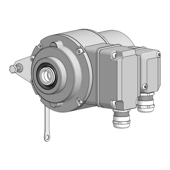
HOG 10 + FSL
Kombination
Inkrementaler Drehgeber mit integriertem
mechanischen Fliehkraftschalter
Combination
Incremental encoder with integrated
mechanical centrifugal switch
Option M: redundant +
Option EMS: LED
Inhaltsverzeichnis

Verwandte Anleitungen für Baumer HOG 10 + FSL


Inhaltszusammenfassung für Baumer HOG 10 + FSL
- Seite 1 Montage- und Betriebsanleitung Mounting and operating instructions Option Heizung Option heating Option M: redundant + Option EMS: LED HOG 10 + FSL Kombination Inkrementaler Drehgeber mit integriertem mechanischen Fliehkraftschalter Combination Incremental encoder with integrated mechanical centrifugal switch...
-
Seite 2: Inhaltsverzeichnis
Inhaltsverzeichnis Inhaltsverzeichnis Allgemeine Hinweise ................................Sicherheitshinweise ................................Vorbereitung .................................... Lieferumfang Gerät ..............................Lieferumfang Klemmenkasten ........................... Zur Montage erforderlich (nicht im Lieferumfang enthalten) ............. Zur Demontage erforderlich (nicht im Lieferumfang enthalten) ............Erforderliches Werkzeug (nicht im Lieferumfang enthalten) ............. Montage ....................................... Schritt 1 .................................. - Seite 3 Table of contents Table of contents General notes ..................................Security indications ................................Preparation ....................................Scope of delivery of the device ......................... Scope of delivery terminal box .......................... Required for mounting (not included in scope of delivery) ..............Required for dismounting (not included in scope of delivery) ............
-
Seite 4: Allgemeine Hinweise
Hinweis zur Gewährleistung eines einwandfreien Betriebes des Gerätes Information Empfehlung für die Gerätehandhabung Die Kombination HOG 10 + FSL ist ein opto-elektronisches Prä zi sionsmessgerät und ein mechanisch wirkendes Schaltgerät, das mit Sorgfalt nur von technisch qualifiziertem Per sonal gehandhabt werden darf. -
Seite 5: General Notes
Informations to ensure correct device operation Information Recommendation for device handling The combination HOG 10 + FSL is an opto electro nic precision measurement device and a mechanically operated switching device which must be handled with care by skilled person- nel only. -
Seite 6: Sicherheitshinweise
Sicherheitshinweise Sicherheitshinweise Verletzungsgefahr durch rotierende Wellen Haare und Kleidungsstücke können von rotierenden Wellen erfasst werden. • Vor allen Arbeiten alle Betriebsspannungen ausschalten und Maschinen stillsetzen. Zerstörungsgefahr durch elektrostatische Aufladung Die elektronischen Bauteile im Gerät sind empfindlich gegen hohe Spannungen. • Steckkontakte und elektronische Komponenten nicht berühren. •... -
Seite 7: Security Indications
Security indications Security indications Risk of injury due to rotating shafts Hair and clothes may become tangled in rotating shafts. • Before all work switch off all voltage supplies and ensure machinery is stationary. Risk of destruction due to electrostatic charge Electronic parts contained in the device are sensitive to high voltages. -
Seite 8: Vorbereitung
Vorbereitung / Preparation Vorbereitung Preparation Lieferumfang Gerät Scope of delivery of the device 2) 3) Gehäuse HOG 10 Housing HOG 10 Gehäuse FSL Housing FSL Einseitig offene Hohlwelle oder Konuswelle Blind hollow shaft or cone shaft mit Schlüsselfläche SW 13 mm with spanner flat 13 mm a/f Spannelement Clamping element... -
Seite 9: Lieferumfang Klemmenkasten
Vorbereitung / Preparation Lieferumfang Klemmenkasten Scope of delivery terminal box Klemmenkastendeckel HOG 10 Terminal box cover HOG 10 Torx-/Schlitzschraube M4x32 mm Torx/slotted screw M4x32 mm Kabelverschraubung M20x1,5 mm Cable gland M20x1.5 mm für Kabel ø5...13 mm for cable ø5...13 mm Anschlussplatine HOG 10, Connecting board HOG 10, siehe Abschnitt 6.1.1.3 und 6.1.4. -
Seite 10: Zur Montage Erforderlich (Nicht Im Lieferumfang Enthalten)
Vorbereitung / Preparation Zur Montage erforderlich Required for mounting (nicht im Lieferumfang enthalten) (not included in scope of delivery) 19b 19c 3x 3x Drehmomentstütze, als Zubehör erhältlich: Torque arm, available as accessory: Bestellnummer Länge L, Version Order number Length L, version 11043628 67...70 mm, Standard 11043628... -
Seite 11: Zur Demontage Erforderlich (Nicht Im Lieferumfang Enthalten)
Vorbereitung / Preparation Zur Demontage erforderlich Required for dismounting (nicht im Lieferumfang enthalten) (not included in scope of delivery) Montage-/Demontageset als Zubehör erhält- Mounting/dismounting kit available as acces- lich, sory, Bestellnummer 11077087, bestehend aus: order number 11077087, including: Gewindestift M6x10 mm, ISO 7436 Setscrew M6x10 mm, ISO 7436 Zylinderschraube M8x45 mm, ISO 4762 Cylinder screw M8x45 mm, ISO 4762... -
Seite 12: Montage
Montage / Mounting Montage Mounting Schritt 1 Step 1 10 mm 10 mm Schritt 2 Step 2 TX 20 Zul. Anzugsmoment Max. tightening torque = 2...3 Nm * Siehe Seite 5 oder 7 See page 5 or 7 MB071.1T2 - 11069399 Baumer_HOG10-FSL-T2_II_DE-EN (18A1) -
Seite 13: Schritt 3 - Einseitig Offene Hohlwelle
Montage / Mounting Schritt 3 - Einseitig offene Hohlwelle Step 3 - Blind hollow shaft Zentrierbohrung Center hole DIN 332-D, M6x16 mm 53 mm (35 mm bei/at ød = 20 mm) ød ød1 16 mm ≥ ø20 mm 52 mm (40...52 mm) 20 mm ≥... -
Seite 14: Schritt 3 - Konuswelle
Montage / Mounting Schritt 3 - Konuswelle Step 3 - Cone shaft Zentrierbohrung Center hole DIN 332-D, M6x16 mm 1:10 Antriebswelle einfetten. Lubricate drive shaft. Die Antriebswelle sollte einen The drive shaft should have as less möglichst kleinen Rundlauffehler runout as possible because this can aufweisen, da dieser zu einem otherwise result in an angle error, see Winkelfehler führen kann, siehe... -
Seite 15: Schritt 4
Montage / Mounting Schritt 4 Step 4 Zul. Anzugsmoment einseitig offene Hohlwelle: Max. tightening torque blind hollow shaft: = 6 Nm Zul. Anzugsmoment Konuswelle: Max. tightening torque cone shaft: 13 mm = 3...4 Nm 5 mm 10 mm 1.6x8 mm * Siehe Seite 7 See page 7 MB071.1T2 - 11069399... -
Seite 16: Schritt 5 - Drehmomentstütze
Montage / Mounting Schritt 5 - Drehmomentstütze Step 5 - Torque arm Die Montage der Drehmomentstütze The torque arm should be mounted sollte spielfrei erfolgen. Ein Spiel von free from clearance. A play of just beispielsweise ±0,03 mm entspricht ±0.03 mm, results in a runout of the einem Rundlauffehler des Gerätes von device of 0.06 mm. -
Seite 17: Hinweis Zur Vermeidung Von Messfehlern
Montage / Mounting Hinweis zur Vermeidung von Messfeh- How to prevent measurement errors lern Für einen einwandfreien Betrieb des To ensure that the device operates cor- Gerätes ist eine korrekte Montage, ins- rectly, it is necessary to mount it accu- besondere auch der Drehmomentstütze, rately as described in section 4.1 to 4.6, notwendig, wie beschrieben in Abschnitt... -
Seite 18: Schritt 6
Montage / Mounting Schritt 6 Step 6 Zul. Anzugsmoment Max. tightening torque = 2...3 Nm TX 20 Ansicht D View D Ansicht D Schieberstellung View D Slider position * Siehe Seite 5 See page 5 MB071.1T2 - 11069399 Baumer_HOG10-FSL-T2_II_DE-EN (18A1) -
Seite 19: Montagehinweis
Montage / Mounting Montagehinweis Mounting instruction Wir empfehlen, das Gerät so zu It is recommended to mount the device montieren, dass der Kabelanschluss with cable connection facing down- keinem direkten Wassereintritt ward and being not exposed to water. ausgesetzt ist. MB071.1T2 - 11069399 Baumer_HOG10-FSL-T2_II_DE-EN (18A1) -
Seite 20: Abmessungen
Abmessungen / Dimensions Abmessungen Dimensions Einseitig offene Hohlwelle Blind hollow shaft (74022, 74029, 74035, 74653) (74022, 74029, 74035, 74653) Positive Drehrichtung Um 90° versetzt gezeichnet Positive rotating direction Drawing 90° rotated 105.5 Option Option M: redundant Zubehör Accessory ød 65.5 51.5 Einseitig offene Hohlwelle und Option Blind hollow shaft and option heating... -
Seite 21: Konuswelle
Abmessungen / Dimensions Konuswelle Cone shaft (74019, 74020, 74636) (74019, 74020, 74636) Um 90° versetzt gezeichnet Positive Drehrichtung Drawing 90° rotated Positive rotating direction 105.5 Option Option M: redundant Zubehör Accessory Konuswelle und Option Heizung Cone shaft and option heating (74648) (74648) Um 90°... -
Seite 22: Elektrischer Anschluss
Elektrischer Anschluss / Electrical connection Elektrischer Anschluss Electrical connection HOG 10 HOG 10 6.1.1 Kabelanschluss 6.1.1 Cable connection 6.1.1.1 Schritt 1 6.1.1.1 Step 1 TX 20 12c * 22 mm 6.1.1.2 Schritt 2 6.1.1.2 Step 2 TX 10 * Siehe Seite 6 See page 6 MB071.1T2 - 11069399 Baumer_HOG10-FSL-T2_II_DE-EN (18A1) - Seite 23 Elektrischer Anschluss / Electrical connection 6.1.1.3 Schritt 3 und 4 6.1.1.3 Step 3 and 4 12c * ø5...13 mm Ansicht X siehe Abschnitt 6.1.4. Kabelschirm View X Cable shield see section 6.1.4. * Siehe Seite 6 oder 7 See page 6 or 7 Zur Gewährleistung der angegebenen To ensure the specified protection of Schutzart sind nur geeignete Kabel-...
- Seite 24 Elektrischer Anschluss / Electrical connection HOG 10 HOG 10 6.1.1 Kabelanschluss 6.1.1 Cable connection 6.1.1.4 Schritt 5 6.1.1.4 Step 5 D-SUB Buchse zum Anschluss an das Gerätegehäuse TX 10 siehe Abschnitt 6.1.1.5. D-SUB connector (female) for connecting to the device housing see section 6.1.1.5.
-
Seite 25: Beschreibung Der Anschlüsse
Elektrischer Anschluss / Electrical connection 6.1.2 Beschreibung der Anschlüsse 6.1.2 Terminal significance Betriebsspannung +UB; + Voltage supply Masseanschluss ; ; GND; 0V Ground Erdungsanschluss (Gehäuse) Earth ground (housing) Ausgangssignal Kanal 1 K1; A; A+ Output signal channel 1 Ausgangssignal Kanal 1 invertiert K1;... -
Seite 26: Klemmenbelegung
Elektrischer Anschluss / Electrical connection HOG 10 HOG 10 6.1.4 Klemmenbelegung 6.1.4 Terminal assignment 6.1.4.1 Standard 6.1.4.1 Standard Max. 1,5 mm Ansicht X Max. AWG 16 Anschlussklemmen, siehe Abschnitt 6.1.1.3. View X Connecting terminal, see section 6.1.1.3. Zwischen besteht keine Verbindung. There is no connection between 6.1.4.2 Option EMS... -
Seite 27: Option Ems (Enhanced Monitoring System): Status Led / Fehlerausgang
Elektrischer Anschluss / Electrical connection 6.1.5 Option EMS (Enhanced Monitoring 6.1.5 Option EMS (Enhanced Monitoring System): Status LED / Fehlerausgang System): Status LED / Error output Rotblinkend Flash light red Signalfolge-, Nullimpuls- oder Impulszahl- Error of signal sequence, zero pulse or fehler pulses (Fehlerausgang = HIGH-LOW-Wechsel) -
Seite 28: Option Heizung: Stromanschluss Für Heizung
Sensorkabel HEK 8 (Zubehör) 6.1.7 Sensor cable HEK 8 (accessory) Es wird empfohlen, das Baumer Hübner Baumer Hübner sensor cable HEK 8 is Sensorkabel HEK 8 zu verwenden oder recommended. As a substitute a shielded ersatzweise ein geschirmtes, paarig ver- twisted pair cable should be used. -
Seite 29: Fsl
Elektrischer Anschluss / Electrical connection 6.2.1 Kabelanschluss 6.2.1 Cable connection 6.2.1.1 Schritt 1 6.2.1.1 Step 1 TX 20 22 mm 6.2.1.2 Schritt 2 6.2.1.2 Step 2 Um 180° wendbarer TX 20 Klemmenkasten. Terminal box, turn by 180°. Zul. Anzugsmoment Ansicht Y Max. -
Seite 30: Klemmenbelegung
Elektrischer Anschluss / Electrical connection 6.2.2 Klemmenbelegung 6.2.2 Terminal assignment Ansicht Y Anschlussklemmen, Schließer siehe Abschnitt 6.2.1.2. Make contact View Y Connecting terminal, see section 6.2.1.2. Ausgangsschaltleistung 1 2 3 Öffner Output switching capacity Break contact ≤6 A / 230 VAC ≤1 A / 125 VDC MB071.1T2 - 11069399 Baumer_HOG10-FSL-T2_II_DE-EN (18A1) -
Seite 31: Demontage
Demontage / Dismounting Demontage Dismounting Schritt 1 Step 1 Elektrische Verbindung trennen. Disconnect electrical connection. TX 10 TX 20 22 mm * Siehe Seite 6 oder 7 See page 6 or 7 MB071.1T2 - 11069399 Baumer_HOG10-FSL-T2_II_DE-EN (18A1) - Seite 32 Demontage / Dismounting Schritt 2 Step 2 Elektrische Verbindung trennen. Disconnect electrical connection. TX 20 22 mm * Siehe Seite 6 oder 7 See page 6 or 7 MB071.1T2 - 11069399 Baumer_HOG10-FSL-T2_II_DE-EN (18A1)
- Seite 33 Demontage / Dismounting Schritt 3 Step 3 10 mm 1.6x8 mm Schritt 4 Step 4 TX 20 Schritt 5 Step 5 13 mm 5 mm * Siehe Seite 5 oder 7 See page 5 or 7 MB071.1T2 - 11069399 Baumer_HOG10-FSL-T2_II_DE-EN (18A1)
- Seite 34 Demontage / Dismounting Schritt 6 Step 6 0.8x4 mm Schritt 7 Step 7 13 mm 6 mm Schritt 8 Step 8 * Siehe Seite 8 See page 8 MB071.1T2 - 11069399 Baumer_HOG10-FSL-T2_II_DE-EN (18A1)
-
Seite 35: Zubehör
Zubehör / Accessories Zubehör Accessories • Drehmomentstütze Größe M6: • Torque arm size M6: Bestellnummer siehe Order number see Abschnitt 3.3 section 3.3 • Montageset für Drehmomentstütze • Mounting kit for torque arm Größe M6 und Erdungsband: size M6 and earthing strap: Bestellnummer 11077197 Order number 11077197 •... -
Seite 36: Technische Daten
Montage / Mounting Technische Daten Technische Daten Technische Daten - elektrisch • Störfestigkeit: EN 61000-6-2 • Störaussendung: EN 61000-6-3 • Zulassung: Technische Daten - elektrisch (Drehgeber) • Betriebsspannung: 9...30 VDC (HTLP, TTL Version R) 5 VDC ±5 % (TTL) •... -
Seite 37: Technische Daten - Mechanisch
Technische Daten - mechanisch • Baugröße (Flansch): ø105 mm • Wellenart: ø16...20 mm (einseitig offene Hohlwelle) ø17 mm (Konuswelle 1:10) • Zulässige Wellenbelastung: ≤450 N axial ≤600 N radial • Schutzart DIN EN 60529: IP66 • Drehzahl (n): ≤1,25 · ns •... -
Seite 38: Technical Data
Technical data Technical data Technical data - electrical ratings • Interference immunity: EN 61000-6-2 • Emitted interference: EN 61000-6-3 • Approval: Technical data - electrical ratings (encoder) • Voltage supply: 9...30 VDC (HTL-P, TTL - version R) 5 VDC ±5 % (TTL) •... -
Seite 39: Technical Data - Mechanical Design
Technical data - mechanical design • Size (flange): ø105 mm • Shaft type: ø16...20 mm (blind hollow shaft) ø17 mm (cone shaft 1:10) • Shaft loading: ≤450 N axial ≤600 N radial • Protection DIN EN 60529: IP66 • Speed (n): ≤1.25 · ns • Range of switching speed (ns): 850...4500 rpm (Δn = 2 rpm/s) (as ordered) • Operating torque: 6 Ncm •... - Seite 40 Baumer Hübner GmbH P.O. Box 12 69 43 · 10609 Berlin, Germany Phone: +49 (0)30/69003-0 · Fax: +49 (0)30/69003-104 info@baumerhuebner.com · www.baumer.com/motion Version: 74019, 74020, 74022, 74035, 74636, 74648, 74649, 74653, 74665 MB071.1T2 - 11069399 Baumer_HOG10-FSL-T2_II_DE-EN (18A1-18.10.2018)