Baumer HOG 11 Montage- Und Betriebsanleitung
Vorschau ausblenden
Andere Handbücher für HOG 11:
- Montage- und betriebsanleitung (32 Seiten) ,
- Montage- und betriebsanleitung (40 Seiten) ,
- Montage- und betriebsanleitung (40 Seiten)

Verwandte Anleitungen für Baumer HOG 11


Inhaltszusammenfassung für Baumer HOG 11
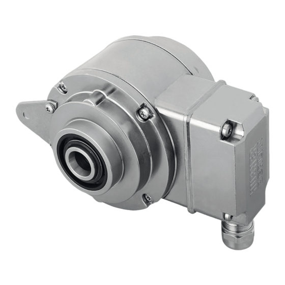
- Seite 1 Montage- und Betriebsanleitung Mounting and operating instructions HOG 11 Inkrementaler Drehgeber mit DNV-Zulassung mit radialem Klemmenkasten Incremental Encoder with DNV approval with radial terminal box...
-
Seite 2: Inhaltsverzeichnis
Montage / Mounting Inhaltsverzeichnis Inhaltsverzeichnis Allgemeine Hinweise ................................Sicherheitshinweise ................................Vorbereitung .................................... Lieferumfang ................................Zur Montage erforderlich (nicht im Lieferumfang enthalten) ............. Zur Demontage erforderlich (nicht im Lieferumfang enthalten) ............Erforderliches Werkzeug (nicht im Lieferumfang enthalten) ............. Montage ....................................... Schritt 1 .................................. - Seite 3 Montage / Mounting Table of contents Table of contents General notes ..................................Security indications ................................Preparation ....................................Scope of delivery ..............................Required for mounting (not included in scope of delivery) ..............Required for dismounting (not included in scope of delivery) ............
-
Seite 4: Allgemeine Hinweise
Information Empfehlung für die Gerätehandhabung Der inkrementale Drehgeber HOG 11 ist ein opto-elektronisches Prä zi sionsmessgerät, das mit Sorgfalt nur von technisch qualifiziertem Per sonal gehandhabt werden darf. Die zu erwartende Lebensdauer des Gerätes hängt von den Kugellagern ab, die mit einer Dauerschmierung ausgestattet sind. -
Seite 5: General Notes
Information Recommendation for device handling The incremental encoder HOG 11 is an opto electro nic precision measurement device which must be handled with care by skilled personnel only. The expected service life of the device depends on the ball bearings, which are equipped with a permanent lubrication. -
Seite 6: Sicherheitshinweise
Sicherheitshinweise Sicherheitshinweise Verletzungsgefahr durch rotierende Wellen Haare und Kleidungsstücke können von rotierenden Wellen erfasst werden. • Vor allen Arbeiten alle Betriebsspannungen ausschalten und Maschinen stillsetzen. Zerstörungsgefahr durch elektrostatische Aufladung Die elektronischen Bauteile im Gerät sind empfindlich gegen hohe Spannungen. • Steckkontakte und elektronische Komponenten nicht berühren. •... -
Seite 7: Security Indications
Security indications Security indications Risk of injury due to rotating shafts Hair and clothes may become tangled in rotating shafts. • Before all work switch off all voltage supplies and ensure machinery is stationary. Risk of destruction due to electrostatic charge Electronic parts contained in the device are sensitive to high voltages. -
Seite 8: Vorbereitung
Vorbereitung / Preparation Vorbereitung Preparation Lieferumfang Scope of delivery Gehäuse Housing Einseitig offene Hohlwelle mit Schlüsselfläche Blind hollow shaft with spanner flat SW 17 mm 17 mm a/f Spannelement Clamping element Erdungsbolzen Earthing bolt Stützblech für Drehmomentstütze Support plate for torque arm Sechskantschraube M6x18 mm, ISO 4017 Hexagon screw M6x18 mm, ISO 4017 Scheibe B6,4, ISO 7090 Washer B6.4, ISO 7090 Selbstsichernde Mutter M6, ISO 10511... -
Seite 9: Zur Montage Erforderlich (Nicht Im Lieferumfang Enthalten)
Vorbereitung / Preparation Zur Montage erforderlich Required for mounting (nicht im Lieferumfang enthalten) (not included in scope of delivery) 3x 3x Torque arm, available as accessory: Drehmomentstütze, als Zubehör erhältlich: Bestellnummer Länge L, Version Order number Length L, version 11043628 67...70 mm, standard 11043628 67...70 mm, Standard 11004078... -
Seite 10: Zur Demontage Erforderlich (Nicht Im Lieferumfang Enthalten)
Vorbereitung / Preparation Zur Demontage erforderlich Required for dismounting (nicht im Lieferumfang enthalten) (not included in scope of delivery) Montage-/Demontageset als Zubehör erhält- Mounting/dismounting kit available as acces- lich: Bestellnr. 11077087, bestehend aus ... sory: Order number 11077087, including ... Gewindestift M6x10 mm, ISO 7436 Setscrew M6x10 mm, ISO 7436 Zylinderschraube M8x45 mm, ISO 4762 Cylinder screw M8x45 mm, ISO 4762 Erforderliches Werkzeug... -
Seite 11: Montage
Montage / Mounting Montage Mounting Schritt 1 Step 1 10 mm 10 mm Schritt 2 Step 2 3 mm * Siehe Seite 5 oder 6 See page 5 or 6 MB072c - 11141929 Baumer_HOG11-DNV_II_DE-EN (18A1) -
Seite 12: Step 3
Montage / Mounting Schritt Step 3 Zentrierbohrung Center hole DIN 332-D, M6x16 mm 53 mm 52 mm (40-52 mm) 16 mm * Siehe Seite 5 See page 5 Antriebswelle einfetten. Lubricate drive shaft. Die Antriebswelle sollte einen The drive shaft should have as less möglichst kleinen Rundlauffehler runout as possible because this can aufweisen, da dieser zu einem... -
Seite 13: Schritt 4
Montage / Mounting Schritt 4 Step 4 Zul. Anzugsmoment: Max. tightening torque: = 6 Nm 17 mm 5 mm 10 mm * Siehe Seite 6 See page 6 MB072c - 11141929 Baumer_HOG11-DNV_II_DE-EN (18A1) -
Seite 14: Schritt 5 - Drehmomentstütze
Montage / Mounting Schritt 5 - Drehmomentstütze Step 5 - Torque arm Die Montage der Drehmomentstütze The torque arm should be mounted sollte spielfrei erfolgen. Ein Spiel von free from clearance. A play of just beispielsweise ±0,03 mm entspricht ±0.03 mm, results in a runout of the einem Rundlauffehler des Gerätes von device of 0.06 mm. -
Seite 15: Hinweis Zur Vermeidung Von Messfehlern
Montage / Mounting Hinweis zur Vermeidung von Messfeh- How to prevent measurement errors lern Für einen einwandfreien Betrieb des To ensure that the device operates cor- Gerätes ist eine korrekte Montage, ins- rectly, it is necessary to mount it accu- besondere auch der Drehmomentstütze, rately as described in section 4.1 to 4.5, notwendig, wie beschrieben in Abschnitt... -
Seite 16: Schritt 6
Montage / Mounting Schritt 6 Step 6 3 mm Zul. Anzugsmoment: Max. tightening torque: = 2...3 Nm * Siehe Seite 5 See page 5 Montagehinweis Mounting instruction Wir empfehlen, das Gerät so zu It is recommended to mount the device montieren, dass der Kabelanschluss with cable connection facing down- keinem direkten Wassereintritt... -
Seite 17: Abmessung
Abmessung - Elektrischer Anschluss / Dimension - Electrical connection Abmessung Dimension (74568) (74568) Positive Drehrichtung Positive rotating direction Um 90° versetzt gezeichnet Drawing 90° rotated Zubehör Accessory Alle Abmessungen in Millimeter (wenn nicht anders angegeben) All dimensions in millimeters (unless otherwise stated) Elektrischer Anschluss Electrical connection Kabelanschluss Cable connection 6.1.1... -
Seite 18: Schritt 2
Elektrischer Anschluss / Electrical connection Kabelanschluss Cable connection 6.1.2 Schritt 2 6.1.2 Step 2 D-SUB Buchse zum Anschluss an das Gerätegehäuse, siehe Abschnitt 6.1.6. TX 10 D-SUB connector (female) for connecting to the device housing, see section 6.1.6. 6.1.3 Schritt 3 6.1.3 Step 3 15 * ø5...13 mm * Siehe Seite 5 oder 6... -
Seite 19: Schritt 4
Elektrischer Anschluss / Electrical connection 6.1.4 Schritt 4 6.1.4 Step 4 Kabelschirm Ansicht X Cable shield siehe Abschnitt 6.3. View X see section 6.3. 6.1.5 Schritt 5 6.1.5 Step 5 TX 10 15 * 22 mm * Siehe Seite 5 See page 5 MB072c - 11141929 Baumer_HOG11-DNV_II_DE-EN (18A1) -
Seite 20: Schritt 6
Elektrischer Anschluss / Electrical connection 6.1.6 Schritt 6 6.1.6 Step 6 Zul. Anzugsmoment: Max. tightening torque: = 2...3 Nm TX 20 Großer, um 180° wendbarer Klemmenkasten. Big terminal box, turn by 180°. Zul. Anzugsmoment: Max. tightening torque: = 2...3 Nm TX 20 * Siehe Seite 5 See page 5 MB072c - 11141929 Baumer_HOG11-DNV_II_DE-EN (18A1) -
Seite 21: Beschreibung Der Anschlüsse
Elektrischer Anschluss / Electrical connection Beschreibung der Anschlüsse 6.2 Terminal significance Betriebsspannung +UB; + Voltage supply Masseanschluss ; ; GND; 0V Ground Erdungsanschluss (Gehäuse) Earth ground (housing) Ausgangssignal Kanal 1 K1; A; A+ Output signal channel 1 Ausgangssignal Kanal 1 invertiert K1; A; A− Output signal channel 1 inverted Ausgangssignal Kanal 2 (90°... -
Seite 22: Ausgangssignale
90° Sensorkabel HEK 8 (Zubehör) Sensor cable HEK 8 (accessory) Es wird empfohlen, das Baumer Hübner Baumer Hübner sensor cable HEK 8 is Sensorkabel HEK 8 zu verwenden oder recommended. As a substitute a shielded ersatzweise ein geschirmtes, paarig ver- twisted pair cable should be used. -
Seite 23: Betrieb Und Wartung
Betrieb und Wartung / Operation and maintenance Betrieb und Wartung Operation and maintenance Austausch der Kohlebürsten Replace of the carbon brushes Bei Erreichen der minimalen Kohlebür- When the minimum carbon brush length stenlänge (L) von 5,3 mm müssen die (L) of 5.3 mm is reached, the carbon Kohlebürsten ausgewechselt werden, brushes must be replaced in order to damit weiterhin ein einwandfreier Betrieb... -
Seite 24: Demontage
Demontage / Dismounting Demontage Dismounting Schritt 1 Step 1 TX 10 TX 20 22 mm 15 * Schritt 2 Step 2 * Siehe Seite 5 oder 6 See page 5 or 6 MB072c - 11141929 Baumer_HOG11-DNV_II_DE-EN (18A1) - Seite 25 Demontage / Dismounting Schritt 3 Step 3 10 mm Schritt 4 Step 4 10 * 3 mm Schritt 5 Step 5 17 mm 5 mm * Siehe Seite 5 oder 6 See page 5 or 6 MB072c - 11141929 Baumer_HOG11-DNV_II_DE-EN (18A1)
- Seite 26 Demontage / Dismounting Schritt 6 Step 6 0.8x4 mm Schritt 7 Step 7 17 mm 6 mm Schritt 8 Step 8 * Siehe Seite 7 See page 7 MB072c - 11141929 Baumer_HOG11-DNV_II_DE-EN (18A1)
-
Seite 27: Zubehör
Zubehör / Accessories Zubehör Accessories • Drehmomentstütze Größe M6: • Torque arm size M6: Bestellnummer siehe Order number see Abschnitt 3.2 section 3.2 • Montageset für Drehmoment- • Mounting kit for torque arm stütze Größe M6: size M6: Bestellnummer 11071904 Order number 11071904 •... -
Seite 28: Technische Daten
Montage / Mounting Technische Daten Technische Daten 10.1 Technische Daten - elektrisch • Betriebsspannung: 9...30 VDC (HTL-P, TTL - Version R) 5 VDC ±5 % (TTL) • Betriebsstrom ohne Last: ≤100 mA • Impulse pro Umdrehung: 300...2500 (je nach Bestellung) •... -
Seite 29: Technical Data
Technical data Technical data 10.1 Technical data - electrical ratings • Voltage supply: 9...30 VDC (HTL-P, TTL - version R) 5 VDC ±5 % (TTL) • Consumption w/o load: ≤100 mA • Pulses per revolution: 300...2500 (as ordered) • Phase shift: 90° ±20° •... -
Seite 30: Eu-Konformitätserklärung
Signature/nom/fonction Baumer_Geber_mit_Erdungsbürste_oder_Heizung_DE-EN-FR_CoC_81201634.docm/kwe Baumer Hübner GmbH P.O. Box 126943 ∙ D-10609 Berlin ∙ Max-Dohrn-Str. 2+4 ∙ D-10589 Berlin Phone +49 (0)30 69003-0 ∙ Fax +49 (0)30 69003-104 ∙ info@baumerhuebner.com ∙ www.baumer.com Sitz der Gesellschaft / Registered Office: Berlin, Germany ∙ Geschäftsführer / Managing Director: Dr. Oliver Vietze, Dr. Johann Pohany Handelsregister / Commercial Registry: AG Charlottenburg HRB 96409 ∙... -
Seite 31: Dnv-Zertifikat
DNV-Zertifikat / DNV certificate DNV-Zertifikat DNV certificate MB072c - 11141929 Baumer_HOG11-DNV_II_DE-EN (18A1) - Seite 32 Baumer Hübner GmbH P.O. Box 12 69 43 · 10609 Berlin, Germany Phone: +49 (0)30/69003-0 · Fax: +49 (0)30/69003-104 info@baumerhuebner.com · www.baumer.com/motion Version: 74568 MB072c - 11141929 Baumer_HOG11-DNV_II_DE-EN (18A1-20.08.2018)