Pilz PNOZ XV1P Betriebsanleitung
Vorschau ausblenden
Andere Handbücher für PNOZ XV1P:
- Bedienungsanleitung (29 Seiten) ,
- Betriebsanleitung (16 Seiten)
Inhaltsverzeichnis
Werbung
Quicklinks
20 596-06
PNOZ XV1P
Sicherheitsbestimmungen
• Das Gerät darf nur von Personen installiert
und in Betrieb genommen werden, die mit
dieser Betriebsanleitung und den gel-
tenden Vorschriften über Arbeitssicherheit
und Unfallverhütung vertraut sind.
Beachten Sie die VDE- sowie die örtlichen
Vorschriften, insbesondere hinsichtlich
Schutzmaßnahmen.
• Beim Transport, der Lagerung und im
Betrieb die Bedingungen nach EN 60068-
2-6 einhalten (s. technische Daten).
• Durch Öffnen des Gehäuses oder eigen-
mächtige Umbauten erlischt jegliche Ge-
währleistung.
• Montieren Sie das Gerät in einen Schalt-
schrank; Staub und Feuchtigkeit können
sonst zu Beeinträchtigungen der Funktio-
nen führen.
• Sorgen Sie an allen Ausgangskontakten
bei kapazitiven und induktiven Lasten für
eine ausreichende Schutzbeschaltung.
Bestimmungsgemäße Verwendung
Das Sicherheitsschaltgerät dient dem
sicherheitsgerichteten Unterbrechen eines
Sicherheitsstromkreises. Das Sicherheits-
schaltgerät erfüllt Forderungen der
EN 60947-5-1, EN 60204-1 und VDE 0113-1
und darf eingesetzt werden in Anwendungen
mit
• Not-Halt-Tastern
• Schutztüren
• Lichtschranken
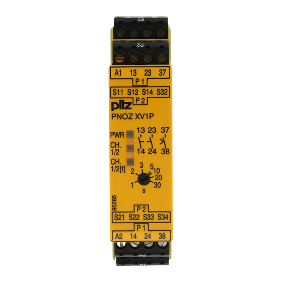
Gerätebeschreibung
Das Sicherheitschaltgerät ist in einem
S-99-Gehäuse untergebracht. Es steht eine
Ausführung für den Betrieb mit 24 V
Gleichspannung zur Verfügung.
Merkmale:
• Relaisausgänge, unverzögert:
2 Sicherheitskontakte (S), zwangsgeführt
• Relaisausgang, rückfallverzögert:
1 Sicherheitskontakt (S), zwangsgeführt,
mit einstellbarer Rückfallverzögerung
• Statusanzeigen für Versorgungsspannung
und Schaltzustand aller Ausgangskanäle
• Anschluss für Not-Halt-Taster, Sicher-
heitsendschalter oder Schutztürschalter
und für externen Starttaster
• redundante Ausgangsschaltung
• ein- oder zweikanaliger Betrieb
• Rückführkreis zur Überwachung externer
Schütze
Das Schaltgerät erfüllt folgende Sicherheits-
anforderungen:
• Die Sicherheitseinrichtung bleibt auch in
folgenden Fällen wirksam:
- Spannungsausfall
- Ausfall eines Bauteils
- Spulendefekt
- Leiterbruch
- Erdschluss
• Bei jedem Ein-Aus-Zyklus Überprüfung, ob
die Ausgangsrelais des Sicherheitsgerätes
richtig öffnen und schließen.
Safety Regulations
• The unit may only be installed and
operated by personnel who are familiar
with both these instructions and the current
regulations for safety at work and accident
prevention. Follow VDE and local
regulations especially as regards
preventative measures.
• Transport, storage and operating con-
ditions should all conform to EN 60068-
2-6.
• Any guarantee is void following opening of
the housing or unauthorised modifications.
• The unit should be panel mounted,
otherwise dampness or dust could lead to
function impairment.
• Adequate protection must be provided on
all output contacts especially with
capacitive and inductive loads.
Authorised Applications
The safety relay provides a safety-related
interruption of a safety circuit. The safety
relay meets the requirements of EN 60947-5-
1, EN 60204-1 and VDE 0113-1 and may be
used in applications with
• E-STOP pushbuttons
• Safety gates
• Light barriers
Description
The Safety Relay is enclosed in a S-99
housing. The version available is for 24 V DC
operation only.
Features:
• Relay Outputs, instantaneous
2 safety contacts (n/o), positive-guided
• Relay output, delay-on de-energised:
1 safety contact (n/o), positive-guided with
adjustable delay-on de-energisation
• LED for Operating Voltageand for
switching positions of all output channnels
• Connection for Safety limit switches,
Emergency stop buttons or safety gate
switches and for external reset buttons
• Output circuit is redundant
• Single or two channel operation
• Feedback control loop for monitoring
external contactors/relays
The relay complies with the following safety
requirements:
• The Emergency Stop Relay prevents
machine operation in the following cases:
- Power supply failure
- Component failure
- Coil defect in a relay
- Cable break
- Earth fault
• The correct opening and closing of the
safety function output relays is tested
automatically in each on-off cycle.
- 1 -
Conseils préliminaires
• La mise en oeuvre de l'appareil doit être
effectuée par une personne spécialisée en
installations électriques, en tenant compte
des prescriptions des différentes normes
applicables (NF, EN, VDE...) notamment
au niveau des risques encourus en cas de
défaillance de l'équipement électrique.
• Respecter les exigences de la norme
EN 60068-2-6 lors du transport, du
stockage et de l'utilisation de l'appareil.
• L'ouverture de l'appareil ou sa modification
annule automatiquement la garantie.
• L'appareil doit être monté dans une ar-
moire; l'humidité et la poussière pouvant
entraîner des aléas de fonctionnement.
• Vérifiez que le pouvoir de coupure des
contacts de sortie est suffisant en cas de
circuits capacitifs ou inductifs.
Domaines d'utilisation
Le bloc logique de sécurité sert à interrompre
en toute sécurité un circuit de sécurité. Le
bloc logique de sécurité satisfait aux
exigences des normes EN 60947-5-1,
EN 60204-1 et VDE 0113-1 et peut être
utilisé dans des applications avec des
• poussoirs d'arrêt d'urgence
• protecteurs mobiles
• barrières immatérielles
Description de l'appareil
Inséré dans un boîtier S-99, le bloc logique
de sécurité PNOZ XV1P est disponible
uniquement en 24 V DC
Caractéristiques :
• Contacts de sortie instantanés :
2 contacts à fermeture de sécurité (F).
• Contact de sortie temporisé :
1 contact à fermeture de sécurité (F),
temporisé à la retombée avec tempori-
sation réglable
• LED d'indication présence tension et LEDs
de visualisation des canaux de sortie
• Bornes de raccordement pour poussoirs
AU, fins de course de sécurité ou
interrupteurs de position et poussoir de
validation externe.
• Sorties redondantes.
• Commande par un ou deux canaux.
• Boucle de retour pour l'auto-contrôle de
contacteurs externes.
Le relais répond aux exigences suivantes :
• La sécurité est garantie, même dans les
cas suivants :
- Défaillance tension
- Défaillance d'un composant
- Défaillance bobine
- Défaut soudure
- Défaut de masse
• Vérification à chaque mise en route du bon
fonctionnement des relais internes.
Werbung
Inhaltsverzeichnis

Verwandte Anleitungen für Pilz PNOZ XV1P


Inhaltszusammenfassung für Pilz PNOZ XV1P
- Seite 1 Inséré dans un boîtier S-99, le bloc logique S-99-Gehäuse untergebracht. Es steht eine housing. The version available is for 24 V DC de sécurité PNOZ XV1P est disponible Ausführung für den Betrieb mit 24 V operation only. uniquement en 24 V DC Gleichspannung zur Verfügung.
-
Seite 2: Funktionsbeschreibung
Description du fonctionnement Das Schaltgerät PNOZ XV1P dient dem The relay PNOZ XV1P provides a safety- Le relais PNOZ XV1P assure de façon sure, sicherheitsgerichteten Unterbrechen eines oriented interruption of a safety circuit. When l’ouverture d’un circuit de sécurité. A la mise Sicherheitsstromkreises. -
Seite 3: Montage
• As the function for detecting shorts across • Da die Funktion Querschlusserkennung sur site est possible de la façon suivante : the inputs is not failsafe, it is tested by Pilz nicht einfehlersicher ist, wird sie von Pilz 1. Appareil en fonction (contacts de sortie during the final control check. - Seite 4 Les figures 2 à 10 représentent les différents In Fig. 2 ... Fig. 10 sind Anschlussbeispiele für for Emergency Stop wiring with automatic câblages possibles du PNOZ XV1P à savoir : Not-Halt-Beschaltung mit automatischem und and monitored reset. Safety gate controls as poussoir AU avec réarmement automatique...
-
Seite 5: Fehler - Störungen
Fig. 10: wie Fig. 9 mit überwachtem Start/ Fig. 9: Anschlussbeispiel für externe Fig. 8: Lichtschrankensteuerung, zwei- connection for contactors/relays and kanalig, Querschlusserkennung durch BWS, Schütze, einkanalig, automatischer Start/ monitored reset/comme Fig. 9 avec überwachter Start/Dual-channel light curtain Connection example for external contactors/ surveillance du poussoir de validation control, short circuit detection via ESPE, relays, single-channel, automatic reset/... - Seite 6 Technische Daten Technical Data Caractéristiques techniques Elektrische Daten Electrical data Données électriques Versorgungsspannung U Supply Voltage U Tension d’alimentation U DC: 24 V Spannungstoleranz Voltage Tolerance Plage de la tension d’alimentation -15 ... +10 % Leistungsaufnahme bei U Power consumption at U Consommation pour U 3,5 W DC: 20 %...
- Seite 7 Rückfallverzögerung Delay-on De-Energisation Temps de retombée bei Not-Halt at E-STOP en cas d'arrêt d'urgence typ.: 15 ms, max.: 30 ms bei Netzausfall with power failure en cas de coupure d'alimentation typ.: 100 ms, max.: 150 ms Wiederbereitschaftszeit bei max. Recovery time at max. switching Temps de remise en service en cas de Schaltfrequenz 1/s frequency 1/s...
-
Seite 8: Abmessungen In Mm /Dimensions In Mm /Dimensions En Mm
Konventioneller thermischer Strom bei gleichzeitiger Belastung mehrerer Kontakte/Conventional thermal current while loading several contacts/Courant thermique conventionnel en cas de charge sur plusieurs contacts (AC1, DC1) Anzahl der Kontakte/number of contacts/nombre des contacts (A) pro Kontakt /per contact /par contact Um ein Versagen der Geräte zu verhindern, To prevent failure of the unit, all output Prévoir un dispositif d’extinction d’arc sur les an allen Ausgangskontakten für eine aus-... -
Seite 9: Steckbare Klemmen Abziehen
Die vollständige EG-Konformitätserklärung The complete EC Declaration of Conformity Vous trouverez la déclaration de conformité finden Sie im Internet unter www.pilz.com is available on the Internet at www.pilz.com CE complète sur notre site internet Bevollmächtigter: Norbert Fröhlich, Authorised representative: Norbert Fröhlich, www.pilz.com... - Seite 10 0224 2360180, Fax: 0224 2360184, E-Mail: pilz.tr@pilz.de Pilz Automation Safety L.P ., 734 354-0272, Fax: 734 354-3355, E-Mail: info@pilzusa.com www.pilz.com ✆ Pilz GmbH & Co. KG, Sichere Automation, Felix-Wankel-Straße 2, 73760 Ostfildern, Deutschland, +49 711 3409-0, Fax: +49 711 3409-133, E-Mail: pilz.gmbh@pilz.de - 10 -...
- Seite 11 20 596-06 PNOZ XV1P Prescripciones de seguridad Norme di sicurezza Veiligheidsvoorschriften • El dispositivo tiene que ser instalado y • Il dispositivo può venire installato e messo • Het apparaat mag uitsluitend worden puesto en funcionamiento exclusivamente in funzione solo da persone che conosco- geïnstalleerd en in bedrijf genomen door...
- Seite 12 Descrizione del funzionamento Descripción del funcionamiento Functiebeschrijving Il modulo PNOZ XV1P serve per interrom- El dispositivo PNOZ XV1P sirve para interrum- Het relais PNOZ XV1P dient om een pir por razones de seguridad un circuito de pere per motivi di sicurezza un circuito veiligheidscircuit veilig te onderbreken.
-
Seite 13: Montaje
Il controllo dell’apparecchio Een controle na de installatie van het ap- da por Pilz en el control final. Una verifi- dopo l’installazione può essere eseguito paraat is als volgt mogelijk: cación después de la instalación del dis-... - Seite 14 Activar de nuevo: Riattivazione: Opnieuw activeren: • Cierre el circuito de entrada o accione el • Chiudere il circuito di ingresso o agire • Sluit het ingangscircuit of bedien de pulsador de rearme recién después de nuovamente sul pulsante di start startknop weer pas nadat de transcurrido el tiempo de retardo + soltanto dopo il periodo di ritardo +...
- Seite 15 Fig. 8: Control de barrera fotoeléctrica, Fig. 9: Ejemplo de conexión para contactores Fig. 10: como fig. 9 con rearme supervisado/ bicanal, detección de corto circuito externos, monocanal, rearme automático/ come fig. 9 con start controllato/zoals fig. 9 transversal mediante BWS, rearme Esempio di collegamento per relè...
- Seite 16 Datos técnicos Dati tecnici Technische gegevens Datos eléctricos Dati elettrici Elektrische gegevens Tensión de alimentación U Tensione di alimentazione U Voedingsspanning U DC. 24 V Tolerancia de tensión Tolleranza di tensione Spanningstolerantie -15 ... +10 % Consumo de energía con U Potenza assorbita con U Opgenomen vermogen bij U 3,5 W...
- Seite 17 Tiempo de recuperación con la Tempo di ripristino per frequenza di Resettijd bij max. schakelfrequentie frecuencia máxima de 1/s commutazione max. 1/s tras parada de emergencia dopo arresto di emergenza na noodstop 50 ms + tv tras interrupción del suministro dopo perdita di alimentazione na uitvallen spanning eléctrico...
- Seite 18 Corriente térmica convencional de los contactos de seguridad/Corrente termica convenzionale dei contatti di sicurezza/Conventionele thermische stroom van de veiligheidscontacten (AC1, DC1) Número de contactos/Numero dei contatti/Aantal contacten (A) por contacto /per contatto /per contact Para evitar una falla de los dispositivos, se Per impedire l’avaria dei dispositivi, assicu- Om een falen van de relais te verhinderen, moet debe procurar una suficiente extinción de...
- Seite 19 CE è disponibile in Internet Gevolmachtige: Norbert Fröhlich, Internet www.pilz.com all’indirizzo www.pilz.com Pilz GmbH & Co. KG, Felix-Wankel-Str. 2, Apoderado: Norbert Fröhlich, Mandatario: Norbert Fröhlich, 73760 Ostfildern, Duitsland Pilz GmbH & Co. KG, Felix-Wankel-Str. 2, Pilz GmbH &...
- Seite 20 0224 2360180, Fax: 0224 2360184, E-Mail: pilz.tr@pilz.de Pilz Automation Safety L.P ., 734 354-0272, Fax: 734 354-3355, E-Mail: info@pilzusa.com www.pilz.com ✆ Pilz GmbH & Co. KG, Sichere Automation, Felix-Wankel-Straße 2, 73760 Ostfildern, Deutschland, +49 711 3409-0, Fax: +49 711 3409-133, E-Mail: pilz.gmbh@pilz.de - 20 -...