Inhaltsverzeichnis
Werbung
Quicklinks
20 690-04
PNOZ XV2.1
Sicherheitsbestimmungen
• Das Gerät darf nur von Personen installiert
und in Betrieb genommen werden, die mit
dieser Betriebsanleitung und den gel-
tenden Vorschriften über Arbeitssicherheit
und Unfallverhütung vertraut sind.
Beachten Sie die VDE- sowie die örtlichen
Vorschriften, insbesondere hinsichtlich
Schutzmaßnahmen.
• Beim Transport, der Lagerung und im
Betrieb die Bedingungen nach EN 60068-
2-6 einhalten (s. technische Daten).
• Durch Öffnen des Gehäuses oder eigen-
mächtige Umbauten erlischt jegliche Ge-
währleistung.
• Montieren Sie das Gerät in einen Schalt-
schrank; Staub und Feuchtigkeit können
sonst zu Beeinträchtigungen der Funktio-
nen führen.
• Sorgen Sie an allen Ausgangskontakten
bei kapazitiven und induktiven Lasten für
eine ausreichende Schutzbeschaltung.
Bestimmungsgemäße Verwendung
Das Sicherheitsschaltgerät dient dem
sicherheitsgerichteten Unterbrechen eines
Sicherheitsstromkreises. Das Sicherheits-
schaltgerät erfüllt Forderungen der
EN 60947-5-1, EN 60204-1 und VDE 0113-1
und darf eingesetzt werden in Anwendungen
mit
• NOT-AUS-Tastern
• Schutztüren
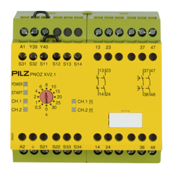
Gerätebeschreibung
Das NOT-AUS-Schaltgerät ist in einem
P-97-Gehäuse untergebracht. Es kann mit
24 ... 240 V AC/DC betrieben werden.
Merkmale:
• Relaisausgänge, unverzögert:
2 Sicherheitskontakte (S), zwangsgeführt
• Relaisausgänge, rückfallverzögert:
2 Sicherheitskontakte (S), zwangsgeführt,
mit einstellbarer oder fester Rückfallver-
zögerung
• Statusanzeigen für Versorgungsspannung
und Schaltzustand aller Ausgangsrelais
• Anschluss für NOT-AUS-Taster, Sicher-
heitsendschalter oder Schutztürschalter
und für externen Starttaster
• redundante Ausgangsschaltung
• ein- oder zweikanaliger Betrieb
• Rückführkreis zur Überwachung externer
Schütze
Das Schaltgerät erfüllt folgende Sicherheits-
anforderungen:
• Die Sicherheitseinrichtung bleibt auch in
folgenden Fällen wirksam:
Spannungsausfall, Ausfall eines Bauteil,
Spulendefekt, Leiterbruch, Erdschluss
• Bei jedem Ein-Aus-Zyklus Überprüfung,
ob die Ausgangsrelais des Sicherheits-
gerätes richtig öffnen und schließen
Safety Regulations
• The unit may only be installed and
operated by personnel who are familiar
with both these instructions and the current
regulations for safety at work and accident
prevention. Follow VDE and local
regulations especially as regards
preventative measures.
• Transport, storage and operating conditions
should all conform to EN 60068-2-6.
• Any guarantee is void following opening of
the housing or unauthorised modifications.
• The unit should be panel mounted,
otherwise dampness or dust could lead to
function impairment.
• Adequate protection must be provided on
all output contacts especially with
capacitive and inductive loads.
Authorised Applications
The safety relay provides a safety-related
interruption of a safety circuit. The safety
relay meets the requirements of EN 60947-5-
1, EN 60204-1 and VDE 0113-1 and may be
used in applications with
• E-STOP pushbuttons
• Safety gates
Description
The Emergency Stop Relay is enclosed in a
P-97 housing. The unit can be operated with
with 24 ... 240 V AC/DC.
Features:
• Relay Outputs, instantaneous
2 safety contacts (n/o), positive-guided
• Relay outputs, delay-on de-energised:
2 safety contacts (n/o), positive-guided
with adjustable or fixed delay-on de-
energisation
• LED for Operating Voltage and LED's for
switching positions of all output relays
• Connection for Safety limit switches,
Emergency stop buttons or safety gate
switches and for external reset buttons
• Output circuit is redundant
• Single or two channel operation
• Feedback control loop for monitoring
external contactors/relays
The relay complies with the following safety
requirements:
• The Emergency Stop Relay prevents
machine operation in the following cases:
power supply failure, component failure,
coil defect in a relay, cable break, earth
fault
• The correct opening and closing of the
Safety Gate limit switches and the safety
function output relays is tested
automatically in each on-off cycle
- 1 -
Conseils préliminaires
• La mise en oeuvre de l'appareil doit être
effectuée par une personne spécialisée en
installations électriques, en tenant compte
des prescriptions des différentes normes
applicables (NF, EN, VDE...) notamment
au niveau des risques encourus en cas de
défaillance de l'équipement électrique.
• Respecter les exigences de la norme
EN 60068-2-6 lors du transport, du
stockage et de l'utilisation de l'appareil.
• L'ouverture de l'appareil ou sa modification
annule automatiquement la garantie.
• L'appareil doit être monté dans une ar-
moire; l'humidité et la poussière pouvant
entraîner des aléas de fonctionnement.
• Vérifiez que le pouvoir de coupure des
contacts de sortie est suffisant en cas de
circuits capacitifs ou inductifs.
Domaines d'utilisation
Le bloc logique de sécurité sert à interrompre
en toute sécurité un circuit de sécurité. Le
bloc logique de sécurité satisfait aux
exigences des normes EN 60947-5-1,
EN 60204-1 et VDE 0113-1 et peut être
utilisé dans des applications avec des
• poussoirs d'arrêt d'urgence
• protecteurs mobiles
Description de l'appareil
Inséré dans un boîtier P-97, le bloc logique
de sécurité PNOZ X2P peut être alimenté en
24 ... 240 V AC/DC.
Caractéristiques :
• Contacts de sortie instantanés :
2 contacts à fermeture de sécurité (F).
• Contacts de sortie temporisés :
2 contacts à fermeture de sécurité (F),
temporisés à la retombée avec tempori-
sation réglable ou fixe
• LED d'indication présence tension et LEDs
de visualisation des relais internes
• Bornes de raccordement pour poussoirs
AU, fins de course de sécurité ou
interrupteurs de position et poussoir de
validation externe.
• Sorties redondantes.
• Commande par un ou deux canaux.
• Boucle de retour pour l'auto-contrôle de
contacteurs externes.
Le relais répond aux exigences suivantes :
• La sécurité est garantie, même dans les
cas suivants :
Défaillance tension, défaillance d'un
omposant, défaillance bobine, défaut
soudure, défaut de masse
• Vérification à chaque mise en route du bon
fonctionnement des relais internes
Werbung
Inhaltsverzeichnis

Verwandte Anleitungen für Pilz PNOZ XV2.1


Inhaltszusammenfassung für Pilz PNOZ XV2.1
- Seite 1 20 690-04 PNOZ XV2.1 Sicherheitsbestimmungen Safety Regulations Conseils préliminaires • Das Gerät darf nur von Personen installiert • The unit may only be installed and • La mise en oeuvre de l’appareil doit être und in Betrieb genommen werden, die mit operated by personnel who are familiar effectuée par une personne spécialisée en...
- Seite 2 Description du fonctionnement Das Schaltgerät PNOZ XV2.1 dient dem The relay PNOZ XV2.1 provides a safety- Le relais PNOZ XV2.1 assure de façon sure, sicherheitsgerichteten Unterbrechen eines oriented interruption of a safety circuit. When l’ouverture d’un circuit de sécurité. A la mise Sicherheitsstromkreises.
-
Seite 3: Montage
• As the function for detecting shorts across (Circuits d’entrée) nicht einfehlersicher ist, wird sie von Pilz the inputs is not failsafe, it is tested by Pilz /km = résistivité de câblage/km während der Endkontrolle geprüft. Eine during the final control check. However, a •... - Seite 4 Les figures 2 à 10 représentent les différents für NOT-AUS-Beschaltung mit automati- for Emergency Stop wiring with automatic câblages possibles du PNOZ XV2.1 à savoir: schem und überwachtem Start, Schutztür- and monitored reset. Safety gate controls as poussoir AU avec réarmement automatique...
-
Seite 5: Fehler - Störungen
Fig. 5: Schutztürsteuerung einkanalig, Fig. 6: Schutztürsteuerung zweinkanalig, Fig. 7: Schutztürsteuerung zweikanalig, überwachter Start/Single-channel safety gate überwachter Start/Two-channel safety gate automatischer Start/Two channel safety gate control, monitored reset/Surveillance de control, monitored reset/Surveillance de control, automatic reset/Surveillance de protecteur, commande par 1 canal, protecteur, commande par 2 canaux, protecteur, commande par 2 canaux, surveillance du poussoir de validation... - Seite 6 Technische Daten/Technical Data/Caractéristiques techniques Versorgungsspannung U /Operating Voltage/Tension d’alimentation 24 - 240 V AC/DC Spannungstoleranz/Voltage Tolerance/Plage de la tension d’alimentation -15 ... +10 % Leistungsaufnahme bei U /Power Consumption/Consommation DC: 5,0 W AC: 8,5 VA Frequenzbereich/Frequency Range/Fréquence 50 - 60 Hz Spannung und Strom an/Voltage, Current at //Tension et courant du Eingangskreis/Input circuit/circuit d’entrée = 24 V DC: 35 mA...
- Seite 7 Luft- und Kriechstrecken nach/Airgap Creepage to/Cheminement et claquage d'après EN 60947-1 Verschmutzungsgrad/Pollution degree/Niveau d'encrassement Bemessungsisolationsspannung/Rated insulation voltage/Tension assignée d’isolement 250 V Bemessungsstoßspannungsfestigkeit/Rated impulse withstand voltage/Tension assignée de tenue aux chocs 4 kV Betriebstemperatur/Operating Temperature/Température d’utilisation -10 - 55 °C Lagertemperatur/Storage Temperature/Température de stockage -40 - 85 °C Schutzart/Protection/Indice de protection Einbauraum (z.
- Seite 8 0224 2360180, Fax: 0224 2360184, E-Mail: pilz.tr@pilz.de Pilz Automation Safety L.P ., 734 354-0272, Fax: 734 354-3355, E-Mail: info@pilzusa.com www.pilz.com ✆ Pilz GmbH & Co. KG, Sichere Automation, Felix-Wankel-Straße 2, 73760 Ostfildern, Deutschland, +49 711 3409-0, Fax: +49 711 3409-133, E-Mail: pilz.gmbh@pilz.de - 8 -...
- Seite 9 20 690-04 PNOZ XV2.1 Normas de seguridad Norme di sicurezza Veiligheidsvoorschriften • El dispositivo debe ser instalado y puesto en • L’apparecchio deve essere installato e • Het apparaat mag uitsluitend worden funcionamiento solo por personas, que ten- messo in funzione solo da persone a geïnstalleerd en in bedrijf genomen door...
-
Seite 10: Descrizione Del Funzionamento
Características funcionales Descrizione del funzionamento Functiebeschrijving El relé PNOZ XV2.1 sirve para una interrup- L’apparecchio elettrico PNOZ XV2.1 serve Het relais PNOZ XV2.1 dient om een ción por motivos de seguridad, de un circuito per interrompere in modo sicuro un circuito veiligheidscircuit met zekerheid te de seguridad. -
Seite 11: Montaje
• Poiché la funzione di rilevamento corto- door Pilz tijdens de eindcontrole getest. fallo, es proba-da por Pilz en el control circuito non è protetta dagli errori, essa Een controle na de installatie van het ap- final. - Seite 12 • Circuito de entrada: • Circuito di entrata • Ingangscircuit: - Monocanal: Puentear S21-S22 y S31- - Monocanale: ponticellare S21-S22 e - Eenkanalig: S21-S22 en S31-S32 S32. Conectar el contacto S31-S32. Collegare il contatto di riposo verbinden. Verbreekcontact van normalmente cerrado del interruptor de dell’elemento di scatto a S11 e S12.
- Seite 13 S11 S31 S11 S31 Fig. 2: Circuito de entrada monocanal, Fig. 3: Circuito de entrada monocanal, Fig. 4: Circuito de entrada bicanal, rearme automát. rearme/Circuito di entrata rearme supervisado/Circuito di entrata supervisado/Circuito di entrata bicanale, monocanale, start automat./Eenkanalig monocanale, start controllato/Eenkanalig start controllato/Tweekanalig ingangscircuit, ingangscircuit, automatische start ingangscircuit, bewaakte start...
- Seite 14 Datos técnicos/Dati tecnici/Technische gegevens Tensión de funcionamiento U /Tensione di alimentazione U /Voedingsspanning U 24 - 240 V AC/DC Tolerancia de tensión/Tolleranza di tensione/Spanningstolerantie -15 ... +10 % Consumo de energía con U /Potenza assorbita con U /Opgenomen vermogen bij U DC: 5,0 W AC: 8,5 VA Rango de frequencia/Gamma di frequenza/Frequentiebereik...
- Seite 15 Distancias de fuga y dispersión superficial según/Intraferri d'aria e vie di dispersione secondo/ Lucht- en kruipwegen volgens EN 60947-1 Grado de suciedad/Grado di contaminazione/Vervuilingsgraad Tensión de aislamiento de dimensionado/Tensione nominale di isolamento/ Nominale isolatiespanning 250 V Resistencia tensión transitoria de dimensionado/Tensione di tenuta agli urti/Nominale stootspanningbestendigheid 4 kV Temperatura ambiente/Temperatura ambiete/Omgevingstemperatuur...
- Seite 16 0224 2360180, Fax: 0224 2360184, E-Mail: pilz.tr@pilz.de Pilz Automation Safety L.P ., 734 354-0272, Fax: 734 354-3355, E-Mail: info@pilzusa.com www.pilz.com ✆ Pilz GmbH & Co. KG, Sichere Automation, Felix-Wankel-Straße 2, 73760 Ostfildern, Deutschland, +49 711 3409-0, Fax: +49 711 3409-133, E-Mail: pilz.gmbh@pilz.de - 16 -...