Pilz PNOZ XV2P Betriebsanleitung
Vorschau ausblenden
Andere Handbücher für PNOZ XV2P:
- Bedienungsanleitung (35 Seiten) ,
- Bedienungsanleitung (37 Seiten)
Inhaltsverzeichnis
Werbung
Quicklinks
20 095-03
PNOZ XV2P
Sicherheitsbestimmungen
• Das Gerät darf nur von Personen installiert
und in Betrieb genommen werden, die mit
dieser Betriebsanleitung und den gel-
tenden Vorschriften über Arbeitssicherheit
und Unfallverhütung vertraut sind.
Beachten Sie die VDE- sowie die örtlichen
Vorschriften, insbesondere hinsichtlich
Schutzmaßnahmen.
• Beim Transport, der Lagerung und im
Betrieb die Bedingungen nach EN 60068-
2-6 einhalten (s. technische Daten).
• Durch Öffnen des Gehäuses oder eigen-
mächtige Umbauten erlischt jegliche Ge-
währleistung.
• Montieren Sie das Gerät in einen Schalt-
schrank; Staub und Feuchtigkeit können
sonst zu Beeinträchtigungen der Funktio-
nen führen.
• Sorgen Sie an allen Ausgangskontakten
bei kapazitiven und induktiven Lasten für
eine ausreichende Schutzbeschaltung.
Bestimmungsgemäße Verwendung
Das Sicherheitsschaltgerät erfüllt Forderun-
gen der EN 60947-5-1, EN 60204-1 und
VDE 0113-1 und darf eingesetzt werden in
Anwendungen mit
• NOT-AUS-Tastern
• Schutztüren
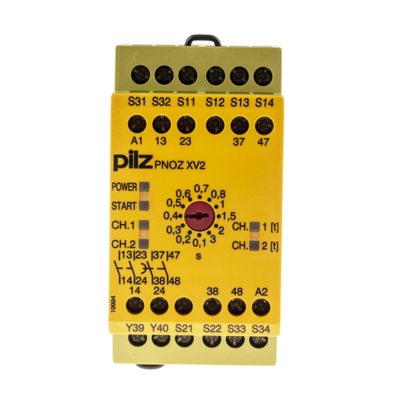
Gerätebeschreibung
Das NOT-AUS-Schaltgerät ist in einem
P-99-Gehäuse untergebracht. Es steht eine
Ausführung für den Betrieb mit 24 V
Gleichspannung zur Verfügung.
Merkmale:
• Relaisausgänge, unverzögert:
2 Sicherheitskontakte (S), zwangsgeführt
• Relaisausgänge, rückfallverzögert:
2 Sicherheitskontakte (S), zwangsgeführt,
mit einstellbarer oder fester Rückfallver-
zögerung (geräteabhängig)
• Statusanzeigen für Versorgungsspannung,
Schaltzustand aller Ausgangsrelais und
Startkreis
• Anschluss für NOT-AUS-Taster, Sicher-
heitsendschalter oder Schutztürschalter
und für externen Starttaster
• redundante Ausgangsschaltung
• ein- oder zweikanaliger Betrieb
• Rückführkreis zur Überwachung externer
Schütze
Das Schaltgerät erfüllt folgende Sicherheits-
anforderungen:
• Die Sicherheitseinrichtung bleibt auch in
folgenden Fällen wirksam:
- Spannungsausfall
- Ausfall eines Bauteils
- Spulendefekt
- Leiterbruch
- Erdschluss
• Bei jedem Ein-Aus-Zyklus Überprüfung, ob
die Ausgangsrelais des Sicherheitsgerätes
richtig öffnen und schließen
Safety Regulations
• The unit may only be installed and
operated by personnel who are familiar
with both these instructions and the current
regulations for safety at work and accident
prevention. Follow VDE and local
regulations especially as regards
preventative measures.
• Transport, storage and operating con-
ditions should all conform to EN 60068-
2-6.
• Any guarantee is void following opening of
the housing or unauthorised modifications.
• The unit should be panel mounted,
otherwise dampness or dust could lead to
function impairment.
• Adequate protection must be provided on
all output contacts especially with
capacitive and inductive loads.
Authorised Applications
The safety relay meets the requirements of
EN 60947-5-1, EN 60204-1 and
VDE 0113-1 and may be used in applications
with
• E-STOP pushbuttons
• Safety gates
Description
The Emergency Stop Relay is enclosed in a
P-99 housing. The version available is for
24 V DC operation only.
Features:
• Relay Outputs, instantaneous
2 safety contacts (n/o), positive-guided
• Relay outputs, delay-on de-energised:
2 safety contacts (n/o), positive-guided
with adjustable or fixed delay-on de-
energisation (dependent on unit)
• LED for Operating Voltage, LED's for
switching positions of all output relays and
reset circuit
• Connection for Safety limit switches,
Emergency stop buttons or safety gate
switches and for external reset buttons
• Output circuit is redundant
• Single or two channel operation
• Feedback control loop for monitoring
external contactors/relays
The relay complies with the following safety
requirements:
• The Emergency Stop Relay prevents
machine operation in the following cases:
- Power supply failure
- Component failure
- Coil defect in a relay
- Cable break
- Earth fault
• The correct opening and closing of the
Safety Gate limit switches and the safety
function output relays is tested
automatically in each on-off cycle
- 1 -
Conseils préliminaires
• La mise en oeuvre de l'appareil doit être
effectuée par une personne spécialisée en
installations électriques, en tenant compte
des prescriptions des différentes normes
applicables (NF, EN, VDE...) notamment
au niveau des risques encourus en cas de
défaillance de l'équipement électrique.
• Respecter les exigences de la norme
EN 60068-2-6 lors du transport, du
stockage et de l'utilisation de l'appareil.
• L'ouverture de l'appareil ou sa modification
annule automatiquement la garantie.
• L'appareil doit être monté dans une ar-
moire; l'humidité et la poussière pouvant
entraîner des aléas de fonctionnement.
• Vérifiez que le pouvoir de coupure des
contacts de sortie est suffisant en cas de
circuits capacitifs ou inductifs.
Domaines d'utilisation
Le bloc logique de sécurité satisfait aux
exigences des normes EN 60947-5-1,
EN 60204-1 et VDE 0113-1 et peut être
utilisé dans des applications avec des:
• poussoirs d'arrêt d'urgence
• protecteurs mobiles
Description de l'appareil
Inséré dans un boîtier P-99, le bloc logique
de sécurité PNOZ XV2P est disponible
uniquement en 24 V DC
Caractéristiques :
• Contacts de sortie instantanés :
2 contacts à fermeture de sécurité (F).
• Contacts de sortie temporisés :
2 contacts à fermeture de sécurité (F),
temporisés à la retombée avec tempori-
sation réglable ou fixe (suivant appareil)
• LED d'indication présence tension, LEDs
de visualisation des relais internes et du
circuit de réarmement
• Bornes de raccordement pour poussoirs
AU, fins de course de sécurité ou
interrupteurs de position et poussoir de
validation externe.
• Sorties redondantes.
• Commande par un ou deux canaux.
• Boucle de retour pour l'auto-contrôle de
contacteurs externes.
Le relais répond aux exigences suivantes :
• La sécurité est garantie, même dans les
cas suivants :
- Défaillance tension
- Défaillance d'un composant
- Défaillance bobine
- Défaut soudure
- Défaut de masse
• Vérification à chaque mise en route du bon
fonctionnement des relais internes
Werbung
Inhaltsverzeichnis

Verwandte Anleitungen für Pilz PNOZ XV2P


Inhaltszusammenfassung für Pilz PNOZ XV2P
- Seite 1 Inséré dans un boîtier P-99, le bloc logique P-99-Gehäuse untergebracht. Es steht eine P-99 housing. The version available is for de sécurité PNOZ XV2P est disponible Ausführung für den Betrieb mit 24 V 24 V DC operation only. uniquement en 24 V DC Gleichspannung zur Verfügung.
-
Seite 2: Funktionsbeschreibung
Description du fonctionnement Das Schaltgerät PNOZ XV2P dient dem The relay PNOZ XV2P provides a safety- Le relais PNOZ XV2P assure de façon sure, sicherheitsgerichteten Unterbrechen eines oriented interruption of a safety circuit. When l’ouverture d’un circuit de sécurité. A la mise Sicherheitsstromkreises. -
Seite 3: Montage
• Kontaktvervielfachung und -verstärkung • Augmentation du nombre de contacts ou • Increase in the number of available durch Anschluss von externen Schützen du pouvoir de coupure par l’utilisation de contacts by connection of external contacteurs externes. contactors/relays. Montage Montage Installation Das Sicherheitsschaltgerät muss in einen The safety relay must be panel mounted... - Seite 4 Les figures 2 à 10 représentent les différents In Fig. 2 ... Fig. 10 are connection examples für NOT-AUS-Beschaltung mit automati- câblages possibles du PNOZ XV2P à savoir : for Emergency Stop wiring with automatic schem und überwachtem Start, Schutztür- poussoir AU avec réarmement automatique...
-
Seite 5: Fehler - Störungen
Fig. 8: Öffnerkontakt für Reset der Fig. 9: Anschlussbeispiel für externe Fig. 10: wie Fig. 9 mit überwachtem Start/ Verzögerungszeit/N/C contact for reseting Schütze, einkanalig, automatischer Start/ connection for contactors/relays and the Delay-on De-energisation/Contact à Connection example for external contactors/ monitored reset/comme Fig. -
Seite 6: Technische Daten/Technical Data/Caractéristiques Techniques
Technische Daten/Technical Data/Caractéristiques techniques Versorgungsspannung U /Operating Voltage/Tension d’alimentation 24 V DC Spannungstoleranz/Voltage Tolerance/Plage de la tension d’alimentation -15 % / +10 % Leistungsaufnahme bei U /Power Consumption/Consommation 4,5 W Restwelligkeit/Residual Ripple/Ondulation résiduelle DC: 160 % Spannung und Strom an/Voltage, Current at //Tension et courant du Eingangskreis/Input circuit/circuit d’entrée 24 V DC/35 mA Startkreis/reset circuit/circuit de réarmement... - Seite 7 Umgebungstemperatur/Operating Temperature/Température d’utilisation -10 ... + 55 °C Lagertemperatur/Storage Temperature/Température de stockage -40 ... +85 °C Schutzart/Protection/Indice de protection Einbauraum (z. B. Schaltschrank)/Mounting (eg. panel)/Lieu d'implantation (ex. armoire) IP54 Gehäuse/Housing/Boîtier IP40 Klemmenbereich/Terminals/Bornes IP20 Gehäusematerial/housing material/matériau du boîtier Gehäuse/Housing/Boîtier PPO UL 94 V0 Front/front panel/face avant ABS UL 94 V0 Max.Querschnitt des Außenleiters (Schraubklemmen)/Max.
-
Seite 8: Steckbare Klemmen Abziehen
0224 2360180, Fax: 0224 2360184, E-Mail: pilz.tr@pilz.de Pilz Automation Safety L.P ., 734 354-0272, Fax: 734 354-3355, E-Mail: info@pilzusa.com www.pilz.com ✆ Pilz GmbH & Co. KG, Sichere Automation, Felix-Wankel-Straße 2, 73760 Ostfildern, Deutschland, +49 711 3409-0, Fax: +49 711 3409-133, E-Mail: pilz.gmbh@pilz.de - 8 -... - Seite 9 20 095-03 PNOZ XV2P Veiligheidsvoorschriften Normas de seguridad Norme di sicurezza • Het apparaat mag uitsluitend worden • Il dispositivo deve essere installato e • El dispositivo debe ser instalado y puesto geïnstalleerd en in bedrijf genomen door messo in funzione solo da persone a en funcionamiento sólo por personas que...
-
Seite 10: Descripción Funcional
Descrizione del funzionamento Descripción funcional Functiebeschrijving Il dispositivo elettrico PNOZ XV2P serve per El dispositivo PNOZ XV2P sirve para la inter- Het relais PNOZ XV2P dient om een interrompere in modo sicuro un circuito rupción por motivos de seguridad de un cir- veiligheidscircuit veilig te onderbreken. -
Seite 11: Montaje
activa tan pronto como se cierra el circuito • Start automatico: il dispositivo è attivo non is pas actief, als vóór het sluiten van het de entrada. appena il circuito di ingresso è chiuso. ingangscircuit het startcircuit (S33-S34) • Rearme manual con supervisión: El dispo- •... - Seite 12 (cerrados). Se iluminan los indicadores de LED di stato per «CH.1», «CH.2», «CH.1(t)» De veiligheidscontacten zijn geactiveerd estado para “CH.1”, “CH. 2”, “CH.1(t)” y e «CH.2(t)» sono accesi. Il dispositivo è (gesloten). De status-LED’s voor "CH.1", “CH.2(t)“. El dispositivo está listo para pronto per il funzionamento.
- Seite 13 Fig. 8: Contacto normalmente cerrado para Fig. 9: Ejemplo de conexión para contactores Fig. 10: como la Fig. 9 con rearme el reset del tiempo de retardo/Contatto NC externos, monocanal, rearme automático/ supervisado/come fig. 9 con start per il ripristino del tempo di ritardo/ Esempio di collegamento per relè...
- Seite 14 Datos técnicos/Dati tecnici/Technische gegevens Tensión de alimentación U /Tensione di alimentazione/Voedingsspanning 24 V DC Tolerancia U /Tolleranza U /Tolerantie U -15% / +10 % Consumo de energía con U /Potenza assorbita a U /Opgenomen vermogen bij U DC: 4,5 W Ondulación residual/Ondulazione residua/Rimpelspanning DC: 160 % Tensión e intensidad en/Tensione e corrente su/Spanning en stroom op...
- Seite 15 Temperatura ambiental/Temperatura ambiente/Omgevingstemperatuur -10 ... + 55 °C Temperatura de almacenaje/Temperatura di immagazzinamento/Opslagtemperatuur -40 ... +85 °C Grado de protección/Grado di protezione/Beschermingsgraad Lugar de montaje (ej. armario de distribución)/Vano di montaggio (per es. armadio elettrico)/ inbouwruimte (b. v. schakelkast) IP54 Carcasa/Custodia/Behuizing IP40 Bornes/Zona morsetti/Klemmenstrook...
- Seite 16 0224 2360180, Fax: 0224 2360184, E-Mail: pilz.tr@pilz.de Pilz Automation Safety L.P ., 734 354-0272, Fax: 734 354-3355, E-Mail: info@pilzusa.com www.pilz.com ✆ Pilz GmbH & Co. KG, Sichere Automation, Felix-Wankel-Straße 2, 73760 Ostfildern, Deutschland, +49 711 3409-0, Fax: +49 711 3409-133, E-Mail: pilz.gmbh@pilz.de - 16 -...