Baumer HOG 165 + DSL Montage- Und Betriebsanleitung

Verwandte Anleitungen für Baumer HOG 165 + DSL


Inhaltszusammenfassung für Baumer HOG 165 + DSL
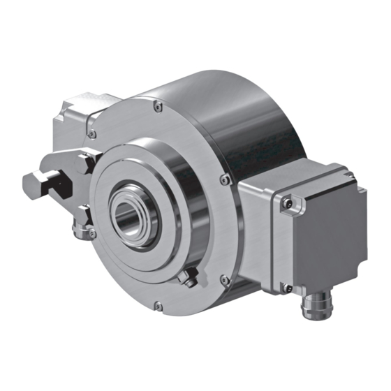
- Seite 1 Montage- und Betriebsanleitung Mounting and operating instructions HOG 165 + DSL Kombination Inkrementaler Drehgeber mit integriertem programmierbaren, digitalen Drehzahlschalter Combination Incremental encoder with integrated programmable, digital speed switch...
-
Seite 2: Inhaltsverzeichnis
Inhaltsverzeichnis Inhaltsverzeichnis Allgemeine Hinweise ................................Betrieb in explosionsgefährdeten Bereichen ....................Sicherheitshinweise ................................Vorbereitung .................................... Lieferumfang ................................Zur Montage erforderlich (nicht im Lieferumfang enthalten) ............. Zur Demontage erforderlich (nicht im Lieferumfang enthalten) ............. Erforderliches Werkzeug (nicht im Lieferumfang enthalten) ............Montage ..................................... - Seite 3 Table of contents Table of contents General notes ..................................Operation in potentially explosive environments ................... Security indications ................................Preparation ....................................Scope of delivery ..............................Required for mounting (not included in scope of delivery) ..............Required for dismounting (not included in scope of delivery) ............
-
Seite 4: Allgemeine Hinweise
Hinweis zur Gewährleistung eines einwandfreien Betriebes des Gerätes Information Empfehlung für die Gerätehandhabung Die Kombination HOG 165 + DSL ist ein opto-elektronisches Prä zi sionsmessgerät und ein programmierbares, digital wirkendes Schaltgerät, das mit Sorgfalt nur von technisch qualifi- ziertem Per sonal gehandhabt werden darf. -
Seite 5: General Notes
Informations to ensure correct device operation Information Recommendation for device handling The combination HOG 165 + DSL is an opto electro nic precision measurement device and a programmable, digital operated switching device which must be handled with care by skilled personnel only. -
Seite 6: Betrieb In Explosionsgefährdeten Bereichen
Betrieb in explosionsgefährdeten Bereichen Betrieb in explosionsgefährdeten Bereichen Das Gerät entspricht der Richtlinie 2014/34/EU für explosionsgefährdete Bereiche. Der Einsatz ist gemäß den Gerätekategorien 3 G (Ex-Atmosphäre Gas) und 3 D (Ex-Atmo- sphäre Staub) zulässig. Das Relaismodul DS 93 R, als Zubehör erhältlich, siehe Abschnitt 7.2.5, darf nicht in explosions- gefährdeten Bereichen eingesetzt werden. -
Seite 7: Operation In Potentially Explosive Environments
Operation in potentially explosive environments Operation in potentially explosive environments The device complies with the directive 2014/34/EU for potentionally explosive atmospheres. It can be used in accordance with equipment categories 3 G (explosive gas atmosphere) and 3 D (explosive dust atmosphere). The relay modul DS 93 R, available as accessory, see section 7.2.5, must not be used in poten- tionally explosive atmospheres. -
Seite 8: Sicherheitshinweise
Sicherheitshinweise Sicherheitshinweise Verletzungsgefahr durch rotierende Wellen Haare und Kleidungsstücke können von rotierenden Wellen erfasst werden. • Vor allen Arbeiten alle Betriebsspannungen ausschalten und Maschinen stillsetzen. Zerstörungsgefahr durch elektrostatische Aufladung Die elektronischen Bauteile im Gerät sind empfindlich gegen hohe Spannungen. • Steckkontakte und elektronische Komponenten nicht berühren. •... -
Seite 9: Security Indications
Security indications Security indications Risk of injury due to rotating shafts Hair and clothes may become tangled in rotating shafts. • Before all work switch off all voltage supplies and ensure machinery is stationary. Risk of destruction due to electrostatic charge Electronic parts contained in the device are sensitive to high voltages. -
Seite 10: Vorbereitung
Vorbereitung / Preparation Vorbereitung Preparation Lieferumfang Scope of delivery Gehäuse Housing Gewindebuchse mit Insert nut with Schlüsselfläche SW 46 mm spanner flat 46 mm a/f Abdeckhaube Cover Zylinderschraube M4x8 mm, ISO 4762 Cylinder screw M4x8 mm, ISO 4762 Klemmenkastendeckel HOG 165 Terminal box cover HOG 165 Torx-/Schlitzschraube M4x32 mm Torx/slotted screw M4x32 mm Kabelverschraubung M20x1,5 mm... - Seite 11 Vorbereitung / Preparation Lieferumfang Scope of delivery 19 18 15 16 13 20 19 18 Einseitig offene Hohlwelle Blind hollow shaft Spannelement Clamping element Stütze für Drehmomentstütze Brace for torque arm Sechskantschraube ø12 mm auf M10x35 mm Hexagon screw ø12 mm to M10x35 mm Scheibe A13, ISO 7090 Washer A13, ISO 7090 Selbstsichernde Mutter M10, ISO 10511...
-
Seite 12: Zur Montage Erforderlich (Nicht Im Lieferumfang Enthalten)
Vorbereitung / Preparation Zur Montage erforderlich Required for mounting (nicht im Lieferumfang enthalten) (not included in scope of delivery) 3x 3x Drehmomentstütze, als Zubehör erhältlich: Torque arm, available as accessory: Bestellnummer Länge L, Version Order number Length L, version 11054922 155 (-10/+15) mm, Standard 11054922 155 (-10/+15) mm, standard 11054921... -
Seite 13: Zur Demontage Erforderlich (Nicht Im Lieferumfang Enthalten)
Vorbereitung / Preparation Zur Demontage erforderlich Required for dismounting (nicht im Lieferumfang enthalten) (not included in scope of delivery) Gewindestift M6x10 mm, ISO 7436 Setscrew M6x10 mm, ISO 7436 Abdrückschraube M8x45 mm, ISO 4762 Jack screw M8x45 mm, ISO 4762 Erforderliches Werkzeug Required tools (nicht im Lieferumfang enthalten) (not included in scope of delivery) -
Seite 14: Montage
Montage / Mounting Montage Mounting Schritt 1 Step 1 17 mm 19 mm 13 15 Schritt 2 Step 2 3 mm * Siehe Seite 7, 8 oder 9 See page 7, 8 or 9 MB104.3T1 - 11113957 Baumer_HOG165-DSL-T1_II_DE-EN (18A1) -
Seite 15: Schritt 3
Montage / Mounting Schritt 3 Step 3 Zul. Anzugsmoment Max. tightening torque = 6 Nm 12 * 5 mm 1.6x8 mm 18 mm Ansicht A View A Alle Abmessungen in Millimeter (wenn nicht anders angegeben) * Siehe Seite 8 oder 9 All dimensions in millimeters (unless otherwise stated) See page 8 or 9 Antriebswelle einfetten. -
Seite 16: Schritt 4 - Drehmomentstütze
Montage / Mounting Schritt 4 - Drehmomentstütze Step 4 - Torque arm Die Montage der Drehmomentstütze The torque arm should be mounted sollte spielfrei erfolgen. Ein Spiel von free from clearance. A play of just beispielsweise ±0,03 mm entspricht ±0.03 mm, results in a runout of the einem Rundlauffehler des Gerätes von device of 0.06 mm. -
Seite 17: Hinweis Zur Vermeidung Von Messfehlern
Montage / Mounting Hinweis zur Vermeidung von Messfeh- How to prevent measurement errors lern Für einen einwandfreien Betrieb des To ensure that the device operates cor- Gerätes ist eine korrekte Montage, ins- rectly, it is necessary to mount it accu- besondere auch der Drehmomentstütze, rately as described in section 5.1 to 5.4, notwendig, wie beschrieben in Abschnitt... -
Seite 18: Schritt 5
Montage / Mounting Schritt 5 Step 5 3 mm Zul. Anzugsmoment Max. tightening torque = 2...3 Nm * Siehe Seite 7 See page 7 Montagehinweis Mounting instruction Wir empfehlen, das Gerät so zu It is recommended to mount the device montieren, dass der Kabelanschluss with cable connection facing down- keinem direkten Wassereintritt... -
Seite 19: Abmessung
Abmessung / Dimension Abmessung Dimension (74435, 74442) (74435, 74442) Um 90° versetzt gezeichnet Drawing 90° rotated ød ø20 ø25 Zubehör Accessory Um 90° versetzt gezeichnet Positive Drehrichtung Drawing 90° rotated Positive rotating direction Alle Abmessungen in Millimeter (wenn nicht anders angegeben) All dimensions in millimeters (unless otherwise stated) MB104.3T1 - 11113957 Baumer_HOG165-DSL-T1_II_DE-EN (18A1) -
Seite 20: Elektrischer Anschluss
Elektrischer Anschluss / Electrical connection Elektrischer Anschluss Electrical connection HOG 165 HOG 165 7.1.1 Kabelanschluss 7.1.1 Cable connection 7.1.1.1 Schritt 1 7.1.1.1 Step 1 TX 20 22 mm 7.1.1.2 Schritt 2 7.1.1.2 Step 2 TX 10 * Siehe Seite 7 See page 7 MB104.3T1 - 11113957 Baumer_HOG165-DSL-T1_II_DE-EN (18A1) - Seite 21 Elektrischer Anschluss / Electrical connection 7.1.1.3 Schritt 3 bis 5 7.1.1.3 Step 3 up to 5 Ansicht X siehe Abschnitt 7.1.4. Kabelschirm View X Cable shield see section 7.1.4. ø5...13 mm TX 10 D-SUB Buchse zum Anschluss an das Gerätegehäuse, siehe Abschnitt 7.1.1.4. D-SUB connector (female) for connecting to 22 mm...
- Seite 22 Elektrischer Anschluss / Electrical connection HOG 165 HOG 165 7.1.1 Kabelanschluss 7.1.1 Cable connection 7.1.1.4 Schritt 6 7.1.1.4 Step 6 Zul. Anzugsmoment Max. tightening torque = 2...3 Nm TX 20 Großer, um 180° wendbarer Klemmenkasten. Big terminal box, turn by 180°. * Siehe Seite 7 See page 7 Vor der Montage des Klemmenkasten- Check that the seal of the terminal box...
-
Seite 23: Beschreibung Der Anschlüsse
Elektrischer Anschluss / Electrical connection 7.1.2 Beschreibung der Anschlüsse 7.1.2 Terminal significance Betriebsspannung +UB; + Voltage supply Masseanschluss ; ; GND; 0 V Ground Erdungsanschluss (Gehäuse) Earth ground (housing) Ausgangssignal Kanal 1 K1; A; A+ Output signal channel 1 Ausgangssignal Kanal 1 invertiert K1;... -
Seite 24: Dsl.r Für Den Betrieb Mit Einem Externen Relaismodul Ds 93 R (Zubehör)
Elektrischer Anschluss / Electrical connection DSL.R für den Betrieb mit einem exter- DSL.R suitable for operation with the nen Relaismodul DS 93 R (Zubehör) external relay modul DS 93 R (acces- sory) 7.2.1 Kabelanschluss 7.2.1 Cable connection 7.2.1.1 Schritt 1 7.2.1.1 Step 1 TX 20 21 * 22 mm... - Seite 25 Elektrischer Anschluss / Electrical connection 7.2.1.2 Schritt 2 7.2.1.2 Step 2 TX 20 Kabelschirm Zul. Anzugsmoment Cable shield Max. tightening torque = 2...3 Nm 21 * 22 mm ø5...13 mm Ansicht Y siehe Abschnitt 7.2.2. View Y see section 7.2.2. Um 180° wendbarer Klemmenkasten. Terminal box, turn by 180°.
-
Seite 26: Klemmenbelegung
Elektrischer Anschluss / Electrical connection 7.2.2 Klemmenbelegung 7.2.2 Terminal assignment Drei Schaltausgänge, welche drehzahlab- 3 switching outputs that can be switched hängig geschaltet werden. Bei Stillstand according to the speed. If the device is at des Gerätes oder Drehzahl n kleiner standstill or the rotational speed n is less Schaltdrehzahl ns ist der jeweilige Schalt- than the switching speed ns then the cor- ausgang high, bei n ≥... -
Seite 27: Blockschaltbild
Elektrischer Anschluss / Electrical connection 7.2.3 Blockschaltbild 7.2.3 Block diagramm Kombination/Combination 15...30 VDC High = 12 V, Low = 0 V HOG 165 DSL.R 0 V (GND) RS 485 für/for PC/Laptop A, B 0 V (GND) 7.2.4 Ausgangsschaltverhalten 7.2.4 Switching characteristics 12 VDC 1,2,3 0 V (GND) -ns off... -
Seite 28: Relaismodul (Zubehör)
Elektrischer Anschluss / Electrical connection 7.2.5 DS 93 R 7.2.5 DS 93 R Relaismodul (Zubehör) relay modul (accessory) 7.2.5.1 Klemmenbelegung 7.2.5.1 Terminal assignment 3 Kontroll-LED‘s Höhe = 55 mm Kunststoffgehäuse für 3 control LEDs Tragschienenmontage (EN 50022) IP 20 Height = 55 mm 3 Relais/relays Plastic housing for ≤6 A / 250 VAC... -
Seite 29: Dsl.e, Mit Drei Internen Elektronischen Relais
Elektrischer Anschluss / Electrical connection DSL.E, mit drei internen elektro- DSL.E with three internal electronic nischen Relais relays 7.3.1 Kabelanschluss 7.3.1 Cable connection 7.3.1.1 Schritt 1 7.3.1.1 Step 1 TX 20 21 * 22 mm * Siehe Seite 8 See page 8 MB104.3T1 - 11113957 Baumer_HOG165-DSL-T1_II_DE-EN (18A1) - Seite 30 Elektrischer Anschluss / Electrical connection 7.3.1.2 Schritt 2 7.3.1.2 Step 2 TX 20 Kabelschirm Zul. Anzugsmoment Cable shield Max. tightening torque = 2...3 Nm 21 * 22 mm ø5...13 mm Ansicht Z siehe Abschnitt 7.3.2. View Z see section 7.3.2. Um 180° wendbarer Klemmenkasten. Terminal box, turn by 180°.
-
Seite 31: Klemmenbelegung
Elektrischer Anschluss / Electrical connection 7.3.2 Klemmenbelegung 7.3.2 Terminal assignment Integrierte Stromfluss-Überwachung bei Integrated current monitoring for each jedem Relais: Messung, ob bei geschlos- relay: This checks whether, when the relay senem Relais ein Strom (mind. 5 mA) is closed, a current of at least 5 mA flows durch den geschalteten Stromkreis fließt. through the switched circuit. -
Seite 32: Blockschaltbild
Sensor cable HEK 8 (accessory for 165) HOG 165) Es wird empfohlen, das Baumer Hübner Baumer Hübner sensor cable HEK 8 is Sensorkabel HEK 8 zu verwenden oder recommended. As a substitute a shielded ersatzweise ein geschirmtes, paarig ver- twisted pair cable should be used. -
Seite 33: Demontage
Demontage / Dismounting Demontage Dismounting Schritt 1 Step 1 Elektrische Verbindung trennen. Disconnect electrical connection. TX 10 TX 20 22 mm * Siehe Seite 7 oder 9 See page 7 or 9 MB104.3T1 - 11113957 Baumer_HOG165-DSL-T1_II_DE-EN (18A1) - Seite 34 Demontage / Dismounting Schritt 2 Step 2 Elektrische Verbindung trennen. Disconnect electrical connection. TX 20 21 * 22 mm * Siehe Seite 8 oder 9 See page 8 or 9 MB104.3T1 - 11113957 Baumer_HOG165-DSL-T1_II_DE-EN (18A1)
- Seite 35 Demontage / Dismounting Schritt 3 Step 3 3 mm 17 * 1.6x8 mm 18 mm Schritt 4 Step 4 5 mm * Siehe Seite 7, 8 oder 9 See page 7, 8 or 9 MB104.3T1 - 11113957 Baumer_HOG165-DSL-T1_II_DE-EN (18A1)
- Seite 36 Demontage / Dismounting Schritt 5 Step 5 0.8x4 mm Schritt 6 Step 6 6 mm * Siehe Seite 10 See page 10 MB104.3T1 - 11113957 Baumer_HOG165-DSL-T1_II_DE-EN (18A1)
- Seite 37 Demontage / Dismounting Schritt 7 Step 7 MB104.3T1 - 11113957 Baumer_HOG165-DSL-T1_II_DE-EN (18A1)
-
Seite 38: Technische Daten
Technische Daten Technische Daten Technische Daten - elektrisch • Betriebsstrom ohne Last: ≤200 mA HOG 165 + DSL.E • Betriebsspannung: 9...30 VDC HOG 165 + DSL.R • Betriebsspannung: 15...30 VDC Technische Daten - elektrisch (Drehgeber) • Impulse pro Umdrehung: 512...4096 (je nach Bestellung) •... -
Seite 39: Technische Daten - Mechanisch
Technische Daten - mechanisch • Baugröße (Flansch): ø165 mm • Wellenart: ø20 mm (durchgehende Hohlwelle) ø25 mm (durchgehende Hohlwelle) (je nach Bestellung) • Zulässige Wellenbelastung: ≤500 N axial ≤650 N radial • Schutzart DIN EN 60529: IP67 • Drehzahl (n): ≤6000 U/min (mechanisch) •... -
Seite 40: Technical Data
Technical data Technical data Technical data - electrical ratings • Consumption w/o load: ≤200 mA HOG 165 + DSL.E • Voltage supply: 9...30 VDC HOG 165 + DSL.R • Voltage supply: 15...30 VDC Technical data - electrical ratings (encoder) • Pulses per revolution: 512...4096 (as ordered) -
Seite 41: Technical Data - Mechanical Design
Technical data - mechanical design • Size (flange): ø165 mm • Shaft type: ø20 mm (through hollow shaft) ø25 mm (through hollow shaft) (as ordered) • Admitted shaft load: ≤500 N axial ≤650 N radial • Protection DIN EN 60529: IP67 • Speed (n): ≤6000 rpm • Range of switching speed (ns ): Pulses = 512: ±16...6000 rpm... -
Seite 42: Zubehör
Zubehör / Accessories Zubehör Accessories 10.1 Für die Kombination 10.1 For the combination • Drehmomentstütze Größe M12: • Torque arm size M12: Bestellnummer siehe Order number see Abschnitt 4.2 section 4.2 • Montageset für Drehmoment- • Mounting kit for torque arm stütze Größe M12 und Erdungs- size M12 and earthing strap: band: Bestellnummer 11069336 Order number 11069336... -
Seite 43: Eu-Konformitätserklärung
Signature/nom/fonction Baumer_POGxDSL_HOGxDSL_DE-EN-FR_CoC_81201223.docm/kwe Baumer Hübner GmbH P.O. Box 126943 ∙ D-10609 Berlin ∙ Max-Dohrn-Str. 2+4 ∙ D-10589 Berlin Phone +49 (0)30 69003-0 ∙ Fax +49 (0)30 69003-104 ∙ info@baumerhuebner.com ∙ www.baumer.com Sitz der Gesellschaft / Registered Office: Berlin, Germany ∙ Geschäftsführer / Managing Director: Dr. Oliver Vietze, Dr. Johann Pohany Handelsregister / Commercial Registry: AG Charlottenburg HRB 96409 ∙... - Seite 44 Baumer Hübner GmbH P.O. Box 12 69 43 · 10609 Berlin, Germany Phone: +49 (0)30/69003-0 · Fax: +49 (0)30/69003-104 info@baumerhuebner.com · www.baumer.com/motion Version: 74435, 74442 MB104.3T1 - 11113957 Baumer_HOG165-DSL-T1_II_DE-EN (18A1-12.10.2018)