Inhaltsverzeichnis
Werbung
Verfügbare Sprachen
Verfügbare Sprachen
Istruzioni per installazione, uso e manutenzione
Montage und Bedienungs Anleitung
Manuel d'entretien
Installation, use and maintenance instructions
Bruciatori di gasolio
I
Öl-Gebläsebrenner
D
Brûleurs fioul
F
Oil burners
GB
Funzionamento monostadio
Einstufig
Fonctionnement à 1 allure
One stage operation
CODICE
CODE
3737150
3737151
3737250
3737251
3737350
3737351
MODELLO - MODELL
MODELE - MODEL
BG1
BG1E
Con /mit /avec/with FLAME MONITOR
BG2
BG2E
Con /mit /avec/with FLAME MONITOR
BG3
BG3E
Con /mit /avec/with FLAME MONITOR
TIPO - TYP
TYPE
371 T1
371 T1
372 T1
372 T1
373 T1
373 T1
2902318 (0)
Werbung
Kapitel
Inhaltsverzeichnis

Verwandte Anleitungen für Riello Burners Gulliver BLU BG1 Type 371 T1


Inhaltszusammenfassung für Riello Burners Gulliver BLU BG1 Type 371 T1
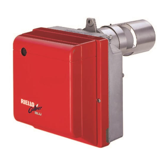
- Seite 1 Istruzioni per installazione, uso e manutenzione Montage und Bedienungs Anleitung Manuel d’entretien Installation, use and maintenance instructions Bruciatori di gasolio Öl-Gebläsebrenner Brûleurs fioul Oil burners Funzionamento monostadio Einstufig Fonctionnement à 1 allure One stage operation CODICE MODELLO - MODELL TIPO - TYP CODE MODELE - MODEL TYPE...
- Seite 2 Dichiarazione del produttore secondo la normativa 1. BImSchV, 1996 R.B.L. RIELLO BRUCIATORI LEGNAGO S.p.A. dichiara che i seguenti prodotti rispettano i valori limite degli NOx imposti dalla normativa 1. BImSchV, 1996, § 7 (2): Herstellerbescheinigung gemäß 1. BImSchV, 1996 R.B.L. RIELLO BRUCIATORI LEGNAGO S.p.A. bestätigt, daß folgende Produkte, die von der 1.
-
Seite 3: Inhaltsverzeichnis
INDICE DESCRIZIONE DEL BRUCIATORE ..1 FUNZIONAMENTO ....6 1.1 Materiale a corredo ....1 4.1 Regolazione della combustione. -
Seite 4: Dati Tecnici
2. DATI TECNICI 2.1 DATI TECNICI TIPO 371 T1 372 T1 373 T1 ¸ ¸ ¸ Portata kg/h 1,35 ¸ ¸ ¸ Potenza termica 34,5 Gasolio, viscosità max. a 20 ° C: 6 mm Combustibile ± Alimentazione elettrica Monofase, 230 V 50Hz Motore 0,85 A assorbiti –... - Seite 5 3. INSTALLAZIONE 3.1 FISSAGGIO ALLA CALDAIA ATTENZIONE La portina della caldaia deve avere uno spessore max. di 100 mm. Rivestimento refrattario compreso. D5012 Fig. 2 Fig. 4 Fig. 3 S7263 Inserire sulla flangia (1) la vite e i due dadi (vedi fig. 3). Allargare, se necessario, i fori dello schermo isolante (5) (vedi fig.
- Seite 6 3.3 IMPIANTI IDRAULICI ATTENZIONE: Fig. 7 Accertarsi, prima di mettere in funzione il bruciatore, che il tubo di ritorno del combustibile non abbia occlusioni. Una eccessiva contropressione provo- cherebbe la rottura dell’organo di tenuta della pompa. La pompa è predisposta per funzionamento bitubo. Per il funzionamento monotubo è...
-
Seite 7: Collegamenti Elettrici
3.4 COLLEGAMENTI ELETTRICI ATTENZIONE NON SCAMBIARE IL NEUTRO CON LA FASE 230V 50Hz (Vedi pag. Collegare il dispositivo automatico di intercettazione (230V - 0,5A max.) ai morsetti N - T2 della spina 7 poli. Interruttore con fusibile 6A max. Contaore (230V - 0,1A max.) Termostato di regolazione... -
Seite 8: Funzionamento
4. FUNZIONAMENTO 4.1 REGOLAZIONE DELLA COMBUSTIONE In conformità con la Direttiva Rendimento 92/42/CEE, l’applicazione del bruciatore alla caldaia, la regolazione e il collaudo, devono essere eseguiti nell’osservanza del manuale d’istruzione della caldaia stessa, compreso il controllo della concentrazione di CO e CO nei fumi, della loro temperatura e di quella media dell’acqua della caldaia. - Seite 9 Fig. 12 – Estrarre il gruppo portaugello (1) dopo aver allentato le viti (2), svitato il dado (3), sfilato i cavetti (6) dall’apparecchiatura, la presa (4) ed il rivelatore fiamma (5). – Sfilare i cavetti (6) dagli elettrodi, estrarre dal gruppo portaugello (1) il gruppo supporto elica (9) dopo aver allentato la vite (3, fig.
-
Seite 10: Regolazione Elettrodi
NOTA (RAL-UZ 9 GERMANIA) Si raccomanda l’installazione di: – Un contaore per la determinazione del grado di utilizzazione annuo e l’armonizzazione della caldaia al fabbisogno. – Un termometro fumi per avere informazioni sullo sporcamento delle superfici riscaldanti e su una errata regolazione del bruciatore. -
Seite 11: Programma Di Avviamento
4.4 RISCALDAMENTO DEL COMBUSTIBILE Per garantire l’accensione ed il funzionamento regolari anche alle basse temperature, il bruciatore è dotato di un riscaldatore del gasolio nella testa di combustione. Il riscaldatore si inserisce alla chiusura dei termostati. Il consenso all’avviamento del bruciatore avviene mediante un termostato posto sul portaugello una volta rag- giunta la temperatura ottimale per l’accensione. -
Seite 12: Versione Con "Flame Monitor
6. VERSIONE CON “FLAME MONITOR” QUESTO DISPOSITIVO PERMETTE: La supervisione dello stato di funzionamento del bruciatore mediante i leds “L1 a L5”. La supervisione della qualità della fiamma mediante i leds “L6 a L15”. FUNZIONAMENTO I segnali per la supervisione dello stato di funzionamento del bruciatore, sono prelevati dall’apparecchiatura 550SE mediante una spina a nove poli (C). -
Seite 13: Anomalie / Rimedi
7. ANOMALIE / RIMEDI Si elencano alcune cause e i possibili rimedi a una serie di anomalie che potrebbero verificarsi e portare ad un mancato o non regolare funzionamento del bruciatore. Un’anomalia, nel funzionamento nella maggior parte dei casi, porta alla accensione della segnalazione all’in- terno del pulsante di sblocco dell’apparecchiatura di comando e controllo (pos. -
Seite 14: Norme Generali Di Sicurezza
8. NORME GENERALI DI SICUREZZA NORME GENERALI DI SICUREZZA PER L’INSTALLAZIONE, L’USO E LA MANUTENZIONE DEI BRUCIATORI DI COMBUSTIBILI LIQUIDI AD ARIA SOFFIATA A CUI DEVONO ATTENERSI L’INSTALLATORE, IL CONDUTTORE E L’UTENTE DELL’IMPIANTO TERMICO MANUALE D’ISTRUZIONE gato ad un efficace impianto di messa a terra, te all’interno della camera di combustione del gene- eseguito come previsto dalle norme vigenti. -
Seite 15: Beschreibung Des Brenners
INDEX BESCHREIBUNG DES BRENNERS ..1 BETRIEB ......6 4.1 Einstellung der Brennerleistung ..6 1.1 Mitgeliefertes Zubehör . -
Seite 16: Technische Merkmale
2. TECHNISCHE MERKMALE 2.1 TECHNISCHE DATEN 371 T1 372 T1 373 T1 ¸ ¸ ¸ Durchsatz kg/h 1,35 ¸ ¸ ¸ Feuerungswärmeleistung 34,5 Brennstoff Heizöl-EL (nach DIN 51603, ÖNORM C1109), max. Viskosität bei 20 ° C: 6 mm ± Stromversorgung Einphase, 230 V 50Hz Motor... -
Seite 17: Brennstoffversorgung
3. INSTALLATION 3.1 BRENNERMONTAGE WICHTIGER HINWEIS Die Kesseltür darf mit Isolierung höchstens 100 mm dick sein. D5012 Abb. 2 Abb. 4 Abb. 3 S7263 Die Schraube und die beiden Muttern am Flansch (1) montieren (siehe Abb. 3). Falls erforderlich, die Bohrungen der Isolierdichtung (5) erweitern (siehe Abb. 4). Mit den Schrauben (2) und (falls erforderlich) den Muttern (3) den Flansch (1) an der Kesseltür (4) mit Isolierdichtung (5) montieren (siehe Abb. - Seite 18 3.3 ÖLVERSORGUNGSANLAGE WICHTIGER HINWEIS: Abb. 7 Es muß sichergestellt werden, daß die Ölrücklauf-Lei- tung ohne Verengung und Verstopfung frei in den Tank zurückgeführt wird. Durch Druckerhöhung von mehr als 0,5 bar im Rücklauf wird die Ölpumpe undicht. Die Pumpe ist werksseitig für den Zweirohr-Betrieb eingerichtet.
-
Seite 19: Elektrisches Verdrahtungsschema
3.4 ELEKTRISCHES VERDRAHTUNGSSCHEMA 230V 50Hz WICHTIGER HINWEIS NULLEITER NICHT MIT DER PHASE VERWECHSELN (Siehe Seite 4). Die automatische Absperrung (230V - 0,5A max.) an den N – T2 Klemmen Schalter mit des 7– poliges Steckers anschliessen. Sicherung 6A max. Betriebsstundenzähler (230V - 0,1A max.) Regelthermostat Sicherheits... -
Seite 20: Betrieb
4. BETRIEB 4.1 EINSTELLUNG DER BRENNERLEISTUNG In Konformität mit der Wirkungsgradrichtlinie 92/42/EWG müssen die Anbringung des Brenners am Heizkessel, die Einstellung und die Inbetriebnahme unter Beachtung der Betriebsanleitung der Heizkessels ausgeführt werden, einschließlich Kontrolle der Konzentration von CO und CO in den Abgasen, ihrer Temperatur und der mittlenen Kesseltemperatur. - Seite 21 Abb. 12 – Den Düsenstock (1) heraus- nehmen, nachdem vorher die Schrauben (2) ge- lockert, die Mutter (3) gelöst, die Zündkabel (6) vom Steuergerät, die Steckdose (4) und den Flammendetektor (5) abgenommen wurden. – Die Zündkabel (6) von den Elektroden abnehmen, den Stauscheibenhalter (9) vom Düsenstock (1) herausnehmen, nachdem die Schraube (3, Abb.
-
Seite 22: Elektrodeneinstellung
BEMERKUNG (RAL-UZ 9 DEUTSCHLAND) – Ein Betriebsstundenzähler zur Ermittlung des Jahresnutzungsgrades und zur Abstimmung des Heizkes- sels auf den Wärmebedarf wird empfohlen. – Ein Abgasthermometer, das Hinweise auf die Verschmutzung der Heizflächen und auf eine falsche Bren- nereinstellung geben kann, wird empfohlen. Voraussetzung für die einwandfreie Funktion der Feuerungsanlage ist der richtig dimensionierte Schorn- stein. -
Seite 23: Vorwärmung Des Heizöl-El
4.4 VORWÄRMUNG DES HEIZÖL–EL Um auch bei niedrigen Heizöl–Temperaturen eine ordnungsgemäße Zündung zu ermöglichen, ist der Bren- ner mit einer Ölvorwärmung ausgestattet. Ein Thermostat in der Ölvorwärmung gibt den Brenner erst bei einer Heizöltemperatur von 55°C frei und ein zusätzlich eingebauter PTC–Widerstand sorgt für eine gleichbleibende Öltemperatur. Die Vorwärmung bleibt während des Betriebs eingeschaltet und schaltet sich bei Brennerstillstand aus. - Seite 24 6. AUSFÜHRUNG MIT “FLAME MONITOR” KONTROLLMÖGLICHKEITEN DURCH DEN “FLAME MONITOR”: Leuchtdiode “L1 bis L5” signalisieren den Betriebszustand des Brenners. Die Leuchtdioden “L6 bis L15” signalisieren die Flammenqualität. BETRIEBSWEISE Die Signale für den Betriebszustand des Brenners kommen vom Feuerungsautomaten Typ 550SE über einen neun- poligen Anschlußstecker (C).
-
Seite 25: Störungen / Abhilfe
7. STÖRUNGEN / ABHILFE Nachfolgend finden Sie einige denkbare Ursachen und Abhilfemöglichkeiten für Störungen, die den Betrieb des Brenners beeinflussen oder einen nicht ordnungsgemäßen Betrieb des Brenners verursachen könnten. In den meisten Fällen führt eine Störung zum Aufleuchten der Kontrolleuchte in der Entstörtaste des Steu- ergeräts (Pos. -
Seite 26: Description Du Bruleur
SOMMAIRE DESCRIPTION DU BRULEUR..1 FONCTIONNEMENT ....6 1.1 Matériel fourni ..... 1 4.1 Réglage de la combustion. -
Seite 27: Donnees Techniques
2. DONNEES TECHNIQUES 2.1 DONNEES TECHNIQUES TYPE 371 T1 372 T1 373 T1 ¸ ¸ ¸ Débit kg/h 1,35 ¸ ¸ ¸ Puissance thermique 34,5 Fioul domestique, viscosité max. a 20 ° C: 6 mm 2 /s Combustible ± Alimentation électrique Monophasée, 230 V 50Hz Moteur... -
Seite 28: Installation
3. INSTALLATION 3.1 FIXATION A LA CHAUDIERE IMPORTANT La plaque de la chaudière doit avoir une épaisseur maximum de 100 mm. Habillage refractaire compris. D5012 Fig. 2 Fig. 4 Fig. 3 S7263 Insérer sur la bride (1) la vis et deux écrous, (voir fig. 3). Elargir, si nécessaire, les trous dans le joint isolant (5), (voir fig. -
Seite 29: Installation Hydraulique
3.3 INSTALLATION HYDRAULIQUE IMPORTANT: Fig. 7 Avant de mettre en fonction le brûleur il faut s’assu- rer que le tube de retour du combustible ne soit pas obstrué. Une contre-pression excessive provoquerait la rupture de l’organe d’étanchéité de la pompe. La pompe est prévue pour un fonctionnement en bitube. -
Seite 30: Raccordements Électriques
3.4 RACCORDEMENTS ELECTRIQUES ATTENTION NE PAS INVERSER LE NEUTRE AVEC LA PHASE 230V 50Hz (Voir page 4). Brancher le dispositif automatique d’arrêt (230V - 0,5A max.) au bornier N - T2 de la fiche 7 pôles. Interrupteur avec fusible 6A max. Compteur horaire (230V - 0,1A max.) Thermostat de... -
Seite 31: Fonctionnement
4. FONCTIONNEMENT 4.1 REGLAGE DE LA COMBUSTION Conformément à la Directive rendement 92/42/CEE, suivre les indications du manuel de la chaudière pour monter le brûleur, effectuer le réglage et l’essai, contrôler la concentration de CO et CO , dans les fumées, leur température et celle moyenne de l’eau de la chaudière. - Seite 32 Fig. 12 – Enlever la ligne porte gicleur (1) après avoir desserré les vis (2), dévissé l’écrou (3), débranché les câbles (6) de la boî- te de contrôle, la prise (4) et le détecteur flam- me (5). – Débrancher les câbles (6) des électrodes, en- lever de la ligne porte-gicleur (1) le support de l’accroche-flamme (9) après avoir desserré...
-
Seite 33: Réglage Des Électrodes
NOTICE (RAL-UZ 9 ALLEMAGNE) Nous recommandos l’installation: – d’un compteur horaire pour déterminer la durée d’utilisation annuelle et l’adaptation de la chaudière selon les besoins; – d’un thermomètre fumée pour avoir des renseignements sur l’encrassement des surfaces de chauffe et sur un mauvais réglage du brûleur. -
Seite 34: Réchauffage Du Combustible
4.4 RECHAUFFAGE DU COMBUSTIBLE Pour garantir l’allumage et le fonctionnement réguliers, même aux basses températures, le brûleur est équipé d’un réchauffeur de fioul dans la tête de combustion. Le réchauffeur se branche à la fermeture des thermostats. Le démarrage du brûleur est conditionné par un thermostat placé sur la ligne porte gicleur. Celui-ci autorise le démarrage quand la température optimale d’allumage est atteinte. -
Seite 35: Version Avec "Flame Monitor
6. VERSION AVEC “FLAME MONITOR” CE DISPOSITIF PERMET: La visualisation de l’état de fonctionnement du brûler par les voyants “L1 à L5”. La visualisation de la qualité de la flamme avec les voyants “L6 à L15”. FONCTIONNEMENT Les signaux pour le contrôle de l’état de fonctionnement du brûleur, sont analysés à... -
Seite 36: Pannes / Remedes
7. PANNES / REMEDES La liste ci-dessous donne un certain nombre de causes d’anomalies et leurs remèdes. Problèmes qui se traduisent par un fonctionnement anormal du brûleur. Un défaut, dans la grande majorité des cas, se traduit par l'allumage du signal sur le bouton de réarmement manuel de la boîte de commande et de contrôle (6, fig. -
Seite 37: Burner Description
INDEX BURNER DESCRIPTION... . . 1 WORKING ......6 1.1 Burner equipment. -
Seite 38: Technical Data
2. TECHNICAL DATA 2.1 TECHNICAL DATA TYPE 371 T1 372 T1 373 T1 Output kg/h 1.35 – 2.2 2 – 2.9 2.6 – 3.3 Thermal power 16 – 26 24 – 34.5 31 – 39 Gas oil, max. viscosity at 20 ° C: 6 mm Fuel ±... -
Seite 39: Boiler Fixing
3. INSTALLATION 3.1 BOILER FIXING IMPORTANT Boiler door must have a max. thickness of 100 mm, refractory linig included. D5012 Fig. 2 Fig. 4 Fig. 3 S7263 Put on the flange (1) the screw and two nuts (see fig. 3). Widen, if necessary, the insulating gasket holes (5) (see fig. - Seite 40 3.3 HYDRAULIC SYSTEMS WARNING: Fig. 7 Before starting the burner make sure that the return pipe-line is not clogged. An excessive back pressure would cause the damage of the pump seal. The pump is designed to allow working with two pipes.
- Seite 41 3.4 ELECTRICAL WIRING WARNING DO NOT EXCHANGE NEUTRAL WITH PHASE 230V 50Hz (See page 4). Connect the automatic shut-off device (230V - 0.5A max.) to the clamps N - T2 of the 7 pin plug. Switch with fuse 6A max. Hour counter (230V - 0,1A max.) Regulating...
- Seite 42 4. WORKING 4.1 COMBUSTION ADJUSTMENT In conformity with Efficiency Directive 92/42/EEC the application of the burner on the boiler, adjustment and testing must be carried out observing the instruction manual of the boiler, including verification of the CO and CO concentration in the flue gases, their temperatures and the average temperature of the water in the boiler.
- Seite 43 Fig. 12 –Remove nozzle-holder assem- bly (1) after loosing screws (2) and nut (3), re- move the small cables (6) from the control box, the socket (4) and the flame detector (5). – Withdraw the small cables (6) from the elec- trodes, remove the diffuser disc-holder assem- bly (9) from the nozzle-holder assembly (1) after loosing screw (3, fig.
-
Seite 44: Electrodes Adjustment
NOTE (RAL-UZ 9 GERMANY) It is recommended to install: – an hour run meter to establish the burner firing hours relative to the system load. – a flue gas thermometer to provide information on firing condition and deposits on heat exchanger surfaces. For correct burner operation it is essential that the chimney is sized correctly and in compliance with DIN 4705 taking into account DIN 18160. - Seite 45 4.4 FUEL HEATING In order to assure regular ignition and working also at low temperature the burner has an oil pre-heater fitted in combustion head. The pre-heater starts when thermostats close. When the required temperature for ignition is reached the thermostat fitted on the nozzle holder starts the burner.
- Seite 46 6. MODEL WITH “FLAME MONITOR” THIS DEVICE ENABLES TO: Supervise through the leds “L1 – L5” how the burner is working. Supervise through the leds “L6 – L15”the quality flame. OPERATION The signals to supervise how the burner is operating are taken by the control box 550SE through a 9 pin plug (A).
- Seite 47 7. FAULTS / SOLUTIONS Here below you can find some causes and the possible solutions for problems that could cause a failure to start or a bad working of the burner. A fault usually makes the lock-out lamp light which is situated inside the reset button of the control box (6, fig.