Inhaltsverzeichnis
Werbung
Verfügbare Sprachen
Verfügbare Sprachen
Quicklinks
Istruzioni per installazione, uso e manutenzione
Montage und Bedienungsanleitung
Installation, use and maintenance instructions
Bruciatore di gas ad aria soffiata
I
Gas-Gebläsebrenner
D
Forced draught gas burner
GB
Funzionamento bistadio
Zweistufiger Betrieb
Two stage operation
CODICE
CODE
3762050
MODELLO - MODELL
MODEL
RS5D
TIPO - TYP
TYPE
922 T1
2902814 (7)
Werbung
Inhaltsverzeichnis
Fehlerbehebung

Verwandte Anleitungen für Riello Burners Gulliver RS5D


Inhaltszusammenfassung für Riello Burners Gulliver RS5D
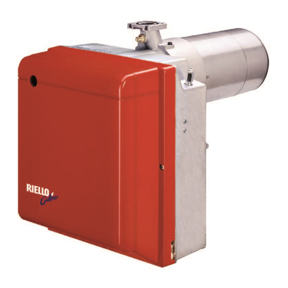
- Seite 1 Istruzioni per installazione, uso e manutenzione Montage und Bedienungsanleitung Installation, use and maintenance instructions Bruciatore di gas ad aria soffiata Gas-Gebläsebrenner Forced draught gas burner Funzionamento bistadio Zweistufiger Betrieb Two stage operation CODICE MODELLO - MODELL TIPO - TYP CODE MODEL TYPE 3762050...
-
Seite 3: Descrizione Del Bruciatore
INDICE DESCRIZIONE DEL BRUCIATORE . . . 3.5.2 Collegamenti elettrici con controllo Materiale a corredo ....tenuta valvole ..... DATI TECNICI . -
Seite 4: Dati Tecnici
DATI TECNICI DATI TECNICI TIPO 922 T1 ÷ ÷ Potenza termica (1) 160/208 345 kW – 137.600/178.800 296.700 kcal/h ÷ ÷ Pci: 8 12 kWh/Nm = 7000 10.340 kcal/Nm Gas naturale (Famiglia 2) Pressione: min. 20 mbar max. 100 mbar ±... -
Seite 5: Campo Di Lavoro
CAMPO DI LAVORO (secondo EN 676) D4357 130.000 170.000 210.000 250.000 290.000 kcal/h Potenza termica CALDAIE DI PROVA Il campo di lavoro è stato ottenuto su caldaie di prova secondo la norma EN 676. CALDAIE COMMERCIALI L’abbinamento bruciatore-caldaia non pone problemi se la caldaia è conforme alla norma EN 303 e le dimensioni della sua camera di combustione sono prossime a quelle previste nella norma EN 676. -
Seite 6: Fissaggio Alla Caldaia
INSTALLAZIONE L’INSTALLAZIONE DEL BRUCIATORE DEVE ESSERE EFFETTUATA IN CONFORMITÀ ALLE LEGGI E NORMATIVE LOCALI. FISSAGGIO ALLA CALDAIA ♦ Allargare, se necessario, i fori dello schermo isolante (3), (vedi fig. 3). ♦ Fissare alla portina della caldaia (1) la flangia (5) mediante le quattro viti (4) e ( se necessario ) i dadi (2) interponendo lo schermo isolante (3) ma tenendo allentata una delle due viti superiori (4, fig. -
Seite 7: Linea Di Alimentazione Gas
LINEA DI ALIMENTAZIONE GAS Fig. 6 – Condotto arrivo gas – Saracinesca manuale (a carico dell’installatore) – Manometro pressione gas (a carico dell’installatore) – Filtro – Pressostato gas – Valvola di sicurezza – Stabilizzatore di pressione – Valvola di regolazione 1° e 2° stadio D5208 M1 –... -
Seite 8: Collegamenti Elettrici
COLLEGAMENTI ELETTRICI 3.5.1 COLLEGAMENTI ELETTRICI STANDARD Nero Bianco D4367 Interruttore generale LEGENDA – Segnalazione funz. 2° stadio – Condensatore CN1 – Connettore sonda – Elettrodo 230V ~ 50Hz – Contaore 1° stadio – Contaore 2° stadio – Motore ATTENZIONE PA – Pressostato aria Non scambiare il neutro con la fase e rispettare esattamente lo PG –... - Seite 9 3.5.2 COLLEGAMENTI ELETTRICI CON CONTROLLO TENUTA VALVOLE (DUNGS VPS 504) 230V 50Hz D4371 230V ~ 50Hz Collegare il termostato 2° stadio ai morsetti T6 e T8 togliendo il ponte. LEGENDA B5 – Segnalazione funz. 2° stadio T6A – Fusibile V12 – Valvola 2° stadio h1 –...
-
Seite 10: Potenza All'accensione
FUNZIONAMENTO POTENZA ALL’ACCENSIONE Fig. 9 L’accensione deve avvenire a potenza ridotta e non superiore ai 120 kW. Per misurare la potenza all'accensione: – Scollegare il connettore (CN1) sul cavo della sonda di ionizzazione (vedi collegamenti elettri- ci a pag. 6) ; il bruciatore si accende e va in blocco dopo il tempo di sicurezza (3s). -
Seite 11: Regolazione Servomotore Serranda Aria
ESTRAZIONE GRUPPO TESTA, (vedi fig. 9, pag. 8) Per l’estrazione del gruppo testa eseguire le seguenti operazioni: Estrarre il gruppo porta testa (1) dopo aver tolto le viti (7), sconnesso i collegamenti (3 e 5), sfilato il tubetto (4) e allentato le viti (8). Si raccomanda di non alterare la posizione di regolazione staffa–gomito nella fase di smontaggio. -
Seite 12: Programma Di Avviamento
CORRENTE DI IONIZZAZIONE Connettore La corrente minima per far funzionare Fig. 10 l’apparecchiatura è 5 µA. Il bruciatore dà una corrente nettamente Morsettiera apparecchiatura superiore, tale da non richiedere normal- Sonda D5006 mente alcun controllo. Qualora, comun- que, si voglia misurare la corrente di ionizzazione bisogna aprire il connettore (CN1) (vedi schema elettrico pag. -
Seite 13: Difficoltà Di Avviamento
ANOMALIE / RIMEDI Si elencano alcune cause e i possibili rimedi a una serie di anomalie che potrebbero verificarsi e portare ad un mancato o non regolare funzionamento del bruciatore. Un’anomalia, nel funzionamento nella maggior parte dei casi, porta alla accensione della segnalazione all’interno del pulsante di sblocco dell’apparecchiatura di comando e controllo (4, fig. -
Seite 14: Anomalie In Funzionamento
ANOMALIE POSSIBILE CAUSA RIMEDIO Provvedere a una corretta regolazione L’elettrodo di accensione è mal po- secondo quanto indicato in questo ma- sizionato. nuale. Avviamento del bru- ciatore con ritardo di Regolare la portata dell’aria secondo Portata dell’aria troppo elevata. accensione. quanto indicato in questo manuale. -
Seite 15: Inhaltsverzeichnis
INHALT BESCHREIBUNG DES BRENNERS ..3.5.2 Elektrisches Verdrahtungsschema mit Dicht- Mitgeliefertes Zubehör ....heitskontrolle der Ventile ....7 TECHNISCHE MERKMALE . -
Seite 16: Technische Merkmale
TECHNISCHE MERKMALE 2.1 TECHNISCHE DATEN 922 T1 ÷ ÷ Brennerleistung (1) 160/208 345 kW – 137.600/178.800 296.700 kcal/h ÷ ÷ Unterer Heizwert: 8 12 kWh/Nm = 7000 10.340 kcal/Nm Erdgas (Familie 2) Anschlussdruck: Min. 20 mbar Max. 100 mbar ± Stromversorgung Einphasig, 230 V 50Hz... -
Seite 17: Arbeitsfeld
2.3 ARBEITSFELD (nach EN 676) D4357 130.000 170.000 210.000 250.000 290.000 kcal/h Brennerleistung PRÜFKESSEL Das Arbeitsfeld wurde an einem Prüfkessel, gemäß der Norm EN 676, ermittelt. HANDELSÜBLICHE HEIZKESSEL Die Abstimmung Brenner-Kessel ist ohne Probleme, wenn der Kessel der Euronorm EN 303 entspricht und die Abmessungen des Feuerraumes mit Euronorm EN 676 übereinstimmen. -
Seite 18: Installation
INSTALLATION DIE INSTALLATION DES BRENNERS MUSS IN ÜBEREINSTIMMUNG MIT DEN ÖRTLICHEN GESETZEN UND VORSCHRIFTEN AUSGEFÜHRT WERDEN. 3.1 BRENNERMONTAGE ♦ Falls erforderlich, die Bohrungen der Isolierdichtung (3) erweitern (siehe Abb. 3). ♦ Mit den Schrauben (4) ( falls erforderlich ) den Muttern (2) an der Kesseltür (1) den Flansch (5) mit Iso- lierdichtung (3) montieren, aber eine der zwei höheren Schrauben losschrauben (siehe Abb. -
Seite 19: Gasanschluss-Schema
GASANSCHLUSS–SCHEMA Fig. 6 1 – Gaszuleitung 2 – Handabsperrschieber (Sonderzubehör) 3 – Gasdruckmanometer (Sonderzubehör) 4 – Filter 5 – Gasdruckwächter 6 – Sicherheitsventil 7 – Gasdruckregler 8 – Einstellventil 1. und 2. Stufe M1 – Messung, Anschlußdruck D5208 M2 – Messung, Brenner- Kopfdruck GASSTRECKE ENTSPRECHEND EURONORM EN 676 GASSTRECKE ANSCHLÜSSE... -
Seite 20: Elektrisches Verdrahtungsschema
3.5 ELEKTRISCHES VERDRAHTUNGSSCHEMA 3.5.1 ELEKTRISCHES STANDARDVERDRAHTUNGSSCHEMA Schwarz Weiß Blau D4367 LEGEND Hauptschalter – 2. Stufe Betrieb-Fernmeldung – Kondensator CN1 – Kabelverbinder Flammenfühler – Zündelektrode 230V ~ 50Hz – 1. Stufe Stundenzähler – 2. Stufe Stundenzähler ACHTUNG – Motor Nulleiter und Phase nicht vertauschen und das o.g. elektrische –... -
Seite 21: Elektrisches Verdrahtungsschema Mit Dichtheitskontrolle Der Ventile
3.5.2 ELEKTRISCHES VERDRAHTUNGSSCHEMA MIT DICHTHEITSKONTROLLE DER VENTILE (DUNGS VPS 504) 230V 50Hz D4371 230V ~ 50Hz 2. Stufe Thermostat zwischen T6 und T8 Klemmen anschliessen, dabei die Brücke entfernen. LEGENDE B5 – 2. Stufe Betrieb-Fernmeldung T6A – Sicherung V12 – 2. Stufe Ventil TL –... -
Seite 22: Betrieb
BETRIEB ZÜNDLEISTUNG Abb. 9 Die Zündung Muß mit reduzierter Leistung und nicht über 120 kW gescheben. – Den Verbinder (CN1) vom Kabel der Ionisati- onssonde abtrennen (siehe Elektrisches Ver- drahtungsschema auf Seite 6) ; der Brenner schaltet ein und geht nach der Sicherheitszeit (3s) in Störabschaltung. -
Seite 23: Einstellung Des Luftklappen-Stellantriebs
ENTNAHME DES KOPFBLOCKS , (siehe Abb. 9, Seite 8) Um den Kopfblock-Halter herauszunehmen, die folgenden Tätigkeiten ausführen: den Kopf herausnehmen, nachdem vorher die Schrauben (7) weggenommen, die Verbindungen (3 und 5) getrennt, das Röhrchen (4) abgenommen und die Schrauben (8) gelockert wurden. Es wird empfohlen, nicht die Einstellspindellage und den Schlitten während der Demontage zu ändern. -
Seite 24: Betriebsablauf
IONISATIONSSTROM Kabelverbinder Abb. 10 Der Betrieb des Steuergerätes erfordert einen Ionisationsstrom von mindenstens 5 µA. Da unter normalen Bedingungen ein weitaus Klemmleiste des höhere Strom erzeugt wird, sind normaler- Steuergerätes Flammenfühler weise keine Kontrollen nötig. Wenn aber D5006 der Ionisationsstrom gemessen werden soll, muß... -
Seite 25: Störungen / Abhilfe
STÖRUNGEN / ABHILFE Nachfolgend finden Sie einige denkbare Ursachen und Abhilfemöglichkeiten für Störungen, die den Betrieb des Brenners beeinflussen oder einen nicht ordnungsgemäßen Betrieb des Brenners verursachen könnten. In den meisten Fällen führt eine Störung zum Aufleuchten der Kontrolleuchte in der Entstörtaste des Steuergeräts (4, Abb. -
Seite 26: Betriebsstörungen
STÖRUNGEN MÖGLICHE URSACHE ABHILFE Zündelektrode nicht in richtiger Gemäß den Angaben dieser Anlei- Position. tung korrekt einstellen. Anfahren des Bren- Gemäß den Angaben dieser Anlei- ners mit verspäteter Zu höher Luftdurchsatz. tung den Luftdurchsatz einstellen. Zündung. Zu geschlossene Ventilsbremse mit Einstellen. -
Seite 27: Burner Description
INDEX BURNER DESCRIPTION ... . 3.5.2 Electrical wiring with gas leak control 1.1 Burner equipment ....device . -
Seite 28: Technical Data
TECHNICAL DATA 2.1 TECHNICAL DATA TYPE 922 T1 Thermal power (1) 160/208 345 kW – 137,600/178,800 296,700 kcal/h Net heat value: 8 – 12 kWh/Nm 3 = 7000 – 10,340 kcal/Nm 3 Natural gas (Family 2) Pressure: min. 20 mbar max. -
Seite 29: Test Boiler
2.3 FIRING RATE, (as EN 676) D4357 130,000 170,000 210,000 250,000 290,000 kcal/h Thermal power TEST BOILER The firing rate has been defined according to EN 676 standard. COMMERCIAL BOILERS The burner-boiler matching is assured if the boiler is according to EN 303 and the combustion chamber dimensions are similar to those shown in the diagram EN 676.For applications where the boiler is not according to EN 303, or where the combustion chamber dimensions differ from those shown in EN 676, please consult the manufacturers. -
Seite 30: Boiler Fixing
INSTALLATION THE BURNER MUST BE INSTALLED IN CONFORMITY WITH LEGISLATION AND LOCAL STANDARDS. 3.1 BOILER FIXING ♦ Widen, if necessary, the insulating gasket holes (3) (see fig. 3). ♦ Fix the flange (5) to the boiler door (1) using four screws (4) and (if necessary) the nuts (2) interposing the insulating gasket (3) but keep unloosing one of the two upper screws (4) (see fig. - Seite 31 GAS FEEDING LINE Fig. 6 – Gas supply pipe – Manual cock (charged to the installer) – Gas pressure gauge (charged to the installer) – Filter – Gas pressure switch – Safety valve – Pressure governor – 1 st and 2 nd adjusting valve D5208 M1 –...
-
Seite 32: Electrical Wiring
3.5 ELECTRICAL WIRING 3.5.1 STANDARD ELECTRICAL WIRING Black White Blue D4367 Main switch KEY TO LAY-OUT – 2 stage working signal – Capacitor CN1 – Connector ionization probe – Electrode 230V ~ 50Hz – 1 stage hour counter – 2 stage hour counter ATTENTION –... - Seite 33 3.5.2 ELECTRICAL WIRING WITH GAS LEAK CONTROL DEVICE (DUNGS VPS 504) 230V 50Hz D4371 230V ~ 50Hz Connect 2 stage thermostat between clamps T6 and T8 removing the bridge. KEY TO LAY-OUT T6A – Fuse – 2 stage working signal V12 –...
-
Seite 34: Firing Output
WORKING FIRING OUTPUT Fig. 9 The firing must occur at reducer output and not higher than 120 kW. In order to measure the firing output: – Disconnect the connector (CN1) on the ioniza- tion probe cable (see electrical wiring at page 6) ; the burner will fire and then go into lock-out after the safety time (3s) has elapsed. -
Seite 35: First Stage
REMOVING HEAD ASSEMBLY, (see fig. 9, page 8) To remove the head assembly, carry out the following operations: Remove the head-holder assembly (1), after taking away the screws (7), disconnect the connections (3 and 5), extract the small tube (4) and loosen the screws (8). Do not modify the setting position of the bracket-elbow during the disassembly. -
Seite 36: Burner Start-Up Cycle
IONIZATION CURRENT Connector The minimum current necessary for the Fig. 10 control box operation is 5 µA. The burner normally supplies a higher cur- Terminal block rent value, so that no check is needed. of control-box Probe Anyway, if you want to measure the ioni- D5006 zation current, you have to open the con- nector (CN1) (see electrical scheme page 6) fitted on the wire and insert a microammeter, (see fig. - Seite 37 FAULTS / SOLUTIONS Here below you can find some causes and the possible solutions for some problems that could cause a fail- ure to start or a bad working of the burner. A fault usually makes the lock-out lamp light which is situated inside the reset button of the control box (4, fig.
-
Seite 38: Operating Faults
FAULTS POSSIBLE CAUSES SOLUTION The ignition electrodes is wrongly Adjust it according to the instructions positioned. of this manual. The burner starts with Set the air output according to the Air output is too high. an ignition delay. instructions of this manual. Valve brake is too close with insuffi- Adjust it.