Werbung
Verfügbare Sprachen
Verfügbare Sprachen
Quicklinks
Commissioning
Surface Mount Variant
DDF4010HDV-SM
DDF4 1 10HDV-SM
DK 150.000 / Rev. 1.0.0 / 091216
Securing screw
Plug-in module
(spring clip 1)
Securing screw
(spring clip 2)
Spring clip 1
Spring clip 2
3-axis mount
(pan / tilt / rotation)
TELE button
WIDE button
Fig. 4 Plug-in module
Ceiling/Wall
Drill hole
Anchor
Mounting screw
(Ø 4 mm)
Fig. 5
11
7
3
9
5
1
10
6
2
Weidmüller male connector
12
8
4
SL 3.50/02/90G
Fig. 6 Terminal area
© 2009 Dallmeier electronic
All rights reserved.
We reserve the right to make technical modifications.
All trademarks identified by ® are registered trademarks of Dallmeier electronic.
English
All trademarks identified by *) are trademarks or registered trademarks of the following owners:
Adobe and Flash of Adobe Systems Incorporated headquartered in San José, California, USA
IBM of International Business Machines Corporation headquartered in Armonk, New York, USA
Microsoft, ActiveX, DirectX, Internet Explorer, Windows and Windows Vista of Microsoft Corporation
headquartered in Redmond, Washington, USA
Dallmeier electronic GmbH & Co.KG
Cranachweg 1, 93051 Regensburg, Germany
www.dallmeier.com / info@dallmeier.com
Safety Instructions
Only use this unit if it is technically in proper working order, to the intended pur-
pose and while keeping safety and potential dangers in mind!
Read and pay attention to the documents!
Observe the rated voltage! Observe ratings!
WARNING
Device falling off or collapsing ceiling
Danger of death or serious injury to the head
¾ Observe the manufacturer's instructions about the maximum
adequate carrying capacity of the supporting structure.
¾ Use screws suitable for the ceiling/wall material.
¾ Use the correct type of anchor for your ceiling/wall type:
• Plastic screw anchors for solid wall material (concrete/brick)
• Toggle bolt style anchors for drywall / hollow wall type (plaster)
Electric shock hazard
Danger of death or serious injury
¾ Disconnect the power supply unit from the mains socket before
connecting the device.
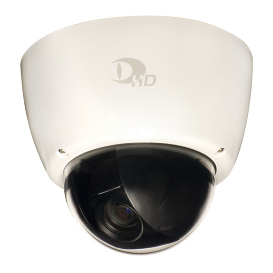
Appropriate Use
The DDF4010HDV-SM / DDF4110HDV-SM is a vandal-resistant High Definition
IP dome camera. It is designed for indoor installations on ceilings and
walls and can be operated via PoE (Power over Ethernet, Class 0) or at 24 V AC.
Pin No.
Assignment
Pin No.
1
Rx+
2
3
Tx+
4
5
GP Out
6
7
GP In 1
8
9
GP In 2
10
11
GP In 3
12
Installation and Commissioning
The housing base is mounted with 3 screws (Ø 4 mm) to the ceiling/wall.
¾ Unscrew the 3 housing screws using a T20 torx wrench and remove the hous-
ing (Fig. 1).
¾ Unscrew the securing screws of the spring clips and remove the plug-in module
while pushing the spring clips slightly together (Fig. 3).
¾ Mark the drill holes on the ceiling/wall (Fig. 5) using the 3 pre-drilled mounting
holes of the housing base (Fig. 2) as a template.
¾ At the marked locations, drill holes fitting for the screws/anchors to be used.
¾ Push anchors suitable for the ceiling/wall material in the drill holes (Fig. 5).
¾ Run the required cables suspended from the ceiling/wall through a PG16 cable
gland.
¾ Screw the PG16 cable gland in the appropriate thread of the housing
base (Fig. 2).
¾ Connect the required cables to the connectors of the terminal area (Fig. 6) in
the housing base (Fig. 1).
¾ Mount the housing base with 3 screws to the ceiling/wall (Fig. 5).
¾ Insert the plug-in module carefully into the housing base (Fig. 1) until it clicks
into place. The number of the spring clips must match the number of the slots.
¾ Secure the plug-in module.
For this purpose tighten the 2 securing screws of both spring clips (Fig. 3).
¾ Connect the power supply unit to the mains socket.
¾ Connect a CVBS monitor to the video preview output (Fig. 3).
¾ Adjust the lens using the 3-axis mount and set the focal length with the
TELE / WIDE buttons (Fig. 4).
The "Little Man" symbol on the lens side indicates the sensor direction.
¾ Disconnect the CVBS monitor.
¾ Attach the housing to the housing base and tighten the 3 housing screws using
a T20 torx wrench.
Views and Connection Assignment
Thread for
PG16 cable gland
Slot 2 for
spring clip 2
Terminal area
Securing screw
(spring clip 2)
Spring clip 2
Plug-in module
Lens
Connection
Assignment
The configuration of the device is carried out with a PC/web browser via the local
Rx−
area network (LAN).
Tx−
GND I/O
Alternatively, the PC can be directly connected to the device via an Ethernet
GND I/O
crossover cable.
GND I/O
The factory default IP address of the device is 192.168.2.28.
GND I/O
Minimum System Requirements
Computer
Processor (CPU)
Random Access Memory (RAM)
Operating System
Web Browser
Graphics Card
Ethernet
Software
¾ Ensure that the PC/web browser can establish a connection to the device via
Ethernet.
¾ Start the web browser.
¾ Enter the IP address of the device into the address bar of the web browser.
¾ Confirm the input.
The connection to the device is established.
The graphical user interface (GUI) of the live mode is displayed.
Login
The factory default password of user group Group 1: admin is "3".
¾ Click CONFIG in the user interface of the live mode.
¾ Enter the Username if required.
¾ Enter the Password.
¾ Confirm with OK.
The graphical user interface of the configuration mode is displayed.
¾ Configure the required settings and finally click LOGOUT.
Thread for housing screw
Housing base
Terminal area
Slot 1 for
Thread for housing screw
spring clip 1
Securing screw
(spring clip 2)
Mounting hole for
Ø 4 mm screw
Video preview output
(3.5 mm phone jack)
USB / SD port
Housing with bubble
Video preview output
(3.5 mm phone jack)
Housing screw
(T20 Torx)
Fig. 1
Technical Data
Sensor
Image Resolution
Lens
Horizontal Angle of View
IR Filtering
Video / Audio Compression
HD Standards
IBM
-PC compatible
*)
1.3 GHz
Frame Rate
256 MB
Microsoft
*)
Windows
*)
2000
Video / Audio Bit Rate
Microsoft Windows XP
Resolution
Windows Vista
*)
each with latest service pack
Video Streaming
Microsoft Internet Explorer
, latest version
*)
DirectX
9.0 compatible
*)
100 Mbps
Multi Streaming Frame Rate
Adobe
*)
Flash
*)
Player, latest version
Video OUT
Dallmeier control for ActiveX
*)
, latest version
Audio IN
Audio OUT
Ethernet
Ethernet Protocols
Local Video Memory
Video Buffer
Contact IN / Relay OUT
Serial
Programming Interface
Video Standard
Voltage Supply
PoE Conformity
Power Consumption
Dimensions
Weight
Operating Temperature
Humidity
IP Rating
Approvals/Certifications
Slot 1 for
Mounting hole for
spring clip 1
Ø 4 mm screw
Thread for housing screw
Mounting hole for
Ø 4 mm screw
Housing base
Thread for housing screw
Thread for
Slot 2 for
PG16 cable gland
spring clip 2
Fig. 2 Housing base
Spring clip 1
Securing screw
Securing screw
(spring clip 1)
(spring clip 1)
Plug-in module
USB / SD port
Lens
Securing screw
Securing screw
(spring clip 2)
(spring clip 2)
Spring clip 2
Fig. 3 Plug-in module
1/3" Full High Definition CMOS image sensor
with
technology
DDF4010HDV-SM: Up to 1920 × 1080 (Full HD)
DDF4110HDV-SM: Up to 1280 × 720 (HD)
F1.8 – F2.1 / 5.1 – 51 mm
Approx. 50° – 5.4°
Built-in IR cut filter
H.264, MJPEG / G.722, MPEG-1 Layer 2
DDF4010HDV-SM: SMPTE 296M, SMPTE 274M
DDF4110HDV-SM: SMPTE 296M
DDF4010HDV-SM: Up to 50 fps
DDF4110HDV-SM: Up to 30 fps
Up to 16 Mbps (6 Mbps typical) / Up to 384 kbps
DDF4010HDV-SM: SD, HD (720p, 1080i, 1080p)
DDF4110HDV-SM: SD, HD (720p)
Simultaneous multi-streaming: H.264 and MJPEG
(with independently adjustable resolutions,
frame and bit rates of each stream)
Up to 25 fps at maximal resolution
1× 3.5 mm phone jack
(analogue SD video preview output, CVBS)
1× 3.5 mm phone jack (Line-In, stereo)
1× 3.5 mm phone jack (Line-Out stereo)
1× RJ45, 10BASE-T-/100BASE-TX-PoE
IPv4, TCP, UDP, ARP, ICMP, DHCP, NTP, HTTP,
RTSP, IGMP V2, RTP, RTCP
Via integrated USB / SD port
64 MB RAM ring storage
(pre- and post alarm, network failure compensation)
3× IN / 1× OUT
1× RS485 (full-duplex)
Open API for 3rd party systems integration via
Dallmeier control for ActiveX
HDTV, SDTV (PAL / NTSC)
24 V AC ±10% (50 / 60 Hz) or via PoE (Class 0)
IEEE 802.3af (no PoE adapter required)
24 V AC: max. 15.2 W, PoE (Class 0): max. 12.94 W
Approx. Ø 186 × H 161 mm
Approx. 2000 g
−10 °C to +40 °C
0 % – 90 % RH non-condensing
IP67
CE, FCC, UL, ACA, CB,
DIN EN 50130-4 compliant
Werbung

Verwandte Anleitungen für dallmeier DDF4110HDV-SM


Inhaltszusammenfassung für dallmeier DDF4110HDV-SM
- Seite 1 Slot 1 for We reserve the right to make technical modifications. Mounting hole for spring clip 1 Ø 4 mm screw All trademarks identified by ® are registered trademarks of Dallmeier electronic. Thread for Thread for housing screw PG16 cable gland English...
- Seite 2 Gewinde für Gehäuseschraube Aufnahme 1 für Technische Änderungen vorbehalten. Befestigungsloch für Federbügel 1 Ø 4 mm Schraube Mit ® gekennzeichnete Marken sind eingetragene Marken von Dallmeier electronic. Gewinde für Gewinde für PG16 Kabelverschraubung Deutsch Gehäuseschraube Mit *) gekennzeichnete Marken sind Marken oder eingetragene Marken folgender Eigentümer: Gehäuseboden...