Werbung
Quicklinks
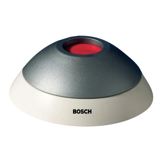
Überfalltaster
Hold-up contact
ND 100 GLT
Installationshinweis
Installations Notes
Anschlüsse
Connections
I4
I5
⊥ ⊥ ⊥ ⊥
/SA
I3
SK
+U/SR
I2
NLT2/SM
SK
-U/AR
ÜK
⊥ ⊥ ⊥ ⊥
/AA
ÜK
I1
NLT1/AM
R
= abhängig von EMZ
E
Terminal resistance = depends on
intrusion detection control center.
1
Anschlußdrähte mit Isolierschlauch überziehen
Pull insulation sleeving over leads.
–
§ Druckknopf soweit eindrücken, bis sich die Kappe durch Linksdrehung entriegeln und abheben läßt.
§ Press in button until you can disengage the cap by turning it to the left and then lift it off.
—
§ Gehäuseoberteil durch Zusammendrücken der beiden Halteklammern vom Gehäuseunterteil trennen.
§ Remove the upper section of the housing from the lower section by pressing the two retaining clips together.
Anschaltung
Connection
M
n
R
1
E
I6
M
n
R
I7
E
1
1
Halteklammer
Retaining clip
- 1 -
Umweltklasse 2
Env. Class 2
VdS-Anlagenklasse C
VdS plant class C
VdS-Nr. G 195065
VdS No. G 195065
M
1
M
1
1
610-3.902.115.341
A6 März. 2001
EMZ
b
Sabotage
Tamper
a
b
Überfall
Hold-up
a
EMZ
b
Alarm
Alarm
a
Werbung

Inhaltszusammenfassung für Bosch ND 100 GLT
- Seite 1 Überfalltaster Hold-up contact ND 100 GLT Installationshinweis Umweltklasse 2 Env. Class 2 VdS-Anlagenklasse C VdS plant class C Installations Notes VdS-Nr. G 195065 VdS No. G 195065 Anschaltung Connection Sabotage Tamper Anschlüsse Connections Überfall Hold-up ⊥ ⊥ ⊥ ⊥ +U/SR...
- Seite 2 ˜ § Zum Bohren der Befestigungslöcher (∅ 4 mm) Gehäuseunterteil als Schablone verwenden. Dübel S4 einsetzen und Gehäuse- unterteil mit Holzschrauben (3 x 25 bzw. 3,5 x 25) befestigen. § Use the lower section of the housing as a template for drilling the fastening holes (∅ 4 mm). Use an S4 dowel to secure the bottom section of the housing with wood screws (3 x 25 or 3.5 x 25).


