Kapitel
Inhaltsverzeichnis

Verwandte Anleitungen für Avdel 753 MkII type


Inhaltszusammenfassung für Avdel 753 MkII type
- Seite 1 B e t r i e b s a n l e i t u n g Üb e r s e t z u n g d e r O r i g i n a l - B e t r i e b s a n l e i t u n g 7 5 3 M k I I t y p e 7 5 3 0 - 0 7 5 3 2 O u t i l o l é...
-
Seite 3: Inhaltsverzeichnis
Garantiezeit geöffnet wurde. Bei Defekten oder Störungen repariert oder ersetzt Avdel nur fehlerhafte Komponenten nach eigenem Ermessen. Im Rahmen der Geschäftspolitik der ständigen Produktentwicklung und -verbesserung behält sich Avdel das Recht vor, Spezifikationen ohne vorherige Ankündigung zu ändern. -
Seite 4: Sicherheitsvorschriften
Mit diesem Gerät/dieser Maschine keine anderen als die von Avdel empfohlenen und gelieferten Ausrüstungen verwenden. Für jede vom Kunden durchgeführte Änderung an Gerät/Maschine, Mundstücken, Zubehör und anderen von Avdel oder von ihren Vertretern gelieferten Einzelteilen ist der Kunde alleine verantwortlich. Avdel wird Sie bei allen geplanten Veränderungen gerne beraten. -
Seite 5: Technische Daten
Te c h n i s c h e D a t e n Te c h n i s c h e D a t e n f ü r G e r ä t Ty p 7 5 3 M k I I Betriebsdruck min./max. -
Seite 6: Arbeitsbereich
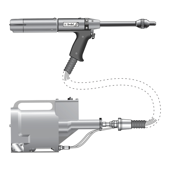
A r b e i t s b e re i c h ® ® Das Druckluftgerät 0753 MkII wurde für das Setzen von Avdel Magazinznieten (ausgenommen 1/16” Avlug ) konstruiert. Es eignet sich deshalb ideal für die Serien- und Fließmontage mit den verschiedensten Einsatzzwecken in allen Industriezweigen. -
Seite 7: Geräteabmessungen
A r b e i t s b e re i c h G e r ä t e a b m e s s u n g e n - M o d e l l 0 7 5 3 0 M k I I Artikelnummer 07530-02100 G e r ä... -
Seite 8: Inbetriebnahme
I n b e t r i e b n a h m e D r u c k l u f t v e r s o rg u n g Der Betrieb aller Geräte erfolgt durch Druckluft mit einem optimalen Druck von 5,5 bar. Wir empfehlen den Einsatz von Druckreglern und automatischen Öl-/Filtersystemen für die Hauptdruckluftversorgung. -
Seite 9: Mechanische Rücklaufsperre
I n b e t r i e b n a h m e M e c h a n i s c h e R ü c k l a u f s p e r r e FEDERBEAUFSCHLAGTES ENDE LAUF RÜCKLAUFSPERRE... -
Seite 10: Laden Und Nachladen Des Gerätes
Inbetriebnahme R ü c k l a u f s p e r r e WICHTIG Bei falschem Einbau macht die Rücklaufsperre die Zuführung der Niete unmöglich. Obgleich die Rücklaufsperre bei Lieferung des Gerätes richtig herum eingebaut wurde, empfehlen wir vor Anbau der Ausrüstung ihre Einbaulage zu prüfen. -
Seite 11: Arbeitsvorgang
Inbetriebnahme Laden des Gerätes • Die Druckluftversorgung am Gerät anschließen. • Die Spannbacken 9 zum Spannen des Dorns öffnen. Zu diesem Zweck das Schaltventil abschalten (Pos. 26 und 30). • Das gewählte Mundstück auf den Lauf 25 des Gerätes aufschrauben. Einen Nietdorn durch das Papiermagazin gegen das hintere Ende der Niete einsetzen. -
Seite 12: Kennzeichnung Und Lage Der Nietdornfedern
I n b e t r i e b n a h m e KENNZEICHNUNG UND LAGE DER NIETDORNFEDERN BEZEICHNUNG NIETDORN-/NIETDORNFEDERN- MUNDSTÜCK NIETDORN- UND NIETBAUGRUPPE GRÖSSE NIET GRÖSSE (SIEHE ABSCHNITT ÜBER AUSRÜSTUNG) NIETDORNFEDER FEDER UND KAPPENBILDEN EINE EINHEIT NIETDORN NIETDORNKOPF 3 /32"... -
Seite 13: Ausrüstungen
A u s r ü s t u n g e n Auf Magazinnietgeräten wie Modell 0753 Mk II besteht die Ausrüstung stets aus drei Konponenten: einem Mundstück, einem Nietdorn und einer Nietdornfeder. Diese drei Teile müssen zum gesetzten Niet und zum Lochdurchmesser passen. W I C H T I G Um ein vollständiges Zerlegen des Gerätes zu vermeiden, ist es notwendig, die Orientierung der Rücklaufsperre vor Einbau der Ausrüstung zu prüfen (siehe Abschnitt "RÜCKLAUFSPERRE"... -
Seite 14: Auswahl Eines Mundstücks
A u s r ü s t u n g e n A u s w a h l e i n e s M u n d s t ü c k s • Bezeichnung, Größe und Werkstoff des zu setzenden Niets auflisten. •... - Seite 15 A u s r ü s t u n g e n A u s w a h l d e s M u n d s t ü c k s - Z o l l m a s s Die Spalte "BEZ.-NR."...
- Seite 16 A u s r ü s t u n g e n A u s w a h l d e s M u n d s t ü c k s - M e t r i s c h e M a s s e MUNDSTÜCK MUNDSTÜCK BEZ.
-
Seite 17: Chobert ® Und Grovit ® Auswahltabellen
Verantwortung sicherzustellen, daß Nietdorne ersetzt werden, bevor ein übermäßiger Verschleiß auftritt sowie stets vor Erreichen der höchstzulässigen Anzahl von Nietungen. Setzen Sie sich bitte mit Ihrem Avdel- Vertreter in Verbindung, der Ihnen den Wert bekanntgeben wird, nachdem er die Setzkraft Ihrer Anwendung mit unserem Prüfgerät zur Setzkraftmessung gemessen hat. - Seite 18 A u s r ü s t u n g e n Die unten links und rechts sowie auf den nächsten vier Seiten abgedruckten Tabellen enthalten eine Auflistung der Teilnummern für alle Nietdorne und Nietdornfedern pro Niet oder Nietengruppe, z.B. für Chobert ®...
- Seite 19 A u s r ü s t u n g e n Um die korrekte Teilnummer eines Nietdorns für eine besondere Anwendung aufzufinden, die nachstehenden Anweisungen lesen, nachdem die Angaben entsprechend dem nebenstehenden Beispiel festgestellt wurden. Die Antworten für das Beispiel sind in grauer Kursivschrift gedruckt.
- Seite 20 A u s r ü s t u n g e n N i e t d o r n k o p f a r t e n u n d L ä n g e “ P ” Nietdorne für Briv ®...
- Seite 21 A u s r ü s t u n g e n ® ® ® ® Avlug , Avsert , Avtronic & Rivscrew - Zollmass & Metrische Masse Für die Auswahl von Nietdorn oder Nietdornfeder die Anweisungen auf Seite 94 befolgen. STANDARD-NIETDORN - GRÜN NIETDORN FÜR 1.
-
Seite 22: Wartung Des Gerätes
Wartung des Gerätes Die Wartung ist in regelmäßigen Zeitabständen durchzuführen. Eine umfangreiche Prüfung ist jährlich oder alle 500.000 Arbeitstakte durchzuführen, je nachdem, was früher eintritt. W I C H T I G Der Arbeitgeber trägt die Verantwortung, sicherzustellen, daß die Gerätewartungsanweisungen dem entsprechenden Personal ausgehändigt werden. -
Seite 23: Werkzeugsatz
Wartung des Gerätes W e r k z e u g s a t z Wir empfehlen die Verwendung des nachstehenden Werkzeugsatzes für alle Wartungsarbeiten (Teilnummer 07900-05300). WERKZEUGSATZ ART-NR. BENENNUNG POS. ART-NR. BENENNUNG POS. 07900-00157 SICHERUNGSRINGEZANGE 07900-00352 DICHTRINGAUSZIEHHAKEN 07900-00006 MONTIERHEBEL 07900-00710 STECKSCHLÜSSELEINSATZ 13 mm 07900-00446... - Seite 24 Wa r t u n g Alle 500 000 Arbeitstakte sollte das Gerät vollständig zerlegt werden. Verschlissene, beschädigte oder andere empfohlene Teile sind zu ersetzen. Alle Dichtringe und Dichtungen sind zu ersetzen und mit Molylithiumfett EP 3753 vor der Montage einzuschmieren. W I C H T I G Sicherheitsvorschriften erscheinen auf Seite 80.
- Seite 25 Wa r t u n g Z e r l e g e n 0 7 5 3 0 - 0 2 2 0 0 M k I I AUSLÖSERBAUGRUPPE • Um diese Baugruppe zu zerlegen/zu warten, die Abdeckungen wie vorher beschrieben vom Gerät entfernen. •...
- Seite 26 Wa r t u n g Z e r l e g e n 0 7 5 3 2 - 0 2 2 0 0 M k I I Für das Zerlegen von 07532-02200 Mk II siehe Seiten 100-101. SPANNBACKENZYLINDER •...
- Seite 27 Wa r t u n g Z e r l e g e n 0 7 5 3 0 - 0 2 2 0 0 M k I I AUSLÖSERBAUGRUPPE • Um diese Baugruppe zu zerlegen/zu warten, die Abdeckungen wie vorher beschrieben vom Gerät entfernen. •...
- Seite 28 Übersichtszeichnung der Nietpistole 07530-02200 MkII...
- Seite 29 Ersatzteilliste für Nietpistole 07530-02200 MkII...
- Seite 30 Übersichtszeichnung der Nietpistole 07532-02200 MkII...
- Seite 31 Ersatzteilliste für Nietpistole 07532-02200 MkII...
- Seite 32 D r u c k ü b e r s e t z e r 0 7 5 3 1 - 0 2 2 0 0 - Wa r t u n g D e m o n t a g e A n l e i t u n g •...
- Seite 33 D r u c k ü b e r s e t z e r 0 7 5 3 1 - 0 2 2 0 0 Note Diese Teile sind in einigen Geräten nicht enthalten. (Die erforderliche Verbindung wird über interne kanäle gewährleistet.
- Seite 34 Vo r s t e u e r v e n t i l 0 7 0 0 5 - 0 0 5 9 0 - Wa r t u n g A n l e i t u n g z u m D E M O N T A G E Bitte darauf achten, daß...
- Seite 35 † HINTERE KAPPE † KOLBEN † SCHRAUBE 07005-00590 VENTIL † PATRONE † SCHEIBE Diese Teile bilden zusammen einen Werkzeugsatz für das Ventil mit einer zusätzlichen Tube CENTOPLEX-2-Fett. Der Satz wird unter Teilnummer 07005-01538 von Avdel geliefert. † Nicht als Ersatzteil erhältlich...
- Seite 36 A u f f ü l l e n Nach dem Zerlegen des Gerätes und vor Inbetriebnahme ist IMMER ein Auffüllen erforderlich. Es kann auch notwendig werden, den vollen Hub nach längerem Gebrauch wiederherzustellen, wenn der Hub geringer geworden ist und Niete nicht vollständig durch einmaliges Betätigen des Auslösers gesetzt werden.
-
Seite 37: Beseitigen Von Störungen
Zuführung von mehr als Nietdornschlupf. Wie unter "Nietdornschlupf", Stufe 2, einem Niet. prüfen. Falscher Abstand zwischen Nietkopf und Abstand auf 1,5 - 3 mm einstellen (siehe Mundstück nach dem Laden. "Gerät laden"). Andere Symptome oder Störungen sind Ihrem zuständigen Avdel-Händler oder -Reparaturcenter mitzuteilen. - Seite 38 A n m e r k u n g e n...
-
Seite 39: Ausgabedatum
K o n f o r m i t ä t s e r k l ä r u n g Wir, Avdel UK Limited; Watchmead Industrial Estate, Welwyn Garden City, Hertfordshire, AL7 1LY erklären unter unserer alleinigen Verantwortung, dass das Produkt: Typ 0753 Mk II, Modelltypen 07530 - 07532 Handgerät Serien-Nr.