
Verwandte Anleitungen für Guntermann & Drunck FIBREVision


Inhaltszusammenfassung für Guntermann & Drunck FIBREVision
- Seite 1 Guntermann & Drunck GmbH www.gdsys.de G&D FIBREVision-USB 2.0 Installationsanleitung Installation Guide A9100153-1.20...
-
Seite 2: Zu Dieser Dokumentation
© Guntermann & Drunck GmbH 2011. Alle Rechte vorbehalten. Version 1.20 – 23.05.2011 Firmware: 1.9.006cpu; 1.8.004con Guntermann & Drunck GmbH Dortmunder Str. 4a 57234 Wilnsdorf Germany Telefon +49 (0) 2739 8901-100 Telefax +49 (0) 2739 8901-120 http://www.GDsys.de sales@GDsys.de i · G&D FIBREVision-USB 2.0... -
Seite 3: Inhaltsverzeichnis
Übertragungsreichweite zwischen den Modulen ............ 3 Zusätzliche Funktionen erweiterter Varianten ............. 3 Verfügbare Erweiterungen ................. 3 Lieferumfang ....................4 Standardlieferumfang der FIBREVision-USB 2.0-Serie ........4 Zusätzlicher Lieferumfang der erweiterten Varianten .......... 4 Installation ....................... 5 Vorbereitung ..................... 5 Installation des Rechnermoduls ................5 Anschluss des Rechners ................ -
Seite 4: Sicherheitshinweise
Betreiben Sie dieses Gerät nur mit dem mitgelieferten oder in der Bedienungs- anleitung aufgeführten Netzteil. ! Betreiben Sie das Gerät ausschließlich im vorgesehenen Einsatzbereich Die Geräte sind für eine Verwendung im Innenbereich ausgelegt. Vermeiden Sie extreme Kälte, Hitze oder Feuchtigkeit. 1 · G&D FIBREVision-USB 2.0... -
Seite 5: Besondere Hinweise Zum Umgang Mit Laser-Technologie
Sicherheitshinweise Besondere Hinweise zum Umgang mit Laser-Technologie Die Geräte der FIBREVision-Serie verwenden Baugruppen mit Laser-Technologie, die der Laser-Klasse 1 entsprechen. Sie erfüllen dabei die Richtlinien gemäß DIN EN 60825-1:2001-11, IEC 60825-1 sowie U.S. CFR 1040.10 und 1040.11. LASER KLASSE 1... -
Seite 6: Die Fibrevision-Usb 2.0-Serie
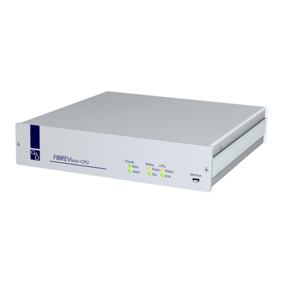
Die FIBREVision-USB 2.0-Serie Die FIBREVision-USB 2.0-Serie Die KVM-Extender der FIBREVision-USB 2.0-Serie übertragen die Signale von Tastatur, Maus und USB-Geräten sowie das Videosignal zwischen dem Arbeits- platz und dem entfernten Rechner. Ein FIBREVision-System besteht aus zwei wesentlichen Komponenten: An das Rechnermodul (FIBREVision-CPU) wird der zu bedienende ... -
Seite 7: Lieferumfang
1 × Servicekabel (Update-Cable-2) 1 × Installationsanleitung 1 × Bedienungsanleitung Zusätzlicher Lieferumfang der erweiterten Varianten Im Lieferumfang einer erweiterten Variante der FIBREVision-Serie befinden sich zusätzlich die unten aufgeführten Kabel. Varianten mit Audio- und RS232-Übertragung 2 × Audio-Kabel (Audio-M/M-2) ... -
Seite 8: Installation
2. Schalten Sie den am KVM-Extender anzuschließenden Rechner ggf. aus und ziehen Sie die Kabel von Monitor, Tastatur und Maus aus den Schnittstellen. 3. Platzieren Sie das Rechnermodul (FIBREVision-CPU) in der Nähe des Rechners. Die maximale Kabellänge zwischen dem Rechnermodul und dem anzuschlie- ßenden Rechner beträgt fünf Meter. -
Seite 9: Anschluss Des Rechners
Ist der Monitor mit einem analogen VGA-Eingang ausgestattet, stecken Sie einen optionalen Adapter auf diese Schnittstelle und schließen hieran das VGA-Kabel des Monitors an. Keyb.: Schließen Sie die PS/2-Tastatur des lokalen Arbeitsplatzes an. Schließen Sie die PS/2-Maus des lokalen Arbeitsplatzes an. Mouse: G&D FIBREVision-USB 2.0 · 6... -
Seite 10: Zusätzliche Schnittstellen Der Erweiterten Varianten
Das andere Ende des Kabels ist mit der Schnittstelle Transmission – Rx des Arbeits- platzmoduls zu verbinden. Transmission – Rx: Stecken Sie den LC-Stecker eines Glasfaserkabels ein. Das andere Ende des Kabels ist mit der Schnittstelle Transmission – Tx des Arbeits- platzmoduls zu verbinden. 7 · G&D FIBREVision-USB 2.0... -
Seite 11: Anschlüsse Für Stromversorgung
DVI/VGA Out Schließen Sie den Monitor des lokalen Arbeitsplatzes an. Ist der Monitor mit einem analogen VGA-Eingang ausgestattet, stecken Sie einen optionalen Adapter auf diese Schnittstelle und schließen hieran das VGA-Kabel des Monitors an. G&D FIBREVision-USB 2.0 · 8... -
Seite 12: Installation Des Arbeitsplatzmoduls
Schließen Sie ggf. bis zu zwei USB-Geräte an der Rückseite an. USB 2.0 Devices: Der am Rechnermodul FIBREVision-CPU angeschlossene Recher kann diese USB- Geräte – zusätzlich zu den direkt am Rechner angeschlossenen USB-Geräten – nutzen. 9 · G&D FIBREVision-USB 2.0... - Seite 13 Das andere Ende des Kabels ist mit der Schnittstelle Transmission – Rx des Rechner- moduls zu verbinden. Stecken Sie den LC-Stecker eines Glasfaserkabels ein. Transmission – Rx: Das andere Ende des Kabels ist mit der Schnittstelle Transmission – Tx des Rechner- moduls zu verbinden. G&D FIBREVision-USB 2.0 · 10...
-
Seite 14: Anschlüsse Für Stromversorgung
DVI/VGA Out Schließen Sie den Monitor des Arbeitsplatzes an. Ist der Monitor mit einem analogen VGA-Eingang ausgestattet, stecken Sie einen optionalen Adapter auf diese Schnittstelle und schließen hieran das VGA-Kabel des Monitors an. 11 · G&D FIBREVision-USB 2.0... -
Seite 15: Inbetriebnahme
Inbetriebnahme Inbetriebnahme Nach der ordnungsgemäßen Installation des FIBREVision-Systems kann dieses sofort in Betrieb genommen und eingesetzt werden. Beachten Sie folgende Einschaltreihenfolge bei der ersten Inbetriebnahme des Systems: 1. Schalten Sie das Arbeitsplatzmodul (FIBREVision-CON) ein. 2. Schalten Sie das Rechnermodul (FIBREVision-CPU) ein. -
Seite 16: Weiterführende Informationen
Berücksichtigen Sie ggf. die Auswirkungen von in der Nähe befindlichen Wärmequellen (beispielsweise durch weitere Geräte). Die Unterbringung in geschlossenen beschränkten Räumlichkeiten ist in der Regel nicht zulässig. Vermeiden Sie die Verdeckung der Lüftungsöffnungen. 13 · G&D FIBREVision-USB 2.0... -
Seite 17: Temperaturwarnungen
Auf dem Monitor des Videokanals 1 wird weiterhin das Bild mit einem schnell blin- kenden Rahmen dargestellt. Unterstützung beliebiger Grafikauflösungen Grundsätzlich unterstützt das FIBREVision-System jede Auflösung, die über eine Single-Link-Schnittstelle gemäß DVI-Spezifikation 1.0 übertragen werden kann. Dies betrifft vor allem die Pixelrate, die zwischen 25 und 165 MHz liegen darf. -
Seite 18: Ddc-Weiterleitung Mit Cache-Funktion
FIBREVision-System zu Verfügung. Üblicherweise werden die DDC-Informationen des Monitors unverändert an den Rechner weitergeleitet. Stellt das FIBREVision-System aber fest, dass sich die Infor- mationen des Monitors nicht vollständig auslesen lassen oder diese unzulässige Ein- träge enthalten, werden die Informationen vervollständigt oder korrigiert. -
Seite 19: Statusanzeigen
Die Temperatur innerhalb des Geräts übersteigt den zulässigen Wert (s. Seite 18) oder der Lüfter ist defekt. blitzt Die mit dem Update-Assistenten in das Gerät übertragene Firmware wird zyklisch an alle Komponenten des Systems übertragen. Dieser Vorgang kann einige Minuten dauern. G&D FIBREVision-USB 2.0 · 16... -
Seite 20: Statusanzeigen Am Arbeitsplatzmodul
Die mit dem Update-Assistenten in das Gerät übertragene Firmware wird zyklisch an alle Komponenten des Systems übertragen. Dieser Vorgang kann einige Minuten dauern. Die Kommunikation mit dem Rechnermodul wurde Trans. erfolgreich aufgebaut. Die Kommunikation mit dem Rechnermodul konnte blinkt nicht hergestellt werden. 17 · G&D FIBREVision-USB 2.0... - Seite 21 Statusanzeigen Status Bedeutung Video Das am Videoeingang des Rechnermoduls eingehende Bildsignal wird korrekt durch das Arbeitsplatzmodul empfangen. blinkt Es werden keine Bilddaten vom Rechnermodul empfangen. G&D FIBREVision-USB 2.0 · 18...
-
Seite 22: Technische Daten
Übertragungsrate: max. 115.200 bit/s Übertragene Signale: RxD, TxD, RTS, CTS, DTR, DSR, DCD Hauptstrom- Typ: internes Netzteil versorgung Anschluss: Kaltgerätestecker (IEC-320 C14) Spannung: AC100-240V/60-50Hz redundante Strom- Typ: externes Netzteil versorgung Anschluss: miniDIN-4 Power-Buchse Spannung: +12VDC 19 · G&D FIBREVision-USB 2.0... -
Seite 23: Individuelle Eigenschaften Der Module
Dimensionen (B × H × T): 210 × 44 × 210 mm (Desktop) 19” × 1 HE × 210 mm (Rackmount) Gewicht: ca. 1,5 kg Einsatzumgebung Temperatur: +5 bis +45 °C Luftfeuchte: < 80%, nicht kondensierend G&D FIBREVision-USB 2.0 · 20... - Seite 24 USB 2.0: 1 × LC-Duplex-Buchse Gehäuse Material: Aluminium eloxiert Dimensionen (B × H × T): 435 × 44 × 210 mm Gewicht: ca. 3,1 kg Einsatzumgebung Temperatur: +5 bis +40 °C Luftfeuchte: < 80%, nicht kondensierend 21 · G&D FIBREVision-USB 2.0...
- Seite 25 Material: Aluminium eloxiert (oben, seitlich) Stahlblech verzinkt (unten) Dimensionen (B × H × T): 435 × 44 × 285 mm Gewicht: ca. 3,1 kg Einsatzumgebung Temperatur: +5 bis +35 °C Luftfeuchte: < 80%, nicht kondensierend G&D FIBREVision-USB 2.0 · 22...
-
Seite 26: Strom- Und Leistungsaufnahme
AC100-120V/210-240V, 60-50Hz, 0.9-0.4A 12VDC/3.2A Leistungsaufnahme (max.) VARIANTE MAIN POWER REDUNDANT POWER ARU2-CPU 17,5W@100VAC, 17,5W@240VAC 14W@12VDC ARU2-CON 28W@100VAC, 28W@240VAC 23,6W@12VDC MC2-ARU2-CPU 24,5W@100VAC, 24,5W@240VAC 20W@12VDC MC2-ARU2-CON 32W@100VAC, 33W@240VAC 27W@12VDC MC4-ARU2-CPU 46W@100VAC, 45W@240VAC 38W@12VDC MC4-ARU2-CON 45W@100VAC, 43W@240VAC 37W@12VDC 23 · G&D FIBREVision-USB 2.0... -
Seite 27: Eigenschaften Der Übertragungsmodule
Klasse OS1: Wellenlänge (): 1310 nm (1270 nm bis 1360 nm) Leistungsdaten Optische Abgabeleistung (P ) -9,5 dBm bis -3 dBm in 9 μm SMF: Empfangsempfindlichkeit (P -19 dBm Empfindlichkeit – Stressed (P -14,4 dBm G&D FIBREVision-USB 2.0 · 24... - Seite 28 © Guntermann & Drunck GmbH 2011. All rights reserved. Version 1.20 – 23/05/2011 Firmware: 1.9.006cpu; 1.8.004con Guntermann & Drunck GmbH Dortmunder Str. 4a 57234 Wilnsdorf Germany Phone +49 2739 8901-100 +49 2739 8901-120 http://www.GDsys.de sales@GDsys.de i · G&D FIBREVision-USB 2.0...
- Seite 29 Contents Contents Safety instructions .................... 1 FIBREVision-USB 2.0 series ................3 Maximum transmission distances between modules ..........3 Special functions of expanded variants ............... 3 Available expansions ..................3 Scope of delivery ....................4 Standard scope of delivery of the series ............... 4 Additional scope of delivery for expanded variants ..........
-
Seite 30: Safety Instructions
Operate this device with the provided G&D power pack or with the power pack listed in the manual. ! Operate the device only in designated areas. The devices are designed for indoor use. Avoid exposure to extreme cold, heat or humidity. 1 · G&D FIBREVision-USB 2.0... - Seite 31 Safety instructions Special instructions for dealing with laser technology The devices of the FIBREVision series use components with laser technology which comply with laser class 1. They meet the requirements according to DIN EN 60825-1:2001-11, IEC 60825-1 as well as U.S. CFR 1040.10 and 1040.11.
-
Seite 32: Fibrevision-Usb 2.0 Series
FIBREVision-USB 2.0 series FIBREVision-USB 2.0 series KVM extenders of the FIBREVision-USB 2.0 series transmit signals of keyboard, mouse and USB devices as well as video signals between console and remote computer. A FIBREVision system consists of two main components: The computer to be operated is connected to the computer mod- ... -
Seite 33: Scope Of Delivery
1 × Installation guide 1 × Operating guide Additional scope of delivery for expanded variants The scope of delivery for expanded variants of the FIBREVision series additionally includes the cables that are listed below. Variants with audio and RS232 transmission ... -
Seite 34: Installation
4. Put the user module (FIBREVision-CON) close to the remote console. Remember that the maximum cable length between the user module and the console devices must not exceed five meters. -
Seite 35: Connecting The Computer
If the monitor provides an analog VGA input, connect an optional adapter to this interface. Afterwards, connect the monitor’s VGA cable to the adapter. Keyb.: Connect the PS/2 keyboard of the local console to this interface. Connect the PS/2 mouse of the local console to this interface. Mouse: G&D FIBREVision-USB 2.0 · 6... -
Seite 36: Additional Interfaces For Expanded Variants
Connect the other end of the cable to the Transmission – Rx interface of the user module. Transmission – Rx: Insert the LC plug of a fibre optic cable. Connect the other end of the cable to the Transmission –Tx interface of the user module. 7 · G&D FIBREVision-USB 2.0... -
Seite 37: Connecting The Power Supply
Connect the local console monitor to this interface. DVI/VGA Out If the monitor provides an analog VGA input, connect an optional adapter to this interface. Afterwards, connect the monitor’s VGA cable to the adapter. G&D FIBREVision-USB 2.0 · 8... -
Seite 38: Installing The User Module
USB 2.0 Devices: Connect up to two USB devices to the front panel. The computer that is connected to the FIBREVision-CPU computer module can use these USB devices as well as the devices that are directly connected to the computer. - Seite 39 Connect the other end of the cable to the Transmission – Rx interface of the computer module. Insert the LC plug of a fibre optic cable. Transmission – Rx: Connect the other end of the cable to the Transmission – Rx interface of the computer module. G&D FIBREVision-USB 2.0 · 10...
-
Seite 40: Connecting The Power Supply
DVI/VGA Out Connect the local console monitor to this interface. If the monitor provides an analog VGA input, connect an optional adapter to this interface. Afterwards, connect the monitor’s VGA cable to the adapter. 11 · G&D FIBREVision-USB 2.0... -
Seite 41: Start-Up
Start-up Start-up After the FIBREVision system has been properly installed, it can be immediately put into operation. Mind the following activation sequence when initiating the system for the first time: 1. Turn the user module (FIBREVision-CON) on. 2. Turn the computer module (FIBREVision-CPU) on. -
Seite 42: Further Information
Note the effects of heat sources (e. g. other devices) in the immediate vicinity of the KVM extender. Do not place the devices into closed, constricted spaces. Avoid covering the ventilation openings. 13 · G&D FIBREVision-USB 2.0... -
Seite 43: Temperature Warnings
Such timings do not comply with the monitor’s default to reduce the frequencies of digital signals. This usually has no affect on the FIBREVision system and the digitally connected displays. Due to the non-standardised timing, however, analog monitors might not be able to display both image size and image position properly. -
Seite 44: Ddc Transmission With Cache Function
Even if the computer module or the user module are turned off or the devices are not interconnected, the properties of the most recently connected monitor or a default data block are provided in the FIBREVision system. -
Seite 45: Status Displays
-MC4 multichannel variants: blinking The temperature in the device exceeds the valid values (see page 19) or the fan is not working. System ready for operation. slow Defective internal communication. blinking Restart the device. G&D FIBREVision-USB 2.0 · 16... - Seite 46 The temperature in the device exceeds the valid values. System ready for operation. slow Defective internal communication. blinking Restart the device. Trans. blinking The communication with the computer module could not be established. The communication with the computer module has been successfully established. 17 · G&D FIBREVision-USB 2.0...
- Seite 47 Status displays Status Meaning Video blinking The video signal coming in from the computer could not be detected or cannot be processed due to its lacking quality. Stable image signal at video input. G&D FIBREVision-USB 2.0 · 18...
-
Seite 48: Technical Data
Transmitted signals: RxD, TxD, RTS, CTS, DTR, DSR, DCD Main power supply Type: internal power pack Connection: IEC plug (IEC-320 C14) Voltage: AC100-240V/60-50Hz Redundant power supply Type: external power pack Connection miniDIN-4 power socket Voltage: +12VDC 19 · G&D FIBREVision-USB 2.0... -
Seite 49: Individual Module Features
Technical Data Individual Module Features FIBREVISION-USB 2.0-CPU | COMPUTER MODULE Interfaces for computer Video: 1 × DVI-D socket PS/2 keyboard/mouse: 2 × PS/2 socket USB keyboard/mouse: 1 × USB-B socket Audio: 3.5-mm jack plug (Line In) premium option 3.5-mm jack plug (Line Out) RS232: 1 ×... - Seite 50 Technical Data FIBREVISION-USB 2.0-MC2-CPU | COMPUTER MODULE Interfaces for Video: 2 × DVI-D socket computer PS/2 keyboard/mouse: 2 × PS/2 socket USB keyboard/mouse: 1 × USB-B socket Audio: 3.5-mm jack plug (Line In) 3.5-mm jack plug (Line Out) premium option RS232: 1 ×...
- Seite 51 Technical Data FIBREVISION-USB 2.0-MC4-CPU | COMPUTER MODULE Interfaces for Video: 4 × DVI-D socket computer PS/2 keyboard/mouse: 2 × PS/2 socket USB keyboard/mouse: 1 × USB-B socket Audio: 3,5-mm jack plug (Line In) 3,5-mm jack plug (Line Out) premium option RS232: 1 ×...
-
Seite 52: Current And Power Consumption
AC100-120V/210-240V, 60-50Hz, 0.9-0.4A 12VDC/3.2A Power consumption (max.) VARIANT MAIN POWER REDUNDANT POWER ARU2-CPU 17.5W@100VAC, 17.5W@240VAC 14W@12VDC ARU2-CON 28W@100VAC, 28W@240VAC 23,6W@12VDC MC2-ARU2-CPU 24.5W@100VAC, 24.5W@240VAC 20W@12VDC MC2-ARU2-CON 32W@100VAC, 33W@240VAC 27W@12VDC MC4-ARU2-CPU 46W@100VAC, 45W@240VAC 38W@12VDC MC4-ARU2-CON 45W@100VAC, 43W@240VAC 37W@12VDC 23 · G&D FIBREVision-USB 2.0... -
Seite 53: Transmission Module Features
Wavelength (): 1310 nm (1270 nm to 1360 nm) Performance data Optical power output (P ) -9.5 dBm to -3 dBm in 9 μm SMF: Receiver sensitivity (P -19 dBm Sensitivity – Stressed (P -14.4 dBm G&D FIBREVision-USB 2.0 · 24... - Seite 54 NOTES...
- Seite 55 NOTES...
- Seite 56 Das Handbuch wird fortlaufend aktualisiert und im Internet veröffentlicht. The manual is constantly updated and available on our website. http://gdsys.de/A9100153 Guntermann & Drunck GmbH Dortmunder Str. 4a 57234 Wilnsdorf Germany http://www.GDsys.de sales@GDsys.de...