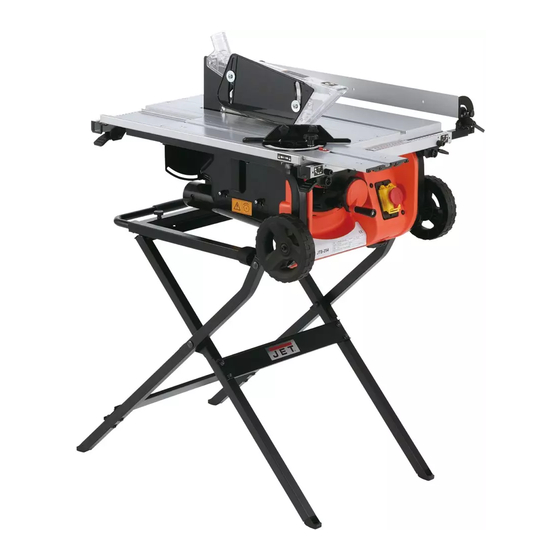
Jet JTS-254 Betriebsanleitung
Schweiz / Suisse
Walter Meier (TOOL) AG
Tämperlistrasse 5
CH-8117 Fällanden
Switzerland
tool-ag@waltermeier.com
www.jettools.com
France
TOOL France / PROMAC
57, rue du Bois Chaland, Z.I. du Bois Chaland
case postale 2935
FR-91029 Evry Cedex
info@promac.fr
www.promac.fr
2013.10
Deutschland / Oestreich
JET Tools GmbH
Im Taubental 4
DE-41468 Neuss
team@jetgmbh.de
www.jettools.com

Verwandte Anleitungen für Jet JTS-254


Inhaltszusammenfassung für Jet JTS-254
- Seite 1 2013.10 Schweiz / Suisse France Deutschland / Oestreich Walter Meier (TOOL) AG TOOL France / PROMAC JET Tools GmbH Tämperlistrasse 5 57, rue du Bois Chaland, Z.I. du Bois Chaland Im Taubental 4 CH-8117 Fällanden case postale 2935 DE-41468 Neuss...
- Seite 3 Dear Customer, Many thanks for the confidence you have shown in us with the purchase of your new JET-machine. This manual has been prepared for the owner and operators of a JET JTS-254 table saw to promote safety during installation, operation and maintenance procedures.
- Seite 7 scale. implementation in accordance with national Move the fence back and turn the framing 180 degree to law, electric tools that have reached the check the other side. end of their life must be collected If the two dimensions are not the same, loosen the four screws and align it.
- Seite 8 Gebrauchsanleitung Sehr geehrter Kunde, vielen Dank für das Vertrauen, welches Sie uns beim Kauf Ihrer neuen JET-Maschine entgegengebracht haben. Diese Anleitung ist für den Inhaber und die Bediener zum Zweck einer sicheren Inbetriebnahme, Bedienung und Wartung der Tischkreissäge JTS-254 erstellt worden. Beachten Sie bitte die Informationen dieser Gebrauchsanleitung und der beiliegenden Dokumente.
-
Seite 13: Consignes De Sécurité
Cher client, uvelle machine JET. Ce manuel a la scie circulaire JET JTS-254. Son but, mis à part le fonctionnement de la machine, est de maintenance. Avant de mettre he, lire les consignes de sécurité et de maintenance dans leur intégralité. Pour obtenir une longévité et llez lire attentivement ce mode ions. - Seite 14 pour manipuler l'outil. L'encombrement des zones et/ou plans de travail VEILLEZ À TOUJOURS GARDER L'ÉQUILIBRE. provoque des accidents. Veillez à ne pas trébucher ou à perdre l'équilibre. MAINTENEZ LES OUTILS EN BONNES CONDITIONS ENVIRONNEMENT À RISQUES. N'utilisez pas les D'UTILISATION. Veillez à conserver les arrêtes de appareils électriques dans des environnements coupe propres et bien acérées pour de meilleurs...
-
Seite 19: Entretien
ENTRETIEN l'audition. Par conséquent, le maniement de l'appareil doit ENTRETIEN GÉNÉRAL s'accompagner de protections auditives adaptées. AVERTISSEMENT : Débranchez toujours la fiche secteur. Contrôlez périodiquement les fixations, verrous, boulons, vis et Veuillez lire attentivement les instructions avant courroies pour s'assurer serrages de manipuler la machine. - Seite 21 E Assembly To install the extension table 1. Take the machine out of the carton. 2. Loose 4 clamps & mount the front/rear rails 3. Tighten 2 screws. D Zusammenbau - Montage des Ausziehtisches 1. Nehmen Sie das Gerät aus dem Karton. 2.
- Seite 22 D Bedienung: Einstellen des ausziehbaren Anschlags und der Schnittbreite zum Sägeblatt 1. Heben Sie das Sägeblatt indem Sie das Handrad zur Justierung von Höhe/Schrägstellung in die oberste Position bringen. 2. Lösen Sie die vorderen/hinteren Schienenklemmen. Bringen Sie den Anschlag in eine parallele Position zum Sägeblatt.
- Seite 23 E Operation: To use extension fence(A) 1. Pull the extension fence out of the table 2. Press the extension position buttons 3. Turn the fence and make the pin from position b point to position 4. Release the buttons and make the pin to lock position D Bedienung: Verwendung des ausziehbaren Anschlags (A) 1.
- Seite 24 E Operation: To use extension fence(B) 2. Loose the fence clamps 3. Turn down the fence in parallel position of the table 4. Pull the extension table to the demand position and lock the clamps D Bedienung: Verwendung des ausziehbaren Anschlags (B) 1.
- Seite 25 E Operation: To use the auxiliary fence extension fence indicator to 2. Set No. 162 Screws (x3) & No.163 Nuts (x3) into the holes of the extension fence 3. Slide aux. fence over nuts 4. Tighten No. 162 Screws (x3) D Bedienung: Verwendung des Hilfsanschlags 1.
- Seite 27 E Operation: Install blade guard assembly 1. Loose 4 screws and take off the table inserts 2. Raise the saw blade to top position and turn it to bevel position 10~15 degrees. 3. Loose riving knife plate 4. Set blade guard assembly into the riving knife dock & tighten riving knife plate 5.
- Seite 28 E Operation: To install/remove the saw blade 1. Reverse 2. Hold the arbor by wrench B 3. Release the nut by wrench A D Bedienung: Montage/Entfernung des Sägeblatts 1. Befolgen Sie die Anweisungen 1-4 in 2. Halten Sie die Blattwelle mit Schraubenschlüssel B. 3.
- Seite 29 E Operation: To install/remove the saw blade 4. Take off the shown parts as drawing 4 shown 5. Install new saw blade and parts as drawing 5 shown 6. Hold the arbor by wrench B & tighten the nut by wrench A D Bedienung: Montage/Entfernung des Sägeblatts 4.
- Seite 30 E Operation: Adjusting 90 and 45 degree positive stop 1. Loosen bevel handwheel and set the blade align the left side of angle gaueat 90 degree 2. Use 3mm wrench to loosen screw a few turns and move the blade until the blade is at 90 degree to the table, then tighten screw 3.
- Seite 31 D Bedienung: Justierung des Festanschlags für den 90 und 45 Grad Winkel 1. Lösen Sie das Handrad und richten Sie das Sägeblatt durch Kippen im linken Bereich in einem 90 Grad Winkel aus. 2. Verwenden Sie den 3 mm-Inbusschraubenschlüssel um die Schraube durch wenige Umdrehungen zu lösen und das Sägeblatt so zu bewegen, dass ein 90 Grad Winkel zwischen Sägeblatt und Tisch entsteht.
- Seite 32 F Fonctionnement : Réglage des butées fixes à 90 et 45 degrés 1. Desserrez le volant d'ajustement d'angle et réglez la lame de sorte qu'elle s'aligne sur l'angle de 90 degrés. 2. A l'aide de la clé de 3 mm, desserrez de quelques tours la vis et redressez la lame jusqu'à...
- Seite 33 E Operation: To use sliding table 1. Loosen Knob A & slide the miter gauge into the rail of sliding table (make sure miter gauge does not exceed the rail range), then tighten Knob A 2. Turn on lcok and set the sliding table to demanded position 3.
- Seite 34 E Operation: To use sliding table 5. Loosen Knob A and you may move the miter gauge from left rail to right rail D Bedienung: Verwendung des Schiebetischs 5. Lösen Sie Griff A, damit Sie das Gehrungsmaß von der linken zur rechten Schiene bewegen können.
- Seite 35 E Operation: To change carbon brush 1. Lower the saw blade to bottom position 2. Loosen carbon brush cap and replace carbon brush, then tighten the cap back D Bedienung: Auswechseln der Kohlebürste 1. Senken Sie das Sägeblatt auf die unterste Position. 2.
- Seite 36 E Miter Gauge D Gehrungsmaß E Power Cord F Guide de coupe angulaire D Netzkabel F Cordon d'alimentation E Sliding table D Schiebetisch F Plateau de glisse Operation: To move the machine(A) c. Wickeln Sie das Netzkabel im Gehäuse auf. a.
- Seite 37 E Operation: To move the machine (B) E Clamp e. Pull the handle to positive position and you may D Feststellen move the machine by pulling and wheeling F Verrouillage D Bedienung: Transport des Geräts (B) e. Ziehen Sie an dem Griff, bis er einrastet. Sie können das Gerät dann ziehend auf Rädern bewegen.
- Seite 38 START RESTART STOP...
- Seite 40 Ersatzteilliste / Liste de pièces détachés Schraube / Vis PM-254045 PM-254113 Gestänge / Lien Platte / Plate PM-254046 PM-254114 Schild / Etiquette Deckel / Couvercle PM-254047 PM-254115 Kopf / Tête Schraube / Vis PM-254048 PM-254116 Scheibe / Rondelle Rahmen / Carde PM-254049 PM-254117 Fuss / Pied...
- Seite 41 Ersatzteilliste / Liste de pièces détachés fuss / Pièd PM-254168 Schraube / Vis PM-254169 Griff / Poignée JTS-254-M PM-254170 Hebel / Poingnée PM-254171 Rohr / Tube PM-254172 Rahmen / Carde PM-254173 Griff / Poignée PM-254174 Blattschlüssel / Clé lame PM-254175 Blattschlüssel / Clé...
- Seite 42 Garantie Wir gewähren Ihnen auf den unten eingetragenen Artikeln Garantie auf die Dauer von 24 Monaten ab Laufdatum. Einzige Voraussetzung: die- eingesandten Maschine beigefügt sein. Par ce document nous nous engageons à réparer l‘article mentionné ci- dessous en garantie pendant une période de 24 mois à partir de la date plété...